EP0414503A2 - Appareil de décalage de feuilles - Google Patents
Appareil de décalage de feuilles Download PDFInfo
- Publication number
- EP0414503A2 EP0414503A2 EP90309170A EP90309170A EP0414503A2 EP 0414503 A2 EP0414503 A2 EP 0414503A2 EP 90309170 A EP90309170 A EP 90309170A EP 90309170 A EP90309170 A EP 90309170A EP 0414503 A2 EP0414503 A2 EP 0414503A2
- Authority
- EP
- European Patent Office
- Prior art keywords
- stacks
- sheets
- copy sheets
- tray
- offset
- Prior art date
- Legal status (The legal status is an assumption and is not a legal conclusion. Google has not performed a legal analysis and makes no representation as to the accuracy of the status listed.)
- Ceased
Links
Images
Classifications
-
- G—PHYSICS
- G03—PHOTOGRAPHY; CINEMATOGRAPHY; ANALOGOUS TECHNIQUES USING WAVES OTHER THAN OPTICAL WAVES; ELECTROGRAPHY; HOLOGRAPHY
- G03G—ELECTROGRAPHY; ELECTROPHOTOGRAPHY; MAGNETOGRAPHY
- G03G15/00—Apparatus for electrographic processes using a charge pattern
- G03G15/65—Apparatus which relate to the handling of copy material
- G03G15/6538—Devices for collating sheet copy material, e.g. sorters, control, copies in staples form
- G03G15/6547—Shifting sets of sheets in the discharge tray
-
- G—PHYSICS
- G03—PHOTOGRAPHY; CINEMATOGRAPHY; ANALOGOUS TECHNIQUES USING WAVES OTHER THAN OPTICAL WAVES; ELECTROGRAPHY; HOLOGRAPHY
- G03G—ELECTROGRAPHY; ELECTROPHOTOGRAPHY; MAGNETOGRAPHY
- G03G2215/00—Apparatus for electrophotographic processes
- G03G2215/00362—Apparatus for electrophotographic processes relating to the copy medium handling
- G03G2215/00789—Adding properties or qualities to the copy medium
- G03G2215/00822—Binder, e.g. glueing device
- G03G2215/00827—Stapler
-
- G—PHYSICS
- G03—PHOTOGRAPHY; CINEMATOGRAPHY; ANALOGOUS TECHNIQUES USING WAVES OTHER THAN OPTICAL WAVES; ELECTROGRAPHY; HOLOGRAPHY
- G03G—ELECTROGRAPHY; ELECTROPHOTOGRAPHY; MAGNETOGRAPHY
- G03G2215/00—Apparatus for electrophotographic processes
- G03G2215/00362—Apparatus for electrophotographic processes relating to the copy medium handling
- G03G2215/00886—Sorting or discharging
- G03G2215/0089—Shifting jobs
Definitions
- This invention relates generally to an electrophotographic reproduction machine, and more particularly concerns an apparatus for regulating offsetting stacks of copy sheets reproduced from at least one original document.
- a photoconductive member is charged to a substantially uniform potential so as to sensitize the surface thereof.
- the charged portion of the photoconductive member is exposed to a light image of an original document being reproduced. Exposure of the charged photoconductive member selectively dissipates the charge thereon in the irradiated areas.
- the latent image is developed by bringing a developer material into contact therewith.
- the developer material comprises toner particles adhering triboelectrically to carrier granules.
- the toner particles are attracted from the carrier granules to the latent image forming a toner powder image on the photoconductive member.
- the toner powder image is then transferred from the photoconductive member to a copy sheet.
- the toner particles are heated to permanently fix the powder image permanently to the copy sheet.
- the copy sheets are collected into unfinished stacks of copy sheets.
- the collected copy sheets may then be bound or stapled together into finished stacks of copy sheets. Finished or unfinished stacks of copy sheets are then stacked for presentation to the machine operator.
- US-A-4,603,971 discloses a printing machine which includes a finisher that can switch between modes of operation.
- the finisher may operate in either a stack mode, a staple set mode, or a bound set mode.
- the printing machine has a controller, and a switch for changing modes.
- the present invention aims at provided an apparatus for selectively offsetting stacks of sheets reproduced from at least one original document.
- the apparatus includes means for controlling offsetting of adjacent stacks of sheets from one another so that in one mode successive stacks of sheets are offset from one another, and in another mode there is no offsettingMeans are provided for receiving and supporting the sheets.
- Means responsive to the controlling means, move the receiving and supporting means at selected intervals to offset each stack from one another.
- the moving means is selectively de-energized in response to the controlling means to inhibit offsetting of the stacks of copy sheets from one another.
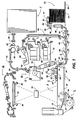
- FIG. 1 schematically depicts an electrophotographic printing machine incorporating the present invention therein.
- the apparatus of the present invention may be employed in a wide variety of devices and is not specifically limited in its application to the particular embodiment depicted herein.
- the electrophotographic printing machine employs a photoconductive belt 10.
- the photoconductive belt 10 is made from a photoconductive material coated on a ground layer, which, in turn, is coated on a anti-curl backing layer.
- the photoconductive material is made from a transport layer coated on a generator layer.
- the transport layer transports positive charges from the generator layer.
- the interface layer is coated on the ground layer.
- the transport layer contains small molecules of di-m-tolydiphenylbiphenyldiamine dispersed in a polycarbonate.
- the generation layer is made from trigonal selenium.
- the grounding layer is made from titanium-coated 'Mylar' (trademark). The ground layer is very thin and allows light to pass therethrough.
- Belt 10 moves in the direction of arrow 12 to advance successive portions of the photoconductive surface sequentially through the various processing stations disposed about the path of movement thereof.
- Belt 10 is entrained about stripping roller 14, tensioning roller 16, idler rollers 18, and drive roller 20.
- Stripping roller 14 and idler rollers 18 are mounted rotatably so as to rotate with belt 10.
- Tensioning roller 16 is resiliently urged against belt 10 to maintain belt 10 under the desired tension.
- Drive roller 20 is rotated by a motor coupled thereto by suitable means such as a belt drive. As roller 20 rotates, it advances belt 10 in the direction of arrow 12.
- corona-generating devices 22 and 24 charge photoconductive belt 10 to a relatively-high, substantially-uniform potential.
- Corona-generating device 22 places all of the required charge on photoconductive belt 10.
- Corona-generating device 24 acts as a leveling device, and fills in any areas missed by device 22.
- a document-handling unit 26 is positioned over platen 28 of the printing machine.
- Document handling unit 26 sequentially feeds original documents from a stack of documents placed by the operator face up in a normal forward collated order in the document stacking and holding tray.
- a document feeder located below the tray forwards the bottom document in the stack to a pair of take-away rollers.
- the bottom sheet is then fed by the rollers through a document guide to a feed roll pair and belt.
- the belt advances the document to platen 28.
- the original document is fed from platen 28 by the belt into a guide and feed roll pair.
- the document then advances into an inverter mechanism andback to the top of the stack of original documents through the feed roll pair.
- a position gate is provided to divert the document to the inverter or to the feed roll pair. Imaging of a document is achieved by lamps 30 which illuminate the document on platen 28. Light rays reflected from the document are transmitted through lens 32. Lens 32 focuses light images of the original document onto the charged portion of photoconductive belt 10 to dissipate the charge thereon selectively. This records an electrostatic latent image on the photoconductive belt which corresponds to the informational areas contained within the original document. In this way, a plurality of original documents may be sequentially exposed.
- document handling unit 26 may be pivoted away from platen 28 and an original document positioned manually thereon. One or more copies of the original document may be reproduced by the printing machine. The original document is exposed and a latent image recorded on the photoconductive belt. Thereafter, belt 10 advances the electrostatic latent image recorded thereon to development station C.
- Development station C has three magnetic brush developer rolls 34, 36 and 38.
- a paddle wheel picks up developer material and delivers it to the developer rolls. When developer material reaches rolls 34 and 36, it is magnetically split between the rolls, with half the developer material being delivered to each roll.
- Photoconductive belt 10 is partially wrapped about rolls 34 and 36 to form extended development zones.
- Developer roll 38 is a cleanup roll.
- a magnetic roll, positioned after developer roll 38, in the direction of arrow 12, is a carrier granule removal device adapted to remove any carrier granules adhering to belt 10.
- rolls 34 and 36 advance developer material into contact with the electrostatic latent image.
- the latent image attracts toner particles from the carrier granules of the developer material to form a toner powder image on the photoconductive surface of belt 10.
- Belt 10 then advances the toner powder image to transfer station D.
- a copy sheet is moved into contact with the toner powder image.
- photoconductive belt 10 is exposed to a pre-transfer light from a lamp (not shown) to reduce the attraction between photoconductive belt 10 and the toner powder image.
- a corona-generating device 40 charges the copy sheet to the proper magnitude and polarity so that the copy sheet is tacked to photoconductive belt 10 and the toner powder image attracted from the photoconductive belt to the copy sheet.
- corona generator 42 charges the copy sheet to the opposite polarity to detack the copy sheet from belt 10.
- Conveyor 44 advances the copy sheet to fusing station E.
- Fusing station £ includes a fuser assembly which permanently affixes the transferred toner powder image to the copy sheet.
- fuser assembly 46 includes a heated fuser roller 48 and a pressure roller 50, with the powder image on the copy sheet contacting fuser roller 48.
- the pressure roller is cammed against the fuser roller to provide the necessary pressure to fix the toner powder image to the copy sheet.
- the fuser roll is internally heated by a quartz lamp.
- Release agent stored in a reservoir, is pumped to a metering roll. A trim bladetrims off the excess release agent. The release agent transfers to a donor roll and then to the fuser roll.
- Decurler 52 bends the copy sheet in one direction to put a known curl in the copy sheet and then bends it in the opposite direction to remove that curl.
- Duplex solenoid gate 58 guides the sheet to the finishing station F or to duplex tray 60.
- finishing station F copy sheets are stacked in compiler trays to form stacks of copy sheets.
- the stacks of copy sheets may remain unfinished or may be finished by being attached to one another by either a binding device or a stapling device. In either case, a plurality of finished or unfinished stacks of copy sheets are formed in finishing station F.
- the stacks of copy sheets are delivered to a stacker. In the stacker, each stack of copy sheets may be offset from the adjacent stacks, or offsetting may be inhibited and the stacks of copy sheets aligned with one another.
- the operator selects the number of uncollated copy sheets in a stack, and if the stacks of uncollated copy sheets are to be offset from one another. Alternatively, the operator may inhibit the offsetting of stacks. Further details of controlling offsetting stacks of copy sheets will be described hereinafter with reference to Figure 4. The general operation of finishing station F will be described hereinafter with reference to Figure 2.
- duplex solenoid gate 58 diverts the sheet into duplex tray 60, it provides an intermediate or buffer storage for those sheets that have been printed on one side and on which an image will be subsequently printed on the second, opposed side thereof, i.e. the sheets are to be duplexed.
- the sheets are stacked in duplex tray 60 face down on top of one another in the order in which they are copied.
- the simplex sheets in tray 60 are fed seriatim by bottom feeder 62 from tray 60 back to transfer station D via conveyor 64 and rollers 66 for transfer of the toner powder image to the second sides of the copy sheets.
- the proper or clean side of the copy sheet is positioned in contact with belt 10 at transfer station D so that the toner powder image is transferred thereto.
- the duplex sheet is then fed through the same path as the simplex sheet to be advanced to finishing station F.
- Copy sheets are fed to transfer station D from the secondary tray 68.
- the secondary tray 68 includes an elevator driven by a bidirectional AC motor. Its controller has the ability to drive the tray up or down. When the tray is in its 'down' position, stacks of copy sheets are loaded thereon or unloaded therefrom. In its 'up' position, successive copy sheets may be fed therefrom by sheet feeder 70.
- Sheet feeder 70 is a friction retard feeder utilizing a feed belt and take-away rolls to advance successive copy sheets to transport 64 which advances the sheets to rolls 66 and then to transfer station D.
- Copy sheets may also be fed to transfer station ID from the auxiliary tray 72.
- the auxiliary tray 72 includes an elevator driven by a bidirectional AC motor. Its controller has the ability to drive the tray up or down. When the tray is in its 'down' position, stacks of copy sheets are loaded thereon or unloaded therefrom. In its 'up' position, successive copy sheets may be fed therefrom by sheet feeder 74.
- Sheet feeder 74 is a friction retard feeder utilizing a feed belt and take-away rolls to advance successive copy sheets to transport 64 which advances the sheets to rolls 66 and then to transfer station D.
- a high capacity feeder 76 is the primary source of copy sheets.
- High capacity feeder 76 includes a tray 78 supported on an elevator 80.
- the elevator is driven by a bidirectional AC motor to move the tray up or down. In the up position, the copy sheets are advanced from the tray to transfer station D.
- a fluffer and air knife 83 direct air onto the stack of copy sheets on tray 78 to separate the uppermost sheet from the stack. Suction pulls the uppermost sheet against feed belt 81.
- Feed belt 81 feeds successive uppermost sheets from the stack to a take-away drive roll 82 and idler rolls 84.
- the drive roll and idler rolls guide the sheet onto transport 86.
- Transport 86 advances the sheet to rolls 66 which, in turn, move the sheet to transfer station D.
- cleaning station G includes an electrically biased cleaner brush 88 and two de-toning rolls 90 and 92, i.e. waste and reclaim de-toning rolls.
- the reclaim roll is electrically biased negatively relative to the cleaner roll, so as to remove toner particles therefrom.
- the waste roll is electrically biased positively relative to the reclaim roll so as to remove paper debris and wrong-sign toner particles.
- the toner particles on the reclaim roll are scraped off and deposited in a reclaim auger (not shown), by which they are transported out of the rear of cleaning station G.
- the various machine functions are regulated by a controller 96 ( Figure 4).
- the controller is preferably a programmable microprocessor which controls all of the machine functions hereinbefore described.
- the controller provides a comparison count of the copy sheets, the number of documents being recirculated, the number of copy sheets selected by the operator, time delays, jam corrections. etc.
- the control of all of the exemplary systems heretofore described may be accomplished by conventional control switch inputs from the printing machine console
- Conventional sheet path sensors or switches may be utilized to keep track of the position of the documents and the copy sheets.
- the controller regulates the various positions of the gates, depending upon the mode of operation selected. Further details ofthe operation of controller 96 for regulating offsetting stacks of copy sheets will be described hereinafter with reference to Figure 4.
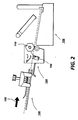
- Finishing station F receives fused copies from rolls 98 ( Figure 1) and advances them in the direction of arrow 102 to the compiler tray 100.
- Compiler tray 100 has two positions, an upper position and a lower position.
- the compiler tray is moved to the upper position in order to compile and be in a position to staple the stacks of collated or uncollated copies.
- the compiler tray is moved to the lower position. The stapled stack of copy sheets is then ejected and the compiler tray is raised to the upper position ready to compile the next stack of copy sheets for stapling.
- the lower position is used to compile stacks of collated or uncollated copy sheets that are not being stapled.
- the compiler tray is ready to compile the next stack of copy sheets.
- the control logic senses that a stack of collated or uncollated copy sheets is complete.
- the stack of copy sheets is ready to leave compiler tray 100.
- the stack of copy sheets is ejected into the output transport assembly 104 which drives the stack of copy sheets out of compiler tray 100 into a stacker.
- Output switch 108 senses each stack of copy sheets as it leaves compiler tray 100. Output switch 108 informs the controller if a jam occurs. If a jam does occur, the controller then generates a fault signal.
- Stacks of copy sheets can range in thickness from about two sheets to one hundred sheets. Because of the wide range of sheet sizes and the varying thicknesses of the stacks of copy sheets, hexagonai-sectioned foam rolls 110 are used to provide a uniform nip force to drive the stacks of copy sheets to stacker 106.
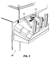
- Figure 3 shows the stacker in greater detail.
- stacker 106 receives the stacks of copy sheets from compiler tray 100.
- Stacker 106 adjusts to the size and quantity of the selected job by moving in the vertical direction and the widthwise direction. Stacker width movement occurs at the start of any job that has the finisher selected.
- the controller senses the size of the copy sheet that is in the selected copy sheet tray of the printing machine.
- a motor moves the stacker tray to the appropriate width. Vertical movement of the stacker ensures that each stack of copy sheets being delivered to the stacker does so at the same angle.
- a motor will continue to lower the stacker tray so that the top of the stack stays a specific distance from the stack exit point.
- the controller senses when the stacks of copy sheets have been removed and will then raise the stacker tray to its highest position.
- a plurality of stacks of collated or uncollated copy sheets may be stacked on the tray of stacker 106.
- the stacker may offset adjacent stacks of copy sheets from one another by moving in the direction of arrows 112 between successive stacks of copy sheets.
- An operator may select whether or not adjacent stacks of copy sheets are to be offset from one another.
- the selection of offset control is made in the diagnostics access mode of the printing machine. In this way, successive stacks of uncollated copy sheets may be offset from one another, while successive stacks of collated copy sheets are not offset from one another. Further details of offsetting stacks of copy sheets from one another are discussed below with reference to Figure 4.
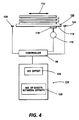
- FIG. 4 shows the apparatus for controlling offsetting stacks of collated and uncollated copy sheets from one another.
- Stacker 106 includes a tray 114. Tray 114 is moved to its two offset positions by an AC motor 116 coupled to a surface cam 118. Cam 118 has a groove that a pin attached to the lower portion of tray 114 follows when motor 116 rotates cam 118. This groove translates the motor rotational movement into forward or reverse movement, depending upon the direction that motor 116 rotates. Guide pins in slots on the lower portion of tray 114 allow forward or reverse movement of the tray while maintaining the height and width of the tray. Switches 120 and 122, when actuated, signal to controller 96 that the tray is in the forward or reverse position. The controller, in turn, signals to stop forward or reverse movement. In this way, while stacks of copy sheets are being loaded onto the tray, the tray alternately offsets adjacent stacks of copy sheets about 35 millimeters.
- a display 124 has a plurality of operator-actuatable regions 126 and 128.
- Display 124 may be a keyboard having keys 126 and 128 thereon.
- display 124 may be a touch screen of which discrete regions display keys 126 and 128 which are actuatable by the operator touching the respective region of the screen.
- display 124 transmits a signal to controller 96.
- controller 96 may actuate or inhibit motor 116 from rotating cam 118 so as to move tray 114 after the number of copy sheets corresponding to the selected stack size have been stacked thereon.
- Switches 120 and 122 transmit a signal to controller 96 indicating that the tray 114 has moved as required so as to offset successive stacks of copy sheets from one another at the correct interval. The operator may also determine the number of copy sheets in each stack.
- Controller 96 includes a non-volatile memory which controls motor 116. Actuation of key 128 sets the bit position in the non-volatile memory to 'True' for stacks of uncollated copy sheets.
- the operator may also select the number of sheets to be included in the stack by actuating the appropriate keys on the number pad on the console of the printing machine until the desired number of copy sheets is displayed on the printing machine display.
- Each copy sheet of each stack may be a copy of the same original document. In this mode, successive stacks of uncollated copy sheets are offset from one another. The stacks of copy sheets may be stapled or unstapled.
- controller 96 energizes motor 116 at successive intervals after successive stacks each having the selected number of copy sheets therein have been stacked on tray 114.
- switches 120 and 122 transmit a signal to controller 96 verifying that tray 114 has offset the stacks of uncollated copy sheets at the selected interval.
- the bit position for 'offset inhibit' in the non-volatile memory of controller 96 is set to 'True'. This de-energizes motor 116, and the stacks of collated copy sheets stacked on tray 114 are aligned with one another. Thus, when key 126 is selected by the operator, there is no offset and the stacks of collated sheets on tray 114 are straight, i.e. in-line. In the default mode, i. e. when keys 126 and 128 are not actuated by the operator, the bit position for the non-volatile memory of controller 96 is 'Not True'. Controller 96 de-energizes motor 116 when stacks of uncollated copy sheets are being advanced to tray 114.
- the apparatus of the present invention permits the operator to have the stacker of the printing machine offset stacks of uncollated copy sheet, while stacks of coated copy sheets are not offset from one another.
- the number of copy sheets in the stack of uncollated copy sheets may also be selected by the operator. In the default mode, each stack of coilated copy sheets is offset from one another while each stack of uncollated copy sheets is not offset, i.e. the stacks of uncollated copy sheets are aligned with one another.
Landscapes
- Physics & Mathematics (AREA)
- General Physics & Mathematics (AREA)
- Pile Receivers (AREA)
- Paper Feeding For Electrophotography (AREA)
- Forming Counted Batches (AREA)
- Control Or Security For Electrophotography (AREA)
- Folding Of Thin Sheet-Like Materials, Special Discharging Devices, And Others (AREA)
Applications Claiming Priority (2)
| Application Number | Priority Date | Filing Date | Title |
|---|---|---|---|
| US07/398,858 US5007625A (en) | 1989-08-24 | 1989-08-24 | Selectable sheet offsetting |
| US398858 | 1989-08-24 |
Publications (2)
| Publication Number | Publication Date |
|---|---|
| EP0414503A2 true EP0414503A2 (fr) | 1991-02-27 |
| EP0414503A3 EP0414503A3 (en) | 1991-07-03 |
Family
ID=23577072
Family Applications (1)
| Application Number | Title | Priority Date | Filing Date |
|---|---|---|---|
| EP19900309170 Ceased EP0414503A3 (en) | 1989-08-24 | 1990-08-21 | Sheet offsetting apparatus |
Country Status (4)
| Country | Link |
|---|---|
| US (1) | US5007625A (fr) |
| EP (1) | EP0414503A3 (fr) |
| JP (1) | JP2931651B2 (fr) |
| CA (1) | CA2021746C (fr) |
Cited By (2)
| Publication number | Priority date | Publication date | Assignee | Title |
|---|---|---|---|---|
| EP2295358A3 (fr) * | 2009-09-10 | 2012-08-22 | Canon Kabushiki Kaisha | Appareil de formation d'images |
| WO2014175791A1 (fr) | 2013-04-22 | 2014-10-30 | Sca Hygiene Products Ab | Empilement et procédé de distribution |
Families Citing this family (24)
| Publication number | Priority date | Publication date | Assignee | Title |
|---|---|---|---|---|
| US5173785A (en) * | 1988-12-21 | 1992-12-22 | Minolta Camera Co., Ltd. | Image forming apparatus |
| US5080340A (en) * | 1991-01-02 | 1992-01-14 | Eastman Kodak Company | Modular finisher for a reproduction apparatus |
| EP0676302B1 (fr) * | 1991-01-02 | 1998-11-25 | Eastman Kodak Company | Brocheuse de selle pour appareil de finition modulaire |
| US5447297A (en) * | 1992-06-26 | 1995-09-05 | Canon Kabushiki Kaisha | Sheet post-processing apparatus |
| US5443248A (en) * | 1992-06-29 | 1995-08-22 | Canon Kabushiki Kaisha | Sheet post-processing apparatus |
| US5501442A (en) * | 1993-11-08 | 1996-03-26 | Xerox Corporation | Dual mode tamper/offsetter |
| US5513839A (en) * | 1994-09-23 | 1996-05-07 | Xerox Corporation | Dual mode set stacking tamper and sheet feeder offset system |
| US5618035A (en) * | 1994-11-25 | 1997-04-08 | Gradco (Japan) Ltd. | Offset stacker |
| JP3311969B2 (ja) * | 1997-08-29 | 2002-08-05 | 富士通株式会社 | 印刷装置における排紙位置制御方法及び装置 |
| US6390465B1 (en) * | 1997-09-30 | 2002-05-21 | Canon Kabushiki Kaisha | Sheet process apparatus performing binding process on sheets featuring a controller for shifting sheet discharge |
| US6056288A (en) * | 1998-12-22 | 2000-05-02 | Xerox Corporation | Self adjusting controlled acceleration sheet stacking offsetting system |
| US6227531B1 (en) | 1999-05-25 | 2001-05-08 | Hewlett-Packard Company | Job separation process, system and method for distributing print jobs |
| JP2001039614A (ja) * | 1999-07-30 | 2001-02-13 | Canon Inc | 画像形成装置 |
| US6695302B1 (en) | 1999-10-29 | 2004-02-24 | Energy Saving Products And Sales Corporation | Method and apparatus for separating a stream of spaced documents into discrete groups |
| US6384901B1 (en) | 2000-01-21 | 2002-05-07 | Hewlett-Packard Company | Sheet media skew adjustment in a printer output |
| JP3884943B2 (ja) * | 2000-12-26 | 2007-02-21 | キヤノン株式会社 | 情報処理装置、印刷データ生成方法、印刷制御プログラム及びコンピュータ読み取り可能な記録媒体 |
| US7448615B2 (en) * | 2002-10-23 | 2008-11-11 | Canon Kabushiki Kaisha | Sheet processing apparatus featuring relatively-displaced stapled sheet bundles and related method |
| JP4280259B2 (ja) * | 2005-11-09 | 2009-06-17 | シャープ株式会社 | 画像形成装置 |
| US7666129B2 (en) * | 2006-04-28 | 2010-02-23 | Pitney Bowes Inc. | Paper folder utilizing sheet inversion to develop auxiliary fold types |
| US8064083B2 (en) * | 2007-04-30 | 2011-11-22 | Xerox Corporation | Pad printing user interface dialog for copy or print |
| US20110187037A1 (en) | 2010-02-01 | 2011-08-04 | Xerox Corporation | Sawtooth jog for multi-copy/multi-set output |
| US8100393B2 (en) | 2010-02-01 | 2012-01-24 | Xerox Corporation | Sawtooth jog for multi-copy/multi-set output |
| US8517368B1 (en) | 2012-02-10 | 2013-08-27 | Xerox Corporation | Stapler eject with alternating offset and position controlled grip |
| TWI600602B (zh) * | 2016-05-20 | 2017-10-01 | 虹光精密工業股份有限公司 | 具有分類模組的影像形成設備 |
Family Cites Families (11)
| Publication number | Priority date | Publication date | Assignee | Title |
|---|---|---|---|---|
| US4134672A (en) * | 1976-03-30 | 1979-01-16 | Eastman Kodak Company | Copier finisher for an electrographic reproducing device |
| DE2732673A1 (de) * | 1977-03-25 | 1978-09-28 | Eastman Kodak Co | Kopiereinrichtung |
| JPS5438072A (en) * | 1977-08-31 | 1979-03-22 | Ricoh Co Ltd | Method of sorting discharged sheets |
| US4208122A (en) * | 1977-11-28 | 1980-06-17 | Ricoh Company, Ltd. | Reproduction apparatus comprising sorting device |
| JPS5912045A (ja) * | 1982-07-09 | 1984-01-21 | Canon Inc | シ−ト収積装置 |
| US4568172A (en) * | 1983-10-13 | 1986-02-04 | Xerox Corporation | Small document set recirculative copying |
| JPS60238856A (ja) * | 1984-05-11 | 1985-11-27 | Toshiba Corp | 集積装置 |
| US4603971A (en) * | 1984-09-17 | 1986-08-05 | Xerox Corporation | Finisher mode switching |
| JPS61114961A (ja) * | 1984-11-10 | 1986-06-02 | Nippon Seimitsu Kogyo Kk | 排出用紙区分け装置 |
| US4772917A (en) * | 1985-03-05 | 1988-09-20 | Ricoh Company, Ltd. | Copier with double-face copying and/or composite copying capability and intermediate sheet feeder therefor |
| JPS61295969A (ja) * | 1985-06-25 | 1986-12-26 | Nippon Seimitsu Kogyo Kk | 用紙積載装置 |
-
1989
- 1989-08-24 US US07/398,858 patent/US5007625A/en not_active Expired - Lifetime
-
1990
- 1990-07-23 CA CA002021746A patent/CA2021746C/fr not_active Expired - Fee Related
- 1990-08-21 EP EP19900309170 patent/EP0414503A3/en not_active Ceased
- 1990-08-21 JP JP2218298A patent/JP2931651B2/ja not_active Expired - Fee Related
Cited By (4)
| Publication number | Priority date | Publication date | Assignee | Title |
|---|---|---|---|---|
| EP2295358A3 (fr) * | 2009-09-10 | 2012-08-22 | Canon Kabushiki Kaisha | Appareil de formation d'images |
| WO2014175791A1 (fr) | 2013-04-22 | 2014-10-30 | Sca Hygiene Products Ab | Empilement et procédé de distribution |
| EP2988639A4 (fr) * | 2013-04-22 | 2016-12-21 | Sca Hygiene Prod Ab | Empilement et procédé de distribution |
| US10144576B2 (en) | 2013-04-22 | 2018-12-04 | Essity Hygiene And Health Aktiebolag | Stack and method of dispensing |
Also Published As
| Publication number | Publication date |
|---|---|
| JP2931651B2 (ja) | 1999-08-09 |
| US5007625A (en) | 1991-04-16 |
| CA2021746C (fr) | 1997-08-19 |
| JPH03106754A (ja) | 1991-05-07 |
| CA2021746A1 (fr) | 1991-02-25 |
| EP0414503A3 (en) | 1991-07-03 |
Similar Documents
| Publication | Publication Date | Title |
|---|---|---|
| US5007625A (en) | Selectable sheet offsetting | |
| US5379668A (en) | Trimmer blower and high capacity waste bin | |
| US5017972A (en) | Elevator tray position control apparatus | |
| US5335903A (en) | High capacity dual tray variable sheet size sheet feeder | |
| US4801135A (en) | Sheet handling apparatus | |
| EP0099250B2 (fr) | Empileuse pour feuilles | |
| US5364087A (en) | Tilting tray for feeding and stacking specialized forms | |
| US4989853A (en) | Apparatus for offsetting sheets | |
| US4874958A (en) | Sheet edge detector | |
| EP0361850B1 (fr) | Dispositif d'alimentation et de mise à niveau des feuilles | |
| EP0428372B1 (fr) | Agrafeuse | |
| US5018717A (en) | Sheet stacking apparatus | |
| US4919410A (en) | Apparatus for determining copy sheet set thickness | |
| EP0365284B1 (fr) | Dispositif pour faire sortir des piles de papier | |
| US5228679A (en) | Sheet damping mechanism | |
| US5941518A (en) | Sheet feeder with variable length, variable speed sheetpath | |
| US5300993A (en) | Transfer assist apparatus | |
| US4797048A (en) | Binding apparatus | |
| US4886259A (en) | Sorter-finisher system | |
| US5146286A (en) | Compact copy sheet input/output apparatus for an electrophotographic printing machine | |
| US4831416A (en) | Sheet set advancing apparatus | |
| US4891680A (en) | Transfer apparatus | |
| US4751547A (en) | Sheet guide | |
| US5761596A (en) | Paper path inlet baffle | |
| US4913414A (en) | Damped sheet registration drive |
Legal Events
| Date | Code | Title | Description |
|---|---|---|---|
| PUAI | Public reference made under article 153(3) epc to a published international application that has entered the european phase |
Free format text: ORIGINAL CODE: 0009012 |
|
| AK | Designated contracting states |
Kind code of ref document: A2 Designated state(s): DE FR GB |
|
| PUAL | Search report despatched |
Free format text: ORIGINAL CODE: 0009013 |
|
| AK | Designated contracting states |
Kind code of ref document: A3 Designated state(s): DE FR GB |
|
| 17P | Request for examination filed |
Effective date: 19911223 |
|
| 17Q | First examination report despatched |
Effective date: 19930906 |
|
| STAA | Information on the status of an ep patent application or granted ep patent |
Free format text: STATUS: THE APPLICATION HAS BEEN REFUSED |
|
| 18R | Application refused |
Effective date: 19941205 |