EP0414595B1 - Verfahren zum Schweissen durch Lichtbogenablenkung - Google Patents
Verfahren zum Schweissen durch Lichtbogenablenkung Download PDFInfo
- Publication number
- EP0414595B1 EP0414595B1 EP90402305A EP90402305A EP0414595B1 EP 0414595 B1 EP0414595 B1 EP 0414595B1 EP 90402305 A EP90402305 A EP 90402305A EP 90402305 A EP90402305 A EP 90402305A EP 0414595 B1 EP0414595 B1 EP 0414595B1
- Authority
- EP
- European Patent Office
- Prior art keywords
- tube
- arc
- welding
- row
- path
- Prior art date
- Legal status (The legal status is an assumption and is not a legal conclusion. Google has not performed a legal analysis and makes no representation as to the accuracy of the status listed.)
- Expired - Lifetime
Links
- 238000003466 welding Methods 0.000 title claims description 101
- 238000000034 method Methods 0.000 title claims description 49
- 238000006073 displacement reaction Methods 0.000 claims description 14
- 238000010891 electric arc Methods 0.000 claims description 14
- 230000004907 flux Effects 0.000 claims description 8
- 238000010408 sweeping Methods 0.000 description 6
- RYGMFSIKBFXOCR-UHFFFAOYSA-N Copper Chemical compound [Cu] RYGMFSIKBFXOCR-UHFFFAOYSA-N 0.000 description 5
- HCHKCACWOHOZIP-UHFFFAOYSA-N Zinc Chemical compound [Zn] HCHKCACWOHOZIP-UHFFFAOYSA-N 0.000 description 5
- 229910052802 copper Inorganic materials 0.000 description 5
- 239000010949 copper Substances 0.000 description 5
- 230000010355 oscillation Effects 0.000 description 5
- 239000011701 zinc Substances 0.000 description 5
- 229910052725 zinc Inorganic materials 0.000 description 5
- 229910001369 Brass Inorganic materials 0.000 description 4
- 239000010951 brass Substances 0.000 description 4
- 230000008569 process Effects 0.000 description 4
- ATJFFYVFTNAWJD-UHFFFAOYSA-N Tin Chemical compound [Sn] ATJFFYVFTNAWJD-UHFFFAOYSA-N 0.000 description 3
- 230000000295 complement effect Effects 0.000 description 3
- 238000012986 modification Methods 0.000 description 3
- 230000004048 modification Effects 0.000 description 3
- 229910052782 aluminium Inorganic materials 0.000 description 2
- XAGFODPZIPBFFR-UHFFFAOYSA-N aluminium Chemical compound [Al] XAGFODPZIPBFFR-UHFFFAOYSA-N 0.000 description 2
- 230000005540 biological transmission Effects 0.000 description 2
- 238000010586 diagram Methods 0.000 description 2
- 239000007789 gas Substances 0.000 description 2
- 239000011261 inert gas Substances 0.000 description 2
- 230000003534 oscillatory effect Effects 0.000 description 2
- WFKWXMTUELFFGS-UHFFFAOYSA-N tungsten Chemical compound [W] WFKWXMTUELFFGS-UHFFFAOYSA-N 0.000 description 2
- 229910052721 tungsten Inorganic materials 0.000 description 2
- 239000010937 tungsten Substances 0.000 description 2
- 208000031968 Cadaver Diseases 0.000 description 1
- 241000287107 Passer Species 0.000 description 1
- 230000009471 action Effects 0.000 description 1
- 230000006978 adaptation Effects 0.000 description 1
- HSFWRNGVRCDJHI-UHFFFAOYSA-N alpha-acetylene Natural products C#C HSFWRNGVRCDJHI-UHFFFAOYSA-N 0.000 description 1
- 239000011324 bead Substances 0.000 description 1
- 125000002534 ethynyl group Chemical group [H]C#C* 0.000 description 1
- 230000001788 irregular Effects 0.000 description 1
- 238000005304 joining Methods 0.000 description 1
- 238000004519 manufacturing process Methods 0.000 description 1
- 239000000463 material Substances 0.000 description 1
- 229910052751 metal Inorganic materials 0.000 description 1
- 239000002184 metal Substances 0.000 description 1
- 150000002739 metals Chemical class 0.000 description 1
- 230000002093 peripheral effect Effects 0.000 description 1
- 230000002787 reinforcement Effects 0.000 description 1
- 230000000284 resting effect Effects 0.000 description 1
- 229910000679 solder Inorganic materials 0.000 description 1
- 238000005476 soldering Methods 0.000 description 1
- 238000010998 test method Methods 0.000 description 1
Images


Classifications
-
- B—PERFORMING OPERATIONS; TRANSPORTING
- B23—MACHINE TOOLS; METAL-WORKING NOT OTHERWISE PROVIDED FOR
- B23K—SOLDERING OR UNSOLDERING; WELDING; CLADDING OR PLATING BY SOLDERING OR WELDING; CUTTING BY APPLYING HEAT LOCALLY, e.g. FLAME CUTTING; WORKING BY LASER BEAM
- B23K9/00—Arc welding or cutting
- B23K9/08—Arrangements or circuits for magnetic control of the arc
-
- B—PERFORMING OPERATIONS; TRANSPORTING
- B23—MACHINE TOOLS; METAL-WORKING NOT OTHERWISE PROVIDED FOR
- B23K—SOLDERING OR UNSOLDERING; WELDING; CLADDING OR PLATING BY SOLDERING OR WELDING; CUTTING BY APPLYING HEAT LOCALLY, e.g. FLAME CUTTING; WORKING BY LASER BEAM
- B23K9/00—Arc welding or cutting
- B23K9/02—Seam welding; Backing means; Inserts
- B23K9/028—Seam welding; Backing means; Inserts for curved planar seams
- B23K9/0288—Seam welding; Backing means; Inserts for curved planar seams for welding of tubes to tube plates
-
- F—MECHANICAL ENGINEERING; LIGHTING; HEATING; WEAPONS; BLASTING
- F28—HEAT EXCHANGE IN GENERAL
- F28F—DETAILS OF HEAT-EXCHANGE AND HEAT-TRANSFER APPARATUS, OF GENERAL APPLICATION
- F28F9/00—Casings; Header boxes; Auxiliary supports for elements; Auxiliary members within casings
- F28F9/02—Header boxes; End plates
- F28F9/04—Arrangements for sealing elements into header boxes or end plates
- F28F9/16—Arrangements for sealing elements into header boxes or end plates by permanent joints, e.g. by rolling
- F28F9/18—Arrangements for sealing elements into header boxes or end plates by permanent joints, e.g. by rolling by welding
Definitions
- the present invention relates to the welding of heat exchange tubes to the collector of equipment such as an automobile radiator body. More specifically, it proposes a method of welding by sweeping a row of tube ends projecting through orifices made in the collector and, in this way, welding the ends of the tube to the collector around the entire periphery. of the tube.
- the welding machine follows the outline, turning around the complete perimeter, of a generally oval shaped assembly joint formed by the generally oval end of the tube projecting through an orifice made in the collector.
- the ends of the tubes generally form a set of rows of oval welds and the welding device, in the prior art, subjected to various combinations controlled manually or automatically, positions the end of the welding head at a point. starting point fixed on the oval, starts the arc, then follows the line all along the circumference of the oval tube to perform the welding.
- the welding head is then moved to a second oval and the welding cycle is repeated. It is conventional to carry out this welding process in an environment of Tungsten inert gas (TIG).
- Tungsten inert gas Tungsten inert gas
- Such a line welding technique can pose a problem in that it can produce porous welds which are therefore weak and which favor leaks.
- Brass made up of around 70% copper and 30% zinc, is commonly used to make both manifolds and tubes. Since the welding temperatures that occur in the spot welding process can reach 5,580 ° C (10,000 ° F), a relatively large amount of heat is applied to the weld. Zinc tends to boil and leave the copper relatively porous, resulting in a weak weld. A subsequent supply of soldering tin on the welds to reinforce the assembly is therefore often necessary. Even after this, when the radiator body is subjected to the thermal, mechanical and pressure stresses inherent in the operation of vehicle engines, leaks and failures occur at an undesirable frequency.
- the sweep welding method uses alternating current rather than direct current as the welding current.
- the sweep welding machine is equipped with a welding head, means for moving said head along a row of tube ends, and a generator of magnetic flux lines causing the oscillation of the welding arc back and forth in a direction perpendicular to the path followed by the welding head.
- One of the aims of the present invention is to provide a method of sweep welding to weld a series of rows of tube ends to a manifold which avoids the tedious need to trace each assembly to be welded one after the other. other.
- One of the complementary aims of the present invention is to provide a method of welding by sweep to weld a series of rows of tube ends to a collector with which the welding head can be moved back and forth in a linear sweep mode on the tube ends rather than in a weld tracing mode one after the other.
- One of the complementary aims of the present invention is to provide a method of sweep welding to weld in series rows of tube ends to a collector with which a more complete and more continuous weld is obtained.
- the number 10 identifies a small section of a heat exchanger such as a vehicle radiator body with a tube plate 12 such as that of a radiator manifold with a single end of tube 14 projecting therefrom.
- a line 16 marks out a generally oval shape which corresponds to the line where the assembly must be welded by an electric arc 18 represented by the circle 20, as for example by an electric arc produced by a suitable electric current and voltage supplied by a torch not shown here (see Figure 3 below).
- the arc 18 will produce a welded surface along the part of the assembly line 16 wherever the arc touches this assembly, generally inside or in a region close to said circle 20.
- the arc 18 moves - not around the joining joint 16 - but rather through the end of the tube 14 in a first direction chosen generally linear over the axis of movement indicated generally by the arrow 26 at a predetermined generally constant speed, while, at the same time, the arc 18 is swept back and forth in a transverse direction as indicated by the arrow at double direction 28 with an alternating or oscillating movement of an amplitude indicated by the dotted lines 30 and 32 sufficient to touch the assembly joint by its large diameter 34 and around the entire periphery of the wall of the oval tube while the arc 18 moves along the small diameter 36 from the end of the tube 14.
- a weld whose surface which, instead of corresponding only to the points where the circle 20 of relatively small diameter touches the joint of assembly 16, is widened to include any portion of the joint comprised between lines 30 and 32.
- the voltage and the current can be varied in conjunction while the speed of movement corresponding to the small diameter is controlled on the other hand 36 and the frequency of oscillations back and forth in the direction of arrow 28 in order to obtain the desired weld surface taking into account the types of collector and tubes used.
- Other variables which can be adjusted are the momentary stopping times of right and left when the arc stops temporarily at the right and left extreme points of its oscillation in the direction of arrow 28.
- Figure 1 illustrates the preferred method in which the arc 18 moves in a straight line along the small diameter 36 of the end of the tube 14 by the central axis 38 around which the tube is formed, while, simultaneously, the arc 18 oscillates in directions 28 perpendicular to direction 26.
- the method of sweep welding can be carried out with variants which are within the scope of the present invention.
- the arc 18 can move in the first direction other than the straight line while it undergoes a generally transverse alternating movement which is not necessarily perpendicular to said first direction but have only one of its components normal to said first direction.
- the arc 18 can also follow an axis of displacement which passes through said tube through a point other than its center 38.
- the axis of displacement does not even need to pass through the end of the tube 14 if the transverse movement has a sufficient amplitude to touch the assembly joint 16. Also, if the amplitude of the reciprocating movement does not allow the arc 18 to touch the entire joint assembly 16 while the arc 18 crosses the small diameter 22, the arc 18 will then have to make more than one passage near or inside the end of the tube 14. Similarly, it is not necessary to give arc 18 a symmetrical reciprocating movement with respect to the welding head, it can be made to oscillate back and forth only on one side.
- Figure 2 shows a bundle of tube ends 40 as found in a radiator manifold 42.
- the tube ends 40 are arranged in a rectangular area in three rows 44, 46 and 48, parallel and usually straight, of tube ends 40 in a plane corresponding to the manifold 42, on which each oval, like that marked 50, indicates the place of an assembly joint to be welded.
- the collector 42 and the rows 44, 46 and 48 are marked in a reference frame xy numbered 52.
- the dotted line 54 indicates the path followed by the arc 56 at a predetermined constant speed from a position 58 starting or resting at a position 60 stopping or ending movement.
- Arc 56 moves at a selected speed or a rate of movement in the + x direction along row 44 while it is oscillated back and forth first in the + y direction and then in the direction -y with sufficient amplitude to touch each assembly joint 50 over its entire perimeter. Once the arc has left its starting position 58, it is not extinguished until it reaches breakpoint 60, but it continues to move along row 44 while being swept back and forth in a transverse direction until the end of the last tube 63 is welded. Arc 56 is then transferred in direction -y to row 46 and begins at the end of tube 65 and, moving in direction -x, ends row 46 with tube 67, and so on in a scan mode. Scanning ends in the + x direction for row 48 at stop position 60.
- the scanning welding technique is not limited to a rectangular area, but can also be applied to any area of any shape, even that resulting from an irregular arrangement of the tube ends.
- the sweep welding method produces on both sides of the arc displacement a weld strip whose width is determined by the amplitude of the reciprocating movement and the displacement can be simply fixed for each point that it is necessary to reach on the collector either, at a given moment, any point included in the weld strip.
- FIG. 3 shows the preferred embodiment of an apparatus, identified by the number 70, for scanning welding using the scanning welding method, object of the present invention.
- a radiator body 72 having a tube plate like a manifold 74 and tube ends 76 projecting therein in a rectangular area in three parallel rows, is mounted in a frame 78 fixed on a support frame 80 intended to be placed on a horizontal surface like a floor.
- the uprights 82 have a sufficient height to allow the fixing of the radiator body 72 in the chassis 78 which includes parallel longitudinal beams 84 and 86 kept apart as appropriate by the cross members 88 and 90 so as to maintain the body 72.
- the table in xy 102 provides the means for moving the head of the torch 92 in a sweeping movement in the reference axes xy designated at 106 by the servo-motors 108 and 110 responding to the commands of a computer.
- programmable logic (PLC) 112 transmitted respectively by cables 114 and 116.
- the programmable logic computer 112 can also control the power source 94 by switching the "on" and "off" positions vi has cable 118.
- the magnetic arc controller 98 which provides the means for giving an alternating movement to said arc by producing a magnetic flux, is a Cyclomatic model 80A controller sold by Cyclomatic Industries Inc . from San Diego, California. It has an adjustable control system comprising knobs 120,122,124 and 126 corresponding to the amplitude, the stop on the left, the speed and the stop on the right which will be explained below. Controller 98 provides a magnetic field capable of oscillating and positioning a welding arc. It is understood that any other method capable of controlling an arc can be used.
- the conventional energy source 94 is, in the preferred embodiment, a means for generating an electric welding current and, by way of example only, a Syncrowave 250 manufactured can be used. by Miller of Appleton, Wisconsin, capable of supplying ac (alternating current) welding current in the range of 0 to 250 amps for a peak-to-peak voltage of 0 to 70 volts.
- the energy source 94 has a selection switch 128 for adjusting the intensity of the current supplied to the head 92. It is naturally understood that any other current source can be used.
- the programmable logic computer 112 provides the means for controlling the table xy in order to move the head 92 of the torch on preselected scanning modes; it is, here, a classic Fagor model 820GP manufactured by Fagor Co. of Elk Grove Valley, Illinois which includes a classic keyboard 132 associated with a cathode-ray tube screen (CRT) 132 allowing the operator to select the operating modes to from a menu appearing on the screen 132.
- the programmable logic computer by virtue of the servomotors 108 and 110, controls the movement of the head 92 by scanning the head 92 along the rows of tube ends following a predetermined and programmed path like that shown with the reference 54 in FIG. 2.
- the movement of the head of the torch as well as its speed are easily controllable in a conventional manner by routine programming of the programmable logic computer 112
- the programmable logic computer 112 can be programmed with a set of xy coordinates and a law of torch head speeds for each type of radiator body to be welded.
- the operator informs the programmable logic computer 112 of the type of body installed in the chassis 78 by means of the keyboard 130 using the instructions available to the user appearing on the screen 132.
- Another conventional programmable logic computer can of course be used.
- the motor 110 by means of the pair of pulleys 134, 136 and the transmission belt 138 rotates the threaded rod 140 which, by acting on the adaptation carriage 142, moves the lower table 144 back and forth in the x-direction by sliding it over the pair of sliding rods 146, 148.
- the upper table 147 with the motor 108 and a suitable transmission system (not shown) ensures the movement in the y-direction on the slides 150 , 152.
- the operation of such a conventional xy table is well known and does not require here to be explained in more detail.
- the upright upright upright 154 supports a conventional lifting system such as for example a rack 156 moved by hand by means of a flywheel 158 and secured to the mounting upright 160 to raise and lower the torch 92 in the z-direction indicated in 161 for adjust the welding gap between the electrode and the tube / manifold assembly at the welding point.
- This gap is conventionally about 15.88 mm (5/8 inch).
- a conventional gas tank 162 supplies via line 164 the TIG environment for welding operations according to the process well known in the current state of the art.
- FIG. 4 is a block diagram further illustrating the scanning welder of Figure 3.
- the corresponding equipment numbers in the two Figures are the same.
- the torch 92 and the electromagnetic coil 96 are here positioned near a typical end of a tube 166 projecting through an orifice or collar 168 formed in the manifold 74 to form an assembly joint by welding. 172 on the circumference of the side wall 174 of the tube.
- FIG. 5 there is a manifold 74 with a set of ends of tube generally identified by the number 76, projecting from the collars like the collars marked 77 on the manifold 74.
- the tube ends 176, 178, 180 and 182 of row 184 have not yet been welded, while the tube ends 186, 188 and 190 have been welded so as to present a welded surface over the entire perimeter of each tube.
- the tube end 166 is being welded and will be shown in more detail in the top and side views shown in Figures 6 and 7 respectively and described below.
- the tubes and the manifolds are both made from brass consisting essentially of 70% copper and 30% zinc, however the method of sweep welding object of the present invention s '' also applies to other metals which are suitable for this production such as red brass (essentially, 85% copper and 25% zinc) or aluminum.
- Typical tubes have a wall thickness (see Figure 5) essentially between 0.178 and 0.229 mm (0.007 and 0.009 inch), a large outside diameter between 14.732 and 15.748 mm (0.580 and 0.620 inch), and a small outside diameter d '' a value mainly taken around 5.08 mm (0.200 inch).
- the tubes are not necessarily oval and can take any shape.
- the collector 74 is formed from a sheet whose thickness 197 is in the range between 0.76 and 1.626 mm (0.030 and 0.064 inch). Only the rows 184 and 185 of tube ends appear in FIG. 5, but it is understood that the rows can extend more in all directions of the x-y plane defined by the reference axes 196.
- the head of the welding torch 92 comprises a conventional electrode 93 separated from the tubes and from the part of the collector to be welded by a welding gap 198.
- the energy source 94 provides a difference in electric arc welding potential between the gap 198, with the ground line or cable 202 electrically connected at 204 to the collector 74 and the line 95 electrically connected to the electrode 93.
- a magnetic flux generator such as a magnetic oscillator or an electric arc controller 98 comprises a magnetic coil 99 intended to produce a magnetic field in the area of the electrode 93 in FIG. 5.
- the welding electric arc represented by a cylindrical radius 206 can be subjected to an oscillation back and forth in a transverse direction between two extreme positions right and left shown in dotted lines to cover the joint to be welded disposed between these two positions.
- the lines of the magnetic flux are not shown, but the use of a magnetic flux to control an electric arc is a well known current technique.
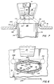
- Figure 6 shows a tube end 166 and the area surrounding the manifold by a top view while Figure 7 is a side view.
- the collector 74 has an orifice or collar 168 of generally oval shape formed in its wall.
- the end of the tube 166 protrudes through this orifice and its tubular wall 174 forms an assembly joint to be welded 172 with the edge 173 of the part cut upwards from the manifold 74. It is understood that, taking into account the precise orientation given to the tube end 166, the tubular wall 174 will probably touch the edge 173 at numerous points.
- the active welding area of the arc 206 is represented by the circle 212, the diameter of which is shown in 214. It is understood that the welding arc currently described may not have this configuration, it is taken here to facilitate the description. If the welding head 92 were moved only in the direction of the arrow 216, the welding surface created would have only a width roughly equivalent to that of the circle of diameter 214. But, by the action of the coil 99 which, at the same time, imposes on the arc 206 a reciprocating or oscillating movement back and forth in the directions-there imparting a sweeping movement indicated by the arrow 218, a larger welding surface 213 and a strip of welding generally mentioned by the reference 214 can be produced. As the welding head 92 is thus moved in the x-direction, an enlarged welding strip is formed. Therefore, a whole row of tube ends as seen in FIG. 2 can be welded by a single pass of the welding head 92.
- the amplitude control 120 of the recording device 98 can be used to vary the density of the magnetic flux; the speed control 124 makes it possible to adjust the frequency at which the arc oscillates or sweeps transversely; the right and left stop controls 126 and 122 adjust the momentary stop times or exposure times to the respective extreme right and left positions 220 and 222.
- the length 224 of the welding strip created by the welding head 92 can easily be changed.
- the welding strip 224 can be reduced by half, two passages of the head then being necessary for each row. It is also possible, if desired, to adjust the passages so as to provide an overlap in the weld flows.
- the correct welding current to be supplied by the energy source 94 is chosen by the control command 128.
- Sweep welding of different radiator bodies made of different sizes and materials requires specific operating parameters of the device. It has been found that for manifolds and tube ends made of brass (practically about 70% copper and 30% zinc), with manifold thicknesses practically between 0.762 and 1.270 mm (0.030 and 0.050 inch) and thicknesses side wall of tube practically between 0.178 and 0.229 mm (0.007 and 0.009 inch), the displacement speed of the welding head must be between 2.226 and 3.048 mm (90 to 120 inches) per minute and that the current between 150 and 160 amps at a voltage of approximately 33 volts peak-to-peak, with a welding gap of approximately 15.88 mm (5/8 inch). The lateral oscillation frequency and the value of the stopping times are adjusted to obtain a suitable weld along a welding strip of a chosen length.
- the welding current is of the order of 75 to 80 amperes under a voltage of 18 to 20 volts peak to peak and a displacement speed of the welding head of approximately 2.226 mm (90 inches) per minute.
- radiator bodies for an automobile produced by the method and the apparatus, objects of the present invention are produced more efficiently and more quickly than by the tracing welding method of the current technique; that the bodies welded by sweep have better results in thermal and pressure tests; that the metallographic integrity of the weld produced is thereby improved; and that the need for additional filling by adding tin to the air side of the collector is reduced in the case of collectors welded by sweeping.
- radiator bodies welded by sweeping without the addition of tin on the air side were subjected to thermal tests and cycled between 12 and 90 ° C (55 and 195 degrees Fahrenheit) at a frequency of 40 cycles per hour.
- the two bodies underwent 4.490 cycles without leakage at the time when the tests were stopped.
- the classic industrial specifications are only 3,000 cycles without leakage.
- a radiator body welded according to the current tracing method would have required an additional supply of solder to achieve such thermal resistance.
- the scanning welding method of the present invention can be executed with both an inert metallic gas (MIG) and a Tungsten inert gas environment.
- MIG inert metallic gas
- Tungsten inert gas environment a metallic gas
- the preferred embodiment uses a magnetic control of the arc for the transverse reciprocating movement, it is just as possible to obtain this rocking movement from one side to the other by other means, such as mechanical means. for example. If such mechanical means are used, an acetylene welding method can also be used.
Landscapes
- Engineering & Computer Science (AREA)
- Physics & Mathematics (AREA)
- Mechanical Engineering (AREA)
- Plasma & Fusion (AREA)
- Thermal Sciences (AREA)
- General Engineering & Computer Science (AREA)
- Butt Welding And Welding Of Specific Article (AREA)
- Arc Welding In General (AREA)
- Arc Welding Control (AREA)
Claims (12)
- Verfahren zum Schweißen einer Gesamtheit von Rohren an einer Rohrplatte (12, 42, 72), bei dem ein Rohrende (14, 40, 76), das aus dem Ende des Rohrs besteht, durch eine Öffnung der besagten Platte vorsteht, um eine Verbindungsfuge (16, 50) zu bilden, um das besagte Rohr an der besagten Platte in der Zone der besagten Öffnung zu verschweißen, wobei das besagte Verfahren die folgenden Phasen umfaßt:a) Bewegung eines Lichtbogens (18, 56) in einer ausgewählten Richtung (26) entlang einem Weg, der zu durchlaufen ist, um eine Schweißverbindung entlang den besagten Verbindungsfugen auszuführen, wo der besagte Lichtbogen die besagten Verbindungsfugen berührt;b) gleichzeitig mit Phase (a) erfolgende Führung des Lichtbogens in einer Pendelbewegung von vorn nach hinten in einer Richtung (28), die senkrecht im Verhältnis zu der besagten ausgewählten Richtung verläuft, mit einer ausreichenden Amplitude (30, 32) der Pendelbewegung, um wenigstens einen Teil der besagten Verbindungsfuge zu erreichen, der wenigstens auf einer Seite des besagten Wegs angeordnet ist, um zusätzlich eine Schweißfläche entlang der besagten Fuge zu bilden, während sich der besagte Lichtbogen in der besagten ausgewählten Richtung bewegt, wodurch die Schweißung wenigstens eines Teils der besagten Fuge sowohl auf der Seite als auch längs des besagten Wegs erfolgen kann;c) Führung des Lichtbogens (18, 56) in einer Pendelbewegung beiderseits des besagten Wegs mit einer ausreichenden Amplitude, um die besagte Fuge vollständig um das besagte Rohrende herum zu verschweißen, wobei das besagte Rohr um eine Mittelachse (38) gebildet ist und wobei der besagte Weg allgemein zentriert ist, so daß er durch die besagte Achse verläuft, die an das besagte Rohrende angrenzt.
- Verfahren nach Anspruch 1, bei dem eine Gesamtheit von Rohren mit einem durch die besagte Platte (12, 42, 72) vorstehenden Rohrende (14, 40, 76) an der besagten Platte verschweißt werden soll und bei dem der besagte Weg so gewählt wird, daß der besagte Lichtbogen (18, 56) die besagten Rohrenden nacheinander berühren kann.
- Verfahren nach einem der Ansprüche 1 oder 2, bei dem die besagte Gesamtheit von Rohren eine regelmäßige Anordnung bildet und bei dem der besagte Weg so gewählt wird, daß er der besagten Anordnung entspricht, damit der besagte Lichtbogen (18, 56) nacheinander die besagten Rohrenden (14, 40, 76) berühren kann.
- Verfahren nach einem der vorangehenden Ansprüche, bei dem die besagten Rohrenden (14, 40, 76) in einer rechteckigen Anordnung mit Bildung einer Gesamtheit von Rohrendenreihen (44, 46, 48) angeordnet sind und bei dem der besagte Weg so gewählt wird, daß sich der besagte Lichtbogen (18, 56) entlang einer ersten Reihe und anschließend nacheinander entlang den anderen Reihen bewegt, wobei die besagte Amplitude ausreichend ist, damit jedes Rohrende an der besagten Platte vollständig um jede Verbindungsfuge (16, 50) herum verschweißt wird.
- Verfahren nach einem der vorangehenden Ansprüche, bei dem die besagte Pendelbewegungsphase mit einer Phase zur Anwendung eines veränderlichen Magnetfelds auf den besagten Lichtbogen einhergeht.
- Verfahren zum Schweißen einer Rohrreihe nach einen der vorangehenden Ansprüche, bei dem der Lichtbogen (18, 56) durch einen Lichtbogenbrenner (92) erzeugt wird, der sich entlang einem Weg bewegt, auf dem er die besagten Rohrenden (14, 40, 76) nacheinander von einer Ausgangsposition bis zu einer Endposition für die besagte Rohrreihe berühren kann, während ein elektrischer Strom zwischen dem besagten Brenner und der besagten Rohrreihe fließt, um einen ausreichenden Schweißlichtbogen zum Schweißen der besagten Fugen zu erzeugen, wobei der besagte Lichtbogen wenigstens einen Teil der besagten Fugen entlang dem besagten Weg berührt, um die besagten Rohrenden am Sammler auf einer Schweißbandbreite in der Nähe des besagten Wegs zu verschweißen, und wobei gleichzeitig mit der besagten Bewegung (a) ein Magnetfeld im Bereich des besagten Lichtbogens angewendet wird, um die besagte Schweißbandbreite zu regeln.
- Verfahren nach einem der Ansprüche 1 bis 6, bei dem die besagte Anordnung wenigstens eine Reihe von Rohrenden (44, 46, 48) enthält, wobei die besagte Reihe allgemein parallel zur x-Richtung in einer x/y-Ebene verlaufen kann, wobei die besagte Reihe eine Reihenbreite in y-Richtung aufweist und wobei das besagte Verfahren zusätzlich die folgenden Phasen umfaßt:(a) Bewegung des besagten Schweißbrenners (92) entlang einem ausgewählten Weg in x-Richtung, beginnend mit dem ausgewählten ersten Rohr der besagten Reihe und endend mit dem ausgewählten letzten Rohr der besagten Reihe, wobei das besagte Magnetfeld eine Flußdichte besitzt, die so gewählt wird, daß eine Schweißbandbreite entsteht, die sich auf einem Teil der besagten ausgewählten Reihe erstreckt;(b) nach der Berührung des letzten ausgewählten Rohres erfolgende Steuerung des besagten Schweißbrenners (92) in y-Richtung bis zu einem bestimmten ausgewählten Abstand;(c) nach dieser Steuerung erfolgende Bewegung des besagten Schweißbrenners (92) entlang dem folgenden Weg, der praktisch parallel zu dem besagten ersten Weg verläuft, aber in y-Richtung um den besagten ausgewählten Abstand versetzt ist, um die besagten Fugen in dem folgenden Schweißband zu schweißen, das in y-Richtung um den besagten ausgewählten Abstand versetzt ist;(d) Fortführung dieser Bewegung des Schweißbrenners (92) in x-Richtung an den besagten Rohrenden (14, 40, 74) und erneut Steuerung des besagten Schweißbrenners in y-Richtung nach jedem so zurückgelegten Weg, wobei die besagten Fugen auf der Breite der besagten Reihen geschweißt werden.
- Verfahren nach Anspruch 7, bei dem der Schweißbrenner (92) in entgegengesetzter Richtung nach jeder Phase zur Bewegungssteuerung des Brenners um einen ausgewählten Abstand bewegt wird, um den Brenner von vorn nach hinten über den besagten Rohrenden (14, 40, 76) schwingen zu lassen.
- Verfahren nach Anspruch 8, bei dem sich das besagte Schweißband, das zu einem ersten Weg gehört, mit einem Schweißband überlagert, das zum folgenden Weg in entgegengesetzter Richtung gehört.
- Verfahren nach Anspruch 7, bei dem die Breite des besagten Schweißbands durch die Anwendung des besagten Magnetfelds im Verhältnis zur Breite der Reihen der besagten Rohrenden geregelt wird, um die besagten Fugen in einer einzigen Ablenkung von vorn nach hinten zu schweißen.
- Verfahren nach Anspruch 8 oder 9, bei dem die besagte Anordnung außerdem eine Gesamtheit von parallelen Rohrendenreihen enthält, die in Kolonnen angeordnet sind, wobei die besagten Reihen in x-Richtung und die besagten Kolonnen in y-Richtung verlaufen und wobei das besagte Verfahren zusätzlich die folgenden Phasen umfaßt:(a) Steuerung des besagten Schweißbrenners (92) zur folgenden Reihe in y-Richtung, nachdem die vorangehende Reihe geschweißt worden ist;(b) Ausführung der besagten Bewegung von vorn nach hinten an der besagten folgenden Reihe;(c) Fortführung der Phasen (a) und (b), bis die besagten Reihen und die besagten Kolonnen von Rohrenden verschweißt sind.
- Verfahren nach den vorangehenden Ansprüchen, bei dem das besagte Rohrende (14, 40, 76) einen ovalen Querschnitt besitzt, wobei das besagte Oval einen großen und einen kleinen Außendurchmesser aufweist, und mit einer Gesamtheit von Rohren in einer rechteckigen Anordnung mit drei Reihen (44, 46, 48), wobei jede Reihe eine Breite hat, die allgemein dem großen Durchmesser des besagten Ovals entspricht, und wobei die besagte Bewegungsphase die Phase zur Bewegung der besagten Elektrode entlang einer ausgewählten der besagten Reihen enthält, ausgehend von einem ersten ausgewählten Ende der besagten Reihe bis zum letzten ausgewählten Rohrende der besagten Reihe in einer Richtung, die dem kleinen Außendurchmesser der besagten Rohrenden entspricht, und wobei der besagte Lichtbogen von vorn nach hinten in ausreichenden Abständen bewegt wird, um den besagten großen Durchmesser abzudecken und jedes der besagten Rohre am Sammler in Höhe des besagten Umfangs in einem einzigen Durchgang der besagten Elektrode in Höhe des besagten Rohrendes zu verschweißen.
Applications Claiming Priority (2)
| Application Number | Priority Date | Filing Date | Title |
|---|---|---|---|
| US397102 | 1989-08-21 | ||
| US07/397,102 US4965431A (en) | 1989-08-21 | 1989-08-21 | Sweep welding method and apparatus therefor |
Publications (2)
| Publication Number | Publication Date |
|---|---|
| EP0414595A1 EP0414595A1 (de) | 1991-02-27 |
| EP0414595B1 true EP0414595B1 (de) | 1996-05-22 |
Family
ID=23569833
Family Applications (1)
| Application Number | Title | Priority Date | Filing Date |
|---|---|---|---|
| EP90402305A Expired - Lifetime EP0414595B1 (de) | 1989-08-21 | 1990-08-17 | Verfahren zum Schweissen durch Lichtbogenablenkung |
Country Status (5)
| Country | Link |
|---|---|
| US (1) | US4965431A (de) |
| EP (1) | EP0414595B1 (de) |
| JP (1) | JPH0394976A (de) |
| CA (1) | CA2022244A1 (de) |
| DE (1) | DE69027072T2 (de) |
Families Citing this family (12)
| Publication number | Priority date | Publication date | Assignee | Title |
|---|---|---|---|---|
| US5036913A (en) * | 1990-11-05 | 1991-08-06 | Valeo Engine Cooling, Incorporated | Vehicle radiator with tube to header joint formed of a composite weld and solder bond |
| DE4343825A1 (de) * | 1993-12-22 | 1995-06-29 | Behr Gmbh & Co | Rohr-Bodenverbindung für einen Wärmetauscher |
| US5552575A (en) * | 1994-07-15 | 1996-09-03 | Tufts University | Scan welding method and apparatus |
| GB2316902B (en) * | 1996-09-06 | 2000-11-29 | Rolls Royce Plc | Welding torch |
| US5904864A (en) * | 1997-11-26 | 1999-05-18 | Baltimore Aircoil Company, Inc. | Robotic welding |
| CN1222395C (zh) * | 2003-08-19 | 2005-10-12 | 潘际銮 | 永磁履带自主全位置爬行式弧焊机器人的控制方法 |
| DE102011075071A1 (de) * | 2011-05-02 | 2012-11-08 | Behr Gmbh & Co. Kg | Wärmetauscher, insbesondere Ladeluftkühler |
| DK177774B1 (en) | 2013-04-11 | 2014-06-23 | Spx Flow Technology Danmark As | HYGIENIC HEAT EXCHANGE AND METHOD FOR PREPARING A HYGIENIC HEAT EXCHANGE |
| US9981584B2 (en) | 2014-10-29 | 2018-05-29 | Toyota Motor Engineering & Manufacturing North America, Inc. | Method of reinforcing a seatback frame of a seat assembly |
| CN105458468B (zh) * | 2015-12-29 | 2018-02-16 | 江西鑫田车业有限公司 | 焊接设备 |
| DE102019130644A1 (de) * | 2019-11-13 | 2021-05-20 | Endress+Hauser Flowtec Ag | Verwendung eines Lichtbogenschweißgeräts umfassend eine Richtapparatur |
| CN112894360B (zh) * | 2021-01-14 | 2022-04-15 | 创际建工集团有限公司 | 一种建筑施工用管材焊接装置 |
Family Cites Families (19)
| Publication number | Priority date | Publication date | Assignee | Title |
|---|---|---|---|---|
| US2743342A (en) * | 1952-04-15 | 1956-04-24 | Edward S Bettis | Magnetic arc-welder |
| US3675841A (en) * | 1969-09-30 | 1972-07-11 | Friedrich Gutlhuber | Apparatus for automatic execution of machining operations, such as welding |
| US3626145A (en) * | 1970-02-02 | 1971-12-07 | Armco Steel Corp | Magnetic control of arc environment |
| AT317641B (de) * | 1972-09-07 | 1974-09-10 | Simmering Graz Pauker Ag | Verfahren und Vorrichtung zum elektrischen Lichtbogenschweißen |
| JPS5142058B2 (de) * | 1973-05-24 | 1976-11-13 | ||
| CH591306A5 (de) * | 1975-01-27 | 1977-09-15 | Secheron Soudure Sa | |
| US4278868A (en) * | 1977-12-19 | 1981-07-14 | Thermatool Corp. | Methods and apparatus for heating metal parts with magnetically driven travelling electric arc |
| US4219722A (en) * | 1977-12-19 | 1980-08-26 | Thermatool Corp. | Methods and apparatus for heating metal parts with magnetically driven travelling electric arc |
| DE2805562C2 (de) * | 1978-02-10 | 1984-08-02 | Kuka Schweissanlagen + Roboter Gmbh, 8900 Augsburg | Vorrichtung zum Anschweißen eines Werkstücks mit rohrförmigem Querschnitt an der Schweißstelle an ein zweites Werkstück |
| US4529034A (en) * | 1979-12-20 | 1985-07-16 | Modine Manufacturing Company | Heat exchanger having a header plate |
| US4303823A (en) * | 1980-01-24 | 1981-12-01 | Modine Manufacturing Company | Welding device |
| US4319113A (en) * | 1980-05-09 | 1982-03-09 | Westinghouse Electric Corp. | Apparatus for welding tubes to a tubesheet utilizing a continuous weld |
| DE3165991D1 (en) * | 1980-07-14 | 1984-10-18 | Westinghouse Electric Corp | Method for continuously welding a plurality of tubes disposed in multiple rows to a tube sheet |
| FR2488823A1 (fr) * | 1980-08-19 | 1982-02-26 | Framatome Sa | Procede de soudage |
| US4376886A (en) * | 1981-01-02 | 1983-03-15 | Sciaky Bros., Inc. | Method for electron beam welding |
| FR2504041B1 (fr) * | 1981-04-15 | 1986-01-10 | Kuka Schweissanlagen & Roboter | Dispositif pour souder des pieces metalliques longues, au moyen d'un arc devie par un champ magnetique |
| DE3209233C2 (de) * | 1981-04-15 | 1984-06-07 | Kuka Schweissanlagen + Roboter Gmbh, 8900 Augsburg | Vorrichtung zum Verschweißen von metallischen Werkstücken |
| US4511784A (en) * | 1983-04-15 | 1985-04-16 | Nippon Kokan Koji Kabushiki Kaisha | Method for welding by magnetically driven arc |
| US4744505A (en) * | 1983-10-19 | 1988-05-17 | The Allen Group, Inc. | Method of making a heat exchanger |
-
1989
- 1989-08-21 US US07/397,102 patent/US4965431A/en not_active Expired - Lifetime
-
1990
- 1990-07-30 CA CA002022244A patent/CA2022244A1/en not_active Abandoned
- 1990-08-17 DE DE69027072T patent/DE69027072T2/de not_active Expired - Fee Related
- 1990-08-17 EP EP90402305A patent/EP0414595B1/de not_active Expired - Lifetime
- 1990-08-20 JP JP2217250A patent/JPH0394976A/ja active Pending
Also Published As
| Publication number | Publication date |
|---|---|
| DE69027072D1 (de) | 1996-06-27 |
| DE69027072T2 (de) | 1996-10-02 |
| EP0414595A1 (de) | 1991-02-27 |
| CA2022244A1 (en) | 1991-02-22 |
| JPH0394976A (ja) | 1991-04-19 |
| US4965431A (en) | 1990-10-23 |
Similar Documents
| Publication | Publication Date | Title |
|---|---|---|
| US9272369B2 (en) | Method for automated superalloy laser cladding with 3D imaging weld path control | |
| EP1574279B1 (de) | Laserbearbeitungsvorrichtung | |
| EP0414595A1 (de) | Verfahren zum Schweissen durch Lichtbogenablenkung | |
| CN105583523B (zh) | 一种超声辅助激光深熔焊接板材的方法 | |
| EP0130100B1 (de) | Verfahren zum Laserstrahlpunktschweissen | |
| US20140069893A1 (en) | Automated superalloy laser cladding with 3d imaging weld path control | |
| CN106141435A (zh) | 激光电弧复合焊3d增材修补装置及修补方法 | |
| KR20050062394A (ko) | 레이저 용접을 위한 방법 및 장치 | |
| Zhu et al. | Tailoring droplet transfer and molten pool flow during hybrid laser arc welding of nickel base alloy | |
| GB2169834A (en) | Apparatus and method for weld cladding cylindrical objects | |
| US20240375218A1 (en) | Method for depositing molten metal filament using a laser beam swept across the surface of the workpiece | |
| CN115194332A (zh) | 用于曲线焊缝的激光-tig电弧复合焊接装置及方法 | |
| Zhu et al. | Joint penetration monitoring in low-frequency pulsed GTA root pass welding of medium-thick steel plates | |
| EP1960148B1 (de) | Automatische mig/mag schweissvorrichtung | |
| CN105904078A (zh) | 电子束变焦焊方法及系统 | |
| JP2006205171A (ja) | 溶接装置及びそれを用いた溶接方法 | |
| JPH06234089A (ja) | レーザシーム溶接機 | |
| CN205684898U (zh) | 电子束变焦焊系统 | |
| JP3153168B2 (ja) | ウォータロッド・タブ溶接方法 | |
| KR102727301B1 (ko) | 포터블 소켓 및 분기배관 오비탈 용접장치 | |
| US3902038A (en) | Displaced electrode process for welding | |
| Viri | CRBRP modular steam generator tube-to-tubesheet and shell-closure welding | |
| CN114012264A (zh) | 金属构件焊接方法及金属构件 | |
| KR101160981B1 (ko) | 플럭스 코어드 와이어 제조 장치 | |
| JPS639911B2 (de) |
Legal Events
| Date | Code | Title | Description |
|---|---|---|---|
| PUAI | Public reference made under article 153(3) epc to a published international application that has entered the european phase |
Free format text: ORIGINAL CODE: 0009012 |
|
| AK | Designated contracting states |
Kind code of ref document: A1 Designated state(s): DE FR GB IT SE |
|
| 17P | Request for examination filed |
Effective date: 19910411 |
|
| 17Q | First examination report despatched |
Effective date: 19920929 |
|
| GRAH | Despatch of communication of intention to grant a patent |
Free format text: ORIGINAL CODE: EPIDOS IGRA |
|
| GRAA | (expected) grant |
Free format text: ORIGINAL CODE: 0009210 |
|
| RAP1 | Party data changed (applicant data changed or rights of an application transferred) |
Owner name: VALEO ENGINE COOLING, INC. |
|
| AK | Designated contracting states |
Kind code of ref document: B1 Designated state(s): DE FR GB IT SE |
|
| REF | Corresponds to: |
Ref document number: 69027072 Country of ref document: DE Date of ref document: 19960627 |
|
| ITF | It: translation for a ep patent filed | ||
| GBT | Gb: translation of ep patent filed (gb section 77(6)(a)/1977) |
Effective date: 19960806 |
|
| PLBE | No opposition filed within time limit |
Free format text: ORIGINAL CODE: 0009261 |
|
| STAA | Information on the status of an ep patent application or granted ep patent |
Free format text: STATUS: NO OPPOSITION FILED WITHIN TIME LIMIT |
|
| 26N | No opposition filed | ||
| PGFP | Annual fee paid to national office [announced via postgrant information from national office to epo] |
Ref country code: GB Payment date: 19980811 Year of fee payment: 9 |
|
| PGFP | Annual fee paid to national office [announced via postgrant information from national office to epo] |
Ref country code: FR Payment date: 19980821 Year of fee payment: 9 |
|
| PG25 | Lapsed in a contracting state [announced via postgrant information from national office to epo] |
Ref country code: GB Free format text: LAPSE BECAUSE OF NON-PAYMENT OF DUE FEES Effective date: 19990817 |
|
| GBPC | Gb: european patent ceased through non-payment of renewal fee |
Effective date: 19990817 |
|
| PG25 | Lapsed in a contracting state [announced via postgrant information from national office to epo] |
Ref country code: FR Free format text: LAPSE BECAUSE OF NON-PAYMENT OF DUE FEES Effective date: 20000428 |
|
| REG | Reference to a national code |
Ref country code: FR Ref legal event code: ST |
|
| PG25 | Lapsed in a contracting state [announced via postgrant information from national office to epo] |
Ref country code: IT Free format text: LAPSE BECAUSE OF NON-PAYMENT OF DUE FEES;WARNING: LAPSES OF ITALIAN PATENTS WITH EFFECTIVE DATE BEFORE 2007 MAY HAVE OCCURRED AT ANY TIME BEFORE 2007. THE CORRECT EFFECTIVE DATE MAY BE DIFFERENT FROM THE ONE RECORDED. Effective date: 20050817 |
|
| PGFP | Annual fee paid to national office [announced via postgrant information from national office to epo] |
Ref country code: DE Payment date: 20080811 Year of fee payment: 19 |
|
| PGFP | Annual fee paid to national office [announced via postgrant information from national office to epo] |
Ref country code: SE Payment date: 20080722 Year of fee payment: 19 |
|
| PG25 | Lapsed in a contracting state [announced via postgrant information from national office to epo] |
Ref country code: DE Free format text: LAPSE BECAUSE OF NON-PAYMENT OF DUE FEES Effective date: 20100302 |
|
| PG25 | Lapsed in a contracting state [announced via postgrant information from national office to epo] |
Ref country code: SE Free format text: LAPSE BECAUSE OF NON-PAYMENT OF DUE FEES Effective date: 20090818 |