EP0414603A1 - Betätigungseinrichtung für eine Steueranlage mit Bowdenzug - Google Patents
Betätigungseinrichtung für eine Steueranlage mit Bowdenzug Download PDFInfo
- Publication number
- EP0414603A1 EP0414603A1 EP90402321A EP90402321A EP0414603A1 EP 0414603 A1 EP0414603 A1 EP 0414603A1 EP 90402321 A EP90402321 A EP 90402321A EP 90402321 A EP90402321 A EP 90402321A EP 0414603 A1 EP0414603 A1 EP 0414603A1
- Authority
- EP
- European Patent Office
- Prior art keywords
- lever
- cable
- housing
- rod
- control system
- Prior art date
- Legal status (The legal status is an assumption and is not a legal conclusion. Google has not performed a legal analysis and makes no representation as to the accuracy of the status listed.)
- Withdrawn
Links
- 238000003754 machining Methods 0.000 description 2
- 238000004519 manufacturing process Methods 0.000 description 2
- 238000000034 method Methods 0.000 description 2
- 230000000295 complement effect Effects 0.000 description 1
- 238000006073 displacement reaction Methods 0.000 description 1
- 238000000465 moulding Methods 0.000 description 1
- 230000007935 neutral effect Effects 0.000 description 1
Images

Classifications
-
- F—MECHANICAL ENGINEERING; LIGHTING; HEATING; WEAPONS; BLASTING
- F16—ENGINEERING ELEMENTS AND UNITS; GENERAL MEASURES FOR PRODUCING AND MAINTAINING EFFECTIVE FUNCTIONING OF MACHINES OR INSTALLATIONS; THERMAL INSULATION IN GENERAL
- F16C—SHAFTS; FLEXIBLE SHAFTS; ELEMENTS OR CRANKSHAFT MECHANISMS; ROTARY BODIES OTHER THAN GEARING ELEMENTS; BEARINGS
- F16C1/00—Flexible shafts; Mechanical means for transmitting movement in a flexible sheathing
- F16C1/10—Means for transmitting linear movement in a flexible sheathing, e.g. "Bowden-mechanisms"
- F16C1/12—Arrangements for transmitting movement to or from the flexible member
-
- F—MECHANICAL ENGINEERING; LIGHTING; HEATING; WEAPONS; BLASTING
- F16—ENGINEERING ELEMENTS AND UNITS; GENERAL MEASURES FOR PRODUCING AND MAINTAINING EFFECTIVE FUNCTIONING OF MACHINES OR INSTALLATIONS; THERMAL INSULATION IN GENERAL
- F16C—SHAFTS; FLEXIBLE SHAFTS; ELEMENTS OR CRANKSHAFT MECHANISMS; ROTARY BODIES OTHER THAN GEARING ELEMENTS; BEARINGS
- F16C1/00—Flexible shafts; Mechanical means for transmitting movement in a flexible sheathing
- F16C1/10—Means for transmitting linear movement in a flexible sheathing, e.g. "Bowden-mechanisms"
- F16C1/12—Arrangements for transmitting movement to or from the flexible member
- F16C1/16—Arrangements for transmitting movement to or from the flexible member in which the end-piece is guided rectilinearly
-
- G—PHYSICS
- G05—CONTROLLING; REGULATING
- G05G—CONTROL DEVICES OR SYSTEMS INSOFAR AS CHARACTERISED BY MECHANICAL FEATURES ONLY
- G05G5/00—Means for preventing, limiting or returning the movements of parts of a control mechanism, e.g. locking controlling member
- G05G5/05—Means for returning or tending to return controlling members to an inoperative or neutral position, e.g. by providing return springs or resilient end-stops
-
- G—PHYSICS
- G05—CONTROLLING; REGULATING
- G05G—CONTROL DEVICES OR SYSTEMS INSOFAR AS CHARACTERISED BY MECHANICAL FEATURES ONLY
- G05G7/00—Manually-actuated control mechanisms provided with one single controlling member co-operating with one single controlled member; Details thereof
- G05G7/02—Manually-actuated control mechanisms provided with one single controlling member co-operating with one single controlled member; Details thereof characterised by special provisions for conveying or converting motion, or for acting at a distance
Definitions
- the present invention relates to an operating device for cable sheath control system.
- such a device comprises a housing, fixed within the reach of an operator, to which the cable / sheath assembly leads, which is also connected to a member to be controlled, for example a hydraulic distributor, a lever pivotally mounted on the housing and actuable by hand, and a mechanical connection between the lever and the cable of the control system.
- Known devices usually have two drawbacks: - the cable / sheath assembly is connected through the lower part of the housing, thus forcing the cable / sheath assembly to be extended and making it pass through a loop to allow such a connection; -
- the mechanical connection between the lever and the cable consists of a connecting rod attached with articulation on the one hand to the cable end piece and, on the other hand, to a lateral arm secured to the lever. It follows from the circular path of the lateral arm of the lever that the forces transmitted to the cable are not purely longitudinal and comprise undesirable transverse components which generate wear.
- the ratio between the force applied to the lever and the force applied to the cable varies approximately sinusoidally.
- the present invention provides an operating device of the type specified above, characterized in that it comprises a control rod connected to the cable and guided in translation back and forth in the extension of the cable. , a lateral rack secured to said rod, and a toothed sector secured to said lever, in mesh with said rack.
- connection of the cable / sheath assembly is located laterally on the housing, by placing the rod horizontally in the housing.
- the device according to the invention can be completed in a simple manner by two adjustable stop members limiting the tilting of the lever in one or the other direction.
- these adjustable stop members will consist of two screws engaged in the housing and cooperating with the toothed sector integral with the lever.
- the lever and the toothed sector came in one piece.
- the rack can be formed directly on the rod.
- the machining operations may be limited to a reduced number of simple operations, like boring a hole or dressing a bearing face.
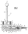
- the device 10 comprises a housing 12 consisting for example of two halves symmetrical with respect to the plane of the figure.
- the housing has forms of slide 14 by which it can be engaged on a form of complementary rail.
- a manual operating lever 16 is pivotally mounted in the housing around an axis 18 and comprises an arm 20 which projects substantially vertically upwards out of the housing and within reach of an operator when the device is mounted on its support.
- the lever has an extension 22 provided at its periphery with a toothed sector 24 of a certain angular extent around the axis 18 and in a manner substantially symmetrical with respect to the 'middle axis XX of the arm 20 of the lever.
- the toothed sector 24 meshes with a rack 26 formed laterally on the tail 28 of a rod 30 which extends substantially horizontally in the housing 12 and perpendicular to the arm 20 of the lever 16.
- the rod 30 is guided in the housing 12 so as to be able to move therein back and forth, that is to say to the left or the right in the figure, only in the direction of its longitudinal axis YY .
- the central part 32 of the rod receives a device 34 with return spring in the centered position, with double action.
- This device comprises a spring 36 surrounding the rod and contained between two washers 38, 40 bearing on two shoulders of the rod, a shoulder 42 formed on the rod itself on the side of its tail 28 and a shoulder 44 formed by a rod surrounding the stem.
- the two washers are also in abutment against two opposite shoulders 46, 48 of the housing.
- This well-known device makes it possible to bring the rod back to a central position, as illustrated in the figure, in which the lever is returned to a generally vertical orientation when, after having tilted the lever in one direction or the other, it is released.
- the rod comprises attachment means 52 intended to receive an end piece 54 fixed to the end of a cable 56 movable back and forth in a sheath 58.
- the housing Around the end 50 of the rod, the housing includes a housing 60 intended to receive an end piece 62 fixed to the end of the sheath 58, the latter being locked by any conventional means, for example a transverse pin 64 as illustrated.
- the housing On either side of the axis 18 of the lever 16 the housing has two legs 66, 68 on which are fixed adjustable stop screws 70, 72 making it possible to limit the tilting of the lever 16 in one direction or the other respectively.
- the toothed sector 24 of the lower extension 22 of the lever comprises two flanks 74, 76 intended to come into abutment against the screws 70, 72 in the direction of tilting of the lever.
- a sliding plate 78 made of an appropriate material in order to reduce the friction between the housing and the rod during movements of the latter. Ci back and forth and if necessary constitute a replaceable wear part.
- the ratio between the force applied to the arm 20 of the lever and the force transmitted to the cable 58 remains constant during the tilting of the lever.
- the washer 40 compresses the return spring 36 against the shoulder 46 of the housing, so that the spring returns the rod to the centered position in the figure and the lever arm in vertical orientation when we release the latter.
- the return spring device in the centered position is composed of two spiral springs which cooperate with the lever 16 as will be described below.
- the spring 80 is wound around a boss 82 provided laterally on the lever around the axis 18 and has two tabs 84, 86, at its two ends, one of the tabs 84 bearing against a stud 88 of the housing 12 and the other 86 against a pin 90 of the lever.
- the other spring is arranged symmetrically, its legs bearing on corresponding pins of the housing and the lever, but in the opposite direction.
- This variant will reduce the length of the body.
- connection of the cable and the sheath being effected laterally on the body, it will thus be possible to provide a clearly more direct path for the cable / sheath assembly towards a member not shown controlled at the other end of the cable / sheath assembly .
- Relatively simple manufacturing techniques can be used to make the various parts of the device.
- molding techniques possibly under pressure, make it possible to obtain practically finished parts and to limit subsequent machining operations.
Landscapes
- Engineering & Computer Science (AREA)
- General Engineering & Computer Science (AREA)
- Health & Medical Sciences (AREA)
- Oral & Maxillofacial Surgery (AREA)
- Mechanical Engineering (AREA)
- Physics & Mathematics (AREA)
- General Physics & Mathematics (AREA)
- Automation & Control Theory (AREA)
- Flexible Shafts (AREA)
- Mechanical Control Devices (AREA)
Applications Claiming Priority (2)
| Application Number | Priority Date | Filing Date | Title |
|---|---|---|---|
| FR8911075A FR2651048B1 (fr) | 1989-08-21 | 1989-08-21 | Dispositif de manoeuvre pour systeme de commande a cable sous gaine |
| FR8911075 | 1989-08-21 |
Publications (1)
| Publication Number | Publication Date |
|---|---|
| EP0414603A1 true EP0414603A1 (de) | 1991-02-27 |
Family
ID=9384818
Family Applications (1)
| Application Number | Title | Priority Date | Filing Date |
|---|---|---|---|
| EP90402321A Withdrawn EP0414603A1 (de) | 1989-08-21 | 1990-08-21 | Betätigungseinrichtung für eine Steueranlage mit Bowdenzug |
Country Status (2)
| Country | Link |
|---|---|
| EP (1) | EP0414603A1 (de) |
| FR (1) | FR2651048B1 (de) |
Cited By (9)
| Publication number | Priority date | Publication date | Assignee | Title |
|---|---|---|---|---|
| EP0519811A1 (de) * | 1991-06-19 | 1992-12-23 | Telecommandes Mecaniques Par Cable T.M.C. | Bowdenzugsteuergehäuse |
| EP0611903A1 (de) * | 1993-02-18 | 1994-08-24 | Ford-Werke Aktiengesellschaft | Wählhebelanordnung für ein automatisches Getriebe eines Kraftfahrzeuges |
| EP0659964A1 (de) * | 1993-12-20 | 1995-06-28 | Mecaplast Sam | Seilbetätigungsvorrichtung mit mindestens einem Betätigungshebel |
| WO1996000339A1 (fr) * | 1994-06-23 | 1996-01-04 | Mecaplast S.A.M. | Dispositif de positionnement a distance d'un mecanisme a trois positions |
| US5509326A (en) * | 1992-12-03 | 1996-04-23 | Rockwell Body And Chassis Systems | Parking brake for motor vehicle with a low application force |
| WO1997047439A1 (de) * | 1996-06-10 | 1997-12-18 | Carlos Santos Marques | Motorbetriebenes handgerät für haushalt und gewerbe |
| FR2821132A1 (fr) * | 2001-02-20 | 2002-08-23 | Sila Holding Ind | Dispositif de manoeuvre d'un cable de commande a came helicoidale comprenant des moyens de reglage de la longueur de la gaine |
| FR2822507A1 (fr) * | 2001-03-26 | 2002-09-27 | Sila Holding Ind | Dispositif de manoeuvre d'un cable de commande a came helicoidale |
| FR2928185A1 (fr) * | 2008-02-28 | 2009-09-04 | Peugeot Citroen Automobiles Sa | Embout de liaison pour cable d'actionnement coulissant dans une gaine |
Families Citing this family (1)
| Publication number | Priority date | Publication date | Assignee | Title |
|---|---|---|---|---|
| CN103615527B (zh) * | 2013-12-02 | 2016-03-30 | 洛阳市黄河软轴控制器股份有限公司 | 单手柄式多功能操纵机构 |
Citations (6)
| Publication number | Priority date | Publication date | Assignee | Title |
|---|---|---|---|---|
| GB464686A (en) * | 1935-10-19 | 1937-04-19 | Rene Tampier | Improvements in hand control levers for the carburetter throttles of internal combustion engines |
| US3543602A (en) * | 1968-11-25 | 1970-12-01 | Robert D Riedle | Lever positioning apparatus |
| US4236421A (en) * | 1978-04-08 | 1980-12-02 | Nippon Cable System, Inc. | Meshing mechanism for intermittent transmission |
| EP0079089A2 (de) * | 1981-11-06 | 1983-05-18 | SKF Nova AB | Vorrichtung zum Ausführen einer Drehbewegung |
| EP0053215B1 (de) * | 1980-11-29 | 1984-06-06 | Losenhausen Maschinenbau AG& Co Kommanditgesellschaft | Stellvorrichtung |
| DE3431433A1 (de) * | 1984-08-27 | 1986-03-06 | Gesellschaft für Steuerungstechnik mbH & Co, 6332 Ehringshausen | Gebersystem mit zwei eingabestellen zur steuerung eines aggregates |
-
1989
- 1989-08-21 FR FR8911075A patent/FR2651048B1/fr not_active Expired - Fee Related
-
1990
- 1990-08-21 EP EP90402321A patent/EP0414603A1/de not_active Withdrawn
Patent Citations (6)
| Publication number | Priority date | Publication date | Assignee | Title |
|---|---|---|---|---|
| GB464686A (en) * | 1935-10-19 | 1937-04-19 | Rene Tampier | Improvements in hand control levers for the carburetter throttles of internal combustion engines |
| US3543602A (en) * | 1968-11-25 | 1970-12-01 | Robert D Riedle | Lever positioning apparatus |
| US4236421A (en) * | 1978-04-08 | 1980-12-02 | Nippon Cable System, Inc. | Meshing mechanism for intermittent transmission |
| EP0053215B1 (de) * | 1980-11-29 | 1984-06-06 | Losenhausen Maschinenbau AG& Co Kommanditgesellschaft | Stellvorrichtung |
| EP0079089A2 (de) * | 1981-11-06 | 1983-05-18 | SKF Nova AB | Vorrichtung zum Ausführen einer Drehbewegung |
| DE3431433A1 (de) * | 1984-08-27 | 1986-03-06 | Gesellschaft für Steuerungstechnik mbH & Co, 6332 Ehringshausen | Gebersystem mit zwei eingabestellen zur steuerung eines aggregates |
Cited By (11)
| Publication number | Priority date | Publication date | Assignee | Title |
|---|---|---|---|---|
| EP0519811A1 (de) * | 1991-06-19 | 1992-12-23 | Telecommandes Mecaniques Par Cable T.M.C. | Bowdenzugsteuergehäuse |
| FR2678082A1 (fr) * | 1991-06-19 | 1992-12-24 | Telecommandes Mecaniques Cable | Boitier de commande de cable. |
| US5509326A (en) * | 1992-12-03 | 1996-04-23 | Rockwell Body And Chassis Systems | Parking brake for motor vehicle with a low application force |
| EP0611903A1 (de) * | 1993-02-18 | 1994-08-24 | Ford-Werke Aktiengesellschaft | Wählhebelanordnung für ein automatisches Getriebe eines Kraftfahrzeuges |
| EP0659964A1 (de) * | 1993-12-20 | 1995-06-28 | Mecaplast Sam | Seilbetätigungsvorrichtung mit mindestens einem Betätigungshebel |
| WO1996000339A1 (fr) * | 1994-06-23 | 1996-01-04 | Mecaplast S.A.M. | Dispositif de positionnement a distance d'un mecanisme a trois positions |
| WO1997047439A1 (de) * | 1996-06-10 | 1997-12-18 | Carlos Santos Marques | Motorbetriebenes handgerät für haushalt und gewerbe |
| US6041462A (en) * | 1996-06-10 | 2000-03-28 | Marques; Carlos Santos | Powered hand-held appliance for domestic and industrial use |
| FR2821132A1 (fr) * | 2001-02-20 | 2002-08-23 | Sila Holding Ind | Dispositif de manoeuvre d'un cable de commande a came helicoidale comprenant des moyens de reglage de la longueur de la gaine |
| FR2822507A1 (fr) * | 2001-03-26 | 2002-09-27 | Sila Holding Ind | Dispositif de manoeuvre d'un cable de commande a came helicoidale |
| FR2928185A1 (fr) * | 2008-02-28 | 2009-09-04 | Peugeot Citroen Automobiles Sa | Embout de liaison pour cable d'actionnement coulissant dans une gaine |
Also Published As
| Publication number | Publication date |
|---|---|
| FR2651048A1 (fr) | 1991-02-22 |
| FR2651048B1 (fr) | 1992-02-21 |
Similar Documents
| Publication | Publication Date | Title |
|---|---|---|
| EP0081401B1 (de) | System zur zeitweiligen Festlegung und Freigabe zweier Teile, insbesondere in der Raumfahrttechnik | |
| FR2482530A1 (fr) | Mecanisme d'accouplement pour le dispositif verrouillable de reglage bilateral d'inclinaison du dossier d'un siege automobile | |
| FR2695616A1 (fr) | Frein de bicyclette à leviers articulés. | |
| FR2564220A1 (fr) | Dispositif de commande, notamment dispositif de commande d'embrayage pour vehicules automobiles | |
| FR2609949A1 (fr) | Retroviseur pour vehicules divers, comportant des moyens de frottement particuliers a ses articulations | |
| FR2754481A1 (fr) | Monture de scie a metaux du type archet monobloc avec dispositif de mise en tension de lame | |
| FR2651048A1 (fr) | Dispositif de manoeuvre pour systeme de commande a cable sous gaine | |
| FR2636578A1 (fr) | Dispositif de reglage d'orientation pour projecteur de vehicule automobile | |
| EP0241360B1 (de) | Sicherheitsskibindung | |
| EP0488857B1 (de) | Interne Steuervorrichtung für Schaltgetriebe | |
| EP0560645B1 (de) | Gangschalthebelvorrichtung, insbesondere für Kraftfahrzeuge | |
| FR2494196A1 (fr) | Retroviseur telecommandable pour vehicule automobile | |
| FR2648101A1 (fr) | Dispositif de blocage des roues d'un vehicule, en particulier d'un vehicule non autopropulse | |
| EP1473187B1 (de) | Sitz für Verkehrsmittel, insbesondere Lufttransporte | |
| EP0592341B1 (de) | Verbesserung an Türgriffen mit einer plattenförmigen Handhabe | |
| FR2559719A1 (fr) | Dispositif de commande de l'embrayage et de la transmission de vehicules automobiles | |
| EP0144696B1 (de) | Vorrichtung zum Antreiben einer oszillierenden Verteilerschurre | |
| EP0084472B1 (de) | Verstelleinrichtung für Schaltgetriebe | |
| FR2676843A1 (fr) | Dispositif de commande manuelle pour une commande a distance par cables flexibles, notamment pour la commande de changement de vitesse d'une boite de vitesses. | |
| FR2691114A1 (fr) | Dispositif de réglage par câbles, pour l'inclinaison de deux bourrelets latéraux d'un dossier de siège. | |
| EP0519811A1 (de) | Bowdenzugsteuergehäuse | |
| EP2005859B1 (de) | Vorrichtung zur Regulierung der horizontalen Position der Sitzfläche eines Stuhls | |
| FR2511406A1 (fr) | Pelle hydraulique a bras de sustentation oscillants en hauteur et ecartables transversalement | |
| FR2574712A1 (fr) | Compas a reglage rapide | |
| FR2554402A1 (fr) | Dispositif de commande automatique de freins pour une remorque |
Legal Events
| Date | Code | Title | Description |
|---|---|---|---|
| PUAI | Public reference made under article 153(3) epc to a published international application that has entered the european phase |
Free format text: ORIGINAL CODE: 0009012 |
|
| AK | Designated contracting states |
Kind code of ref document: A1 Designated state(s): BE DE ES FR GB IT NL SE |
|
| 17P | Request for examination filed |
Effective date: 19910425 |
|
| 17Q | First examination report despatched |
Effective date: 19920924 |
|
| STAA | Information on the status of an ep patent application or granted ep patent |
Free format text: STATUS: THE APPLICATION IS DEEMED TO BE WITHDRAWN |
|
| 18D | Application deemed to be withdrawn |
Effective date: 19930205 |