EP0414616A1 - Klammerartige Abdeckungsverbindung für eine Leiste oder Rinne - Google Patents
Klammerartige Abdeckungsverbindung für eine Leiste oder Rinne Download PDFInfo
- Publication number
- EP0414616A1 EP0414616A1 EP90402354A EP90402354A EP0414616A1 EP 0414616 A1 EP0414616 A1 EP 0414616A1 EP 90402354 A EP90402354 A EP 90402354A EP 90402354 A EP90402354 A EP 90402354A EP 0414616 A1 EP0414616 A1 EP 0414616A1
- Authority
- EP
- European Patent Office
- Prior art keywords
- tongues
- cover
- lips
- lid seal
- lip
- Prior art date
- Legal status (The legal status is an assumption and is not a legal conclusion. Google has not performed a legal analysis and makes no representation as to the accuracy of the status listed.)
- Granted
Links
Images
Classifications
-
- H—ELECTRICITY
- H02—GENERATION; CONVERSION OR DISTRIBUTION OF ELECTRIC POWER
- H02G—INSTALLATION OF ELECTRIC CABLES OR LINES, OR OF COMBINED OPTICAL AND ELECTRIC CABLES OR LINES
- H02G3/00—Installations of electric cables or lines or protective tubing therefor in or on buildings, equivalent structures or vehicles
- H02G3/02—Details
- H02G3/06—Joints for connecting lengths of protective tubing or channels, to each other or to casings, e.g. to distribution boxes; Ensuring electrical continuity in the joint
- H02G3/0608—Joints for connecting non cylindrical conduits, e.g. channels
-
- H—ELECTRICITY
- H02—GENERATION; CONVERSION OR DISTRIBUTION OF ELECTRIC POWER
- H02G—INSTALLATION OF ELECTRIC CABLES OR LINES, OR OF COMBINED OPTICAL AND ELECTRIC CABLES OR LINES
- H02G3/00—Installations of electric cables or lines or protective tubing therefor in or on buildings, equivalent structures or vehicles
- H02G3/02—Details
- H02G3/04—Protective tubing or conduits, e.g. cable ladders or cable troughs
- H02G3/0406—Details thereof
- H02G3/0418—Covers or lids; Their fastenings
Definitions
- the present invention relates generally to the cover seals to be placed locally on the lips of the body of any molding or other trough, transversely with respect to this body, to ensure a solution of continuity between two sections of cover above- adjacent, and thus oppose the insertion of any object, and for example any blade, between these two cover sections.
- these engagement means comprise, on the one hand, a tongue, which is intended to engage flat on the upper face of one of the lips of the body of the molding or of the trough to be fitted, and which carries projecting on its lower face a clean boss to be fitted in a corresponding cutout of this lip, and, on the other hand, two hooks, which, for the latching of the assembly on such a lip, are intended to come to bear on the underside thereof.
- spacer and retaining piece is advantageously well wedged longitudinally with respect to the body of the molding or of the trough to which it is attached, it can only be installed at well-defined points thereof, and it requires the presence of recesses on its lips, which is contradictory with manufacture by extrusion of such a body.
- the engagement means are simple fork-shaped seats by which these sub-covers are able to be inserted on the lips of the body of the molding or of the corresponding trough.
- the present invention generally relates to an arrangement which, for a cover gasket intended to form a staple, that is to say intended to ensure the retention of the wires, cables or other electrical conductors arranged in the body of the chute, overcomes the disadvantages succinctly set out above.
- a cover gasket for molding or other chute of the kind which, intended to extend transversely with respect to such a molding or chute, from one of the lips to the other of the body of the latter, under its cover, comprises, at each of its ends, engagement means suitable for enclosing such a lip, this cover seal being generally characterized in that, said engagement means are pinching means which comprise, in combination, on the one hand, two tongues, which, spaced apart from one another, are capable of engaging flat on any one of the upper or lower faces of a lip, at any point of the latter, and, on the other hand, between said tabs, at least one return square capable of coming elastically to bear on the other of said faces of this lip.
- the cover gasket according to the invention is thus advantageously able to form a staple suitable for being installed locally at any point of the body of the molding or trough to be fitted.
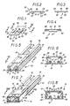
- FIGS. 5 to 8 it is a question of equipping a molding 10 intended for housing electrical conductors 11.
- the molding 10 is formed of a body 12 and a cover 13, which will be assumed, in the following, to be divided into sections.
- This molding 10 does not fall under the present invention, and being well known in itself, it will not be described in all its details here.
- its body 12 which is generally with a transverse U-shaped profile, comprises a sole 14 and two lateral branches 15 whose angled returns form, along their free edge, two lips 16 directed towards one another, and that, in a complementary manner, its cover 13 comprises, in a transverse profile in U able to cover the previous one, a central wall 17 and two side walls 18.
- the lips 16 of the body 12 are each stiffened, along their free edge, by a flange 19 directed towards the sole 14, this protrudes from the lateral branches 15, projecting therefrom. heels 20, and the side walls 18 of the cover 13 extend to these heels 20.
- This cover gasket 22 extends, in practice, transversely, from one of the lips 16 to the other of the body 12, and it comprises, at each of its ends, engagement means 23 suitable for enclosing such a lip 16.
- this cover gasket 22 forms in its central part a plate 24 of generally rectangular outline, the width of which corresponds to the spacing between the lips 16 of the body 12, and on the longitudinal sides of which extend, projecting , the corresponding engagement means 23.
- this plate 24 longitudinally with respect to the molding 10 is greater than its extension transversely with respect to the latter.
- the engagement means 23 are gripping means which comprise, in combination, on the one hand, two tongues 26, which, spaced apart from one of the other, are capable of engaging flat on any one of the upper or lower faces of a lip 16, at a point any of the latter, and, on the other hand, between these tongues 26, at least one return square 27, capable of coming to bear elastically on the other of the faces of this lip 16.
- the two tongues 26 extend in continuity with the central plate 24, each being respectively disposed at the ends of the corresponding longitudinal edge thereof, and they are intended to engage flat on the upper face of the lips 16 of the body 12.
- the return to square 27 stops at a distance from the free edge of the corresponding tabs 26.
- this embodiment comprises, projecting along its free edge, on the side of the tongues 26, a flange 29, suitable for enabling it to be hooked on the flange 19 of the lip 15 concerned.
- the square return 27 thus formed extends, longitudinally, over a length greater than that along which each of the corresponding tabs 26 individually extends, from one to the other of these.
- each of these tongues 26 has, longitudinally, projecting on its underside, and in continuity with the root 31 of the square return 27, a rib 32.
- the establishment of the cover gasket 22 according to the invention is done by simple snap-fastening.
- this cover gasket 22 encloses, elastically, between its tongues 26 and its square returns 27, the lips 16 of the body 12.
- the clip which thus constitutes the cover gasket 22 according to the invention advantageously ensures the retention of the wires, cables or electrical conductors 11, even before the installation, optionally section by section, of the cover 13.
Landscapes
- Engineering & Computer Science (AREA)
- Architecture (AREA)
- Civil Engineering (AREA)
- Structural Engineering (AREA)
- Installation Of Indoor Wiring (AREA)
- Insulating Bodies (AREA)
Applications Claiming Priority (2)
| Application Number | Priority Date | Filing Date | Title |
|---|---|---|---|
| FR8911267 | 1989-08-25 | ||
| FR8911267A FR2651387B1 (fr) | 1989-08-25 | 1989-08-25 | Joint de couvercle formant agrafe, pour moulure ou autre goulotte. |
Publications (2)
| Publication Number | Publication Date |
|---|---|
| EP0414616A1 true EP0414616A1 (de) | 1991-02-27 |
| EP0414616B1 EP0414616B1 (de) | 1993-11-03 |
Family
ID=9384925
Family Applications (1)
| Application Number | Title | Priority Date | Filing Date |
|---|---|---|---|
| EP19900402354 Expired - Lifetime EP0414616B1 (de) | 1989-08-25 | 1990-08-24 | Klammerartige Abdeckungsverbindung für eine Leiste oder Rinne |
Country Status (4)
| Country | Link |
|---|---|
| EP (1) | EP0414616B1 (de) |
| DE (1) | DE69004380T2 (de) |
| ES (1) | ES2047289T3 (de) |
| FR (1) | FR2651387B1 (de) |
Cited By (6)
| Publication number | Priority date | Publication date | Assignee | Title |
|---|---|---|---|---|
| EP0624940A1 (de) * | 1993-05-14 | 1994-11-17 | Legrand | Rinne mit einer Abdeckungsverbindung mit Verriegelungsvorrichtung, insbesondere für elektrische Geräte |
| GB2278739A (en) * | 1993-06-03 | 1994-12-07 | Warden Plastics | Cable trunking |
| EP0682394A1 (de) * | 1994-05-13 | 1995-11-15 | Bocchiotti Societa'per L'industria Elettrotecnica S.P.A. | Wand- oder Sockelleistenkanal für elektrische Kabel |
| EP0840416A3 (de) * | 1996-10-29 | 1999-08-04 | Electrix (Northern) Limited | Geschlossene Bauteil |
| FR2806848A1 (fr) * | 2000-03-24 | 2001-09-28 | Legrand Sa | Accessoire a rapporter sur un socle de goulotte de cheminement de conducteurs ou de cables electriques |
| US12300982B2 (en) * | 2020-09-09 | 2025-05-13 | Seong-Jun Kim | Cable mold |
Families Citing this family (3)
| Publication number | Priority date | Publication date | Assignee | Title |
|---|---|---|---|---|
| FR2799897B1 (fr) * | 1999-10-15 | 2006-08-04 | Legrand Sa | Accessoire a rapporter sur un socle de goulotte de cheminement de cables electriques |
| FR2799900B1 (fr) * | 1999-10-18 | 2002-01-04 | Legrand Sa | Agrafe de retenue pour goulotte, notamment pour appareillages electriques |
| ES1072782Y (es) | 2010-05-14 | 2010-12-28 | Unex Aparellaje Electrico Sl | Cubrejuntas para bandejas con tapa portadoras de conductores electricos |
Citations (3)
| Publication number | Priority date | Publication date | Assignee | Title |
|---|---|---|---|---|
| FR2132807A1 (de) * | 1971-04-10 | 1972-11-24 | Rehau Plastiks | |
| US4077434A (en) * | 1976-05-27 | 1978-03-07 | Federal Cartridge Corporation | Sealed lay-in conduit duct |
| FR2473226A1 (fr) * | 1980-01-03 | 1981-07-10 | Villi Canalplast | Gaine porte-cables, notamment pour constructions privees et industrielles prefabriquees |
-
1989
- 1989-08-25 FR FR8911267A patent/FR2651387B1/fr not_active Expired - Fee Related
-
1990
- 1990-08-24 ES ES90402354T patent/ES2047289T3/es not_active Expired - Lifetime
- 1990-08-24 EP EP19900402354 patent/EP0414616B1/de not_active Expired - Lifetime
- 1990-08-24 DE DE1990604380 patent/DE69004380T2/de not_active Expired - Fee Related
Patent Citations (3)
| Publication number | Priority date | Publication date | Assignee | Title |
|---|---|---|---|---|
| FR2132807A1 (de) * | 1971-04-10 | 1972-11-24 | Rehau Plastiks | |
| US4077434A (en) * | 1976-05-27 | 1978-03-07 | Federal Cartridge Corporation | Sealed lay-in conduit duct |
| FR2473226A1 (fr) * | 1980-01-03 | 1981-07-10 | Villi Canalplast | Gaine porte-cables, notamment pour constructions privees et industrielles prefabriquees |
Cited By (10)
| Publication number | Priority date | Publication date | Assignee | Title |
|---|---|---|---|---|
| EP0624940A1 (de) * | 1993-05-14 | 1994-11-17 | Legrand | Rinne mit einer Abdeckungsverbindung mit Verriegelungsvorrichtung, insbesondere für elektrische Geräte |
| FR2705505A1 (fr) * | 1993-05-14 | 1994-11-25 | Legrand Sa | Goulotte à joint de couvercle équipé d'un verrou, notamment pour appareillages électriques. |
| US5569884A (en) * | 1993-05-14 | 1996-10-29 | Legrand | Trunking with cover jointing members, suitable for electrical apparatus |
| GB2278739A (en) * | 1993-06-03 | 1994-12-07 | Warden Plastics | Cable trunking |
| EP0682394A1 (de) * | 1994-05-13 | 1995-11-15 | Bocchiotti Societa'per L'industria Elettrotecnica S.P.A. | Wand- oder Sockelleistenkanal für elektrische Kabel |
| EP0840416A3 (de) * | 1996-10-29 | 1999-08-04 | Electrix (Northern) Limited | Geschlossene Bauteil |
| FR2806848A1 (fr) * | 2000-03-24 | 2001-09-28 | Legrand Sa | Accessoire a rapporter sur un socle de goulotte de cheminement de conducteurs ou de cables electriques |
| EP1139535A1 (de) * | 2000-03-24 | 2001-10-04 | Legrand | Zubehör für elektrischen Verkabelungskanalsockel |
| US6479747B2 (en) | 2000-03-24 | 2002-11-12 | Legrand | Accessory for fitting to the base section of trunking for routing electrical cables or conductors |
| US12300982B2 (en) * | 2020-09-09 | 2025-05-13 | Seong-Jun Kim | Cable mold |
Also Published As
| Publication number | Publication date |
|---|---|
| FR2651387A1 (fr) | 1991-03-01 |
| FR2651387B1 (fr) | 1992-04-17 |
| ES2047289T3 (es) | 1994-02-16 |
| EP0414616B1 (de) | 1993-11-03 |
| DE69004380T2 (de) | 1994-02-24 |
| DE69004380D1 (de) | 1993-12-09 |
Similar Documents
| Publication | Publication Date | Title |
|---|---|---|
| EP1133819B1 (de) | Gerätegehäuse zum auf einen kabelkanalseite insbesondere für elektrisches gerät einbringen | |
| EP0414616B1 (de) | Klammerartige Abdeckungsverbindung für eine Leiste oder Rinne | |
| EP1094581B1 (de) | Durchführungszubehör für Kabelkanal | |
| EP0813663B1 (de) | Eckverbindungsvorrichtung für eine rinnenförmige leitung und eine abdeckung wie z.b. eine profilleiste, eine sockelleiste oder eine rinne, insbesondere für ein elektrisches bauteil | |
| FR2758016A1 (fr) | Procede et dispositif pour affermir le maintien sur une goulotte d'un quelconque accessoire a rapporter par emboitement sur le socle de celle-ci | |
| EP2079138B1 (de) | Zubehör für elektrischen Kabelkanal, Elektroeinheit, die ein Elektrogerät und ein solches Zubehörteil umfasst, sowie Elektroeinheit, die einen elektrischen Kabelkanal und ein solches Zubehörteil umfasst | |
| EP0351293A1 (de) | Blockierbefestigung für einen Modulstapel auf einer Aufnahmeschiene | |
| EP0838885B1 (de) | Halteklammer für Kabelrinnen und zugehörige Kabelrinne | |
| EP0267079B1 (de) | Abzweigungszubehör für Verkabelungsrohr | |
| FR2768268A1 (fr) | Agrafe de retenue ,notamment pour goulotte destinee a des appareillages electriques | |
| EP2079139B1 (de) | Electric raceway in which the base comprises means for braking electrical switchgears or accessories connected to the base, and electric assembly comprising such an electric raceway and dedicated electrical switchgear | |
| EP0964494B1 (de) | Abzweigungszubehör für Elektroinstallation sowie Elektroinstallation | |
| EP1211773B1 (de) | Träger für ein Gerät, inbesondere für ein elektrisches Gerät, zur Befestigung auf einem Kabelkanalkörper | |
| EP0887903B1 (de) | Sockel für Kabelkanal mit einem V-förmigen Querschnitt, insbesondere Eckkanal oder Unterputzkanal | |
| EP0999627A1 (de) | Sockel für Kabelkanal mit vorgeformten Bohrungen und Verfahren ihrer Herstellung | |
| EP0657657B1 (de) | Element zur Montage von Zubehör an einer perforierten Mauer | |
| EP0986157A1 (de) | Elektrisches Gerät mit einem länglichen Hohlkörper zum behalten von elektrischen Elementen | |
| EP0713040A1 (de) | Schelle mit integriertem Dübel zur Wandbefestigung eines Rohres | |
| FR2779877A1 (fr) | Boite d'encastrement a corps de boite et pied prolongeant lateralement le corps de boite, notamment pour appareil electrique | |
| FR2588439A1 (fr) | Boitier de support pour appareillage electrique, notamment pour appareillage electrique du type dit a encastrer | |
| FR2732089A1 (fr) | Accessoire pour goulotte, notamment pour conducteurs electriques | |
| EP1617535A1 (de) | Flacheckverbindungs- oder Abzweigungseinrichtung passend für verschiedene Rinnenecken | |
| FR2756902A1 (fr) | Procede et accessoire pour la fixation d'une goulotte a un support | |
| EP1085143A1 (de) | Abnehmbare Sockelleiste zum Durchführen von elektrischen Drähten oder Kabeln | |
| FR2517255A1 (fr) | Monture de timbre |
Legal Events
| Date | Code | Title | Description |
|---|---|---|---|
| PUAI | Public reference made under article 153(3) epc to a published international application that has entered the european phase |
Free format text: ORIGINAL CODE: 0009012 |
|
| AK | Designated contracting states |
Kind code of ref document: A1 Designated state(s): DE ES GB IT |
|
| 17P | Request for examination filed |
Effective date: 19910325 |
|
| 17Q | First examination report despatched |
Effective date: 19930218 |
|
| GRAA | (expected) grant |
Free format text: ORIGINAL CODE: 0009210 |
|
| AK | Designated contracting states |
Kind code of ref document: B1 Designated state(s): DE ES GB IT |
|
| REF | Corresponds to: |
Ref document number: 69004380 Country of ref document: DE Date of ref document: 19931209 |
|
| GBT | Gb: translation of ep patent filed (gb section 77(6)(a)/1977) |
Effective date: 19931111 |
|
| ITF | It: translation for a ep patent filed | ||
| REG | Reference to a national code |
Ref country code: ES Ref legal event code: FG2A Ref document number: 2047289 Country of ref document: ES Kind code of ref document: T3 |
|
| PLBE | No opposition filed within time limit |
Free format text: ORIGINAL CODE: 0009261 |
|
| STAA | Information on the status of an ep patent application or granted ep patent |
Free format text: STATUS: NO OPPOSITION FILED WITHIN TIME LIMIT |
|
| 26N | No opposition filed | ||
| REG | Reference to a national code |
Ref country code: GB Ref legal event code: IF02 |
|
| PGFP | Annual fee paid to national office [announced via postgrant information from national office to epo] |
Ref country code: GB Payment date: 20040803 Year of fee payment: 15 |
|
| PGFP | Annual fee paid to national office [announced via postgrant information from national office to epo] |
Ref country code: DE Payment date: 20040806 Year of fee payment: 15 |
|
| PGFP | Annual fee paid to national office [announced via postgrant information from national office to epo] |
Ref country code: ES Payment date: 20040816 Year of fee payment: 15 |
|
| PG25 | Lapsed in a contracting state [announced via postgrant information from national office to epo] |
Ref country code: IT Free format text: LAPSE BECAUSE OF NON-PAYMENT OF DUE FEES;WARNING: LAPSES OF ITALIAN PATENTS WITH EFFECTIVE DATE BEFORE 2007 MAY HAVE OCCURRED AT ANY TIME BEFORE 2007. THE CORRECT EFFECTIVE DATE MAY BE DIFFERENT FROM THE ONE RECORDED. Effective date: 20050824 Ref country code: GB Free format text: LAPSE BECAUSE OF NON-PAYMENT OF DUE FEES Effective date: 20050824 |
|
| PG25 | Lapsed in a contracting state [announced via postgrant information from national office to epo] |
Ref country code: ES Free format text: LAPSE BECAUSE OF NON-PAYMENT OF DUE FEES Effective date: 20050825 |
|
| PG25 | Lapsed in a contracting state [announced via postgrant information from national office to epo] |
Ref country code: DE Free format text: LAPSE BECAUSE OF NON-PAYMENT OF DUE FEES Effective date: 20060301 |
|
| GBPC | Gb: european patent ceased through non-payment of renewal fee |
Effective date: 20050824 |
|
| REG | Reference to a national code |
Ref country code: ES Ref legal event code: FD2A Effective date: 20050825 |