EP0414646A2 - Kranausleger - Google Patents
Kranausleger Download PDFInfo
- Publication number
- EP0414646A2 EP0414646A2 EP90830275A EP90830275A EP0414646A2 EP 0414646 A2 EP0414646 A2 EP 0414646A2 EP 90830275 A EP90830275 A EP 90830275A EP 90830275 A EP90830275 A EP 90830275A EP 0414646 A2 EP0414646 A2 EP 0414646A2
- Authority
- EP
- European Patent Office
- Prior art keywords
- crane
- jib
- cable
- boom
- pulley
- Prior art date
- Legal status (The legal status is an assumption and is not a legal conclusion. Google has not performed a legal analysis and makes no representation as to the accuracy of the status listed.)
- Withdrawn
Links
- 230000007246 mechanism Effects 0.000 description 1
Images

Classifications
-
- B—PERFORMING OPERATIONS; TRANSPORTING
- B66—HOISTING; LIFTING; HAULING
- B66C—CRANES; LOAD-ENGAGING ELEMENTS OR DEVICES FOR CRANES, CAPSTANS, WINCHES, OR TACKLES
- B66C11/00—Trolleys or crabs, e.g. operating above runways
- B66C11/16—Rope, cable, or chain drives for trolleys; Combinations of such drives with hoisting gear
- B66C11/18—Rope, cable, or chain drives for trolleys; Combinations of such drives with hoisting gear comprising endless ropes or cables
-
- B—PERFORMING OPERATIONS; TRANSPORTING
- B66—HOISTING; LIFTING; HAULING
- B66C—CRANES; LOAD-ENGAGING ELEMENTS OR DEVICES FOR CRANES, CAPSTANS, WINCHES, OR TACKLES
- B66C23/00—Cranes comprising essentially a beam, boom, or triangular structure acting as a cantilever and mounted for translatory of swinging movements in vertical or horizontal planes or a combination of such movements, e.g. jib-cranes, derricks, tower cranes
- B66C23/62—Constructional features or details
- B66C23/64—Jibs
- B66C23/68—Jibs foldable or otherwise adjustable in configuration
-
- B—PERFORMING OPERATIONS; TRANSPORTING
- B66—HOISTING; LIFTING; HAULING
- B66C—CRANES; LOAD-ENGAGING ELEMENTS OR DEVICES FOR CRANES, CAPSTANS, WINCHES, OR TACKLES
- B66C7/00—Runways, tracks or trackways for trolleys or cranes
- B66C7/16—Devices specially adapted for limiting trolley or crane travel; Arrangements of buffer-stops
Definitions
- the present invention refers to crane jibs and particularly to those which consist of two parts hinged together, the one which is outermost is foldable on the one which is connected to the support tower.
- crane jibs of the aforementioned type including lever systems, pulleys and cables actuated by a motor, that is to say, hydraulic groups acting on a set of connecting rods, allow the folding of said jibs, are known technically.
- the mechanisms described above allow the crane boom to assume either an extended traditional conformation, in which the two parts are axially aligned, or a folded conformation, of minimal bulk, allowing the lifting of the crane boom in tight spaces.
- the above characteristics allow the crane to be mounted even in tight spaces, on the other hand they do not favor its use when the boom is folded, thus limiting its use.
- the object of the present invention is to produce a crane boom of the type specified above, not having the limitations described above.
- the present invention relates to a crane jib essentially consisting of two parts articulated together, the outermost of which is foldable on that which is connected to the support tower, and of a cable sliding between a winch and a series of pulleys which, when the crane boom is extended, has an upper branch and a lower branch, the latter connected and driving a carriage;
- said crane boom being characterized in that it comprises: - A first pulley carried by the part of the jib connected to the support tower and placed at the end assembled with the folding jib part, so as to correspond to the lower branch of the cable; - A second pulley carried by the folding part of the crane boom and placed very next to said first pulley; - A third pulley also carried by the foldable part of the crane jib and placed at the end connected to the part of the jib attached to the tower, so as to correspond to the upper branch of the cable;
- Said pulleys being able to move with said cable so as to allow its sliding even when the crane boom is folded;
- said crane jib being further characterized by the fact that it comprises an end-of-travel stop for said carriage, consisting of a mark mounted freely on a pivot on the part of the jib connected to the support tower, which is placed so as to correspond to the end of the articulated part on the folding jib part.
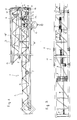
- 1 indicates the articulated boom as a whole. This arrow is notoriously connected to a support tower (not shown) and is composed of two lattice parts 2 and 3 which can be produced in any geometric configuration and which, in the illustrated embodiment, are provided with a triangular base.
- Said two parts of the trellis are interconnected in axial alignment by means of a hinge 4 which allows the tilting of the trellis 3 on trellis 2.
- said arrow 1 comprises a winch 7 driven by an electric motor (not illustrated) and by a series of pulleys in which slide two ends of cable 8 and 9.
- the end 9 is, at one end, wound on said winch 7 while the other end is connected to one side of the carriage 10, passing through a pulley 11, the end 8 in turn, has one end wound on said winch 7 while the other end is connected to the other side of the carriage 10 through the pulleys 12, 13 and 14 which have the function of adjusting the tension of the cable, and by the end pulley 15.
- arrow 1 with extended conformation, is provided with a cable which follows a closed ring trajectory having an upper branch "A” and a lower branch "B".
- the carriage 10, connected to the cable ends 8 and 9 is able to slide, driven by the latter on tracks obtained in the lattice structure of the arrow 1.
- the jib 1 has three other pulleys, the first of which, designated by 16, is carried by the part of the trellis 2 connected to the support tower and is placed at the end connected to the trellis. 3 foldable, so as to correspond to the lower branch "B" of the cable; the second, designated by 17, is carried by the folding part of the trellis 3 and is placed right next to the first pulley 16; the third, designated by 18, is also carried by the foldable part of the trellis 3 and is placed at the end connected to the part of the trellis 2, so as to correspond to the upper branch "A" of the cable and in alignment with the pulley system 13 and 14.
- the aforesaid carriage 10 when the arrow is folded, requires an end-of-travel mark 19 consisting of a plate 20, provided with a counterweight 21, mounted freely on the pivot on the trellis structure 2 and placed as shown in Figure 2.
- Said limit switch 19 has a pivot 22 turned outwards so as to be contacted by the trellis structure 3, as soon as the extended conformation of the crane boom is restored, in order to push the plate 20 into the position illustrated in FIG. 1, by releasing the sliding track of said carriage 10.
- the above crane boom 1 finally has a device for adjusting the cable tension constituted by an elastic means 23 inserted coaxially on a pivot 24 with nut 25 which acts on said pulley 13 to adjust its position in relation to a reference 26.
Landscapes
- Engineering & Computer Science (AREA)
- Mechanical Engineering (AREA)
- Jib Cranes (AREA)
Applications Claiming Priority (1)
| Application Number | Priority Date | Filing Date | Title |
|---|---|---|---|
| IT8967491A IT1234395B (it) | 1989-06-16 | 1989-06-16 | Braccio di gru |
Publications (2)
| Publication Number | Publication Date |
|---|---|
| EP0414646A2 true EP0414646A2 (de) | 1991-02-27 |
| EP0414646A3 EP0414646A3 (en) | 1992-06-03 |
Family
ID=11302867
Family Applications (1)
| Application Number | Title | Priority Date | Filing Date |
|---|---|---|---|
| EP19900830275 Withdrawn EP0414646A3 (en) | 1989-06-16 | 1990-06-15 | Crane jib |
Country Status (2)
| Country | Link |
|---|---|
| EP (1) | EP0414646A3 (de) |
| IT (1) | IT1234395B (de) |
Cited By (4)
| Publication number | Priority date | Publication date | Assignee | Title |
|---|---|---|---|---|
| US6276541B1 (en) * | 1999-02-26 | 2001-08-21 | Potain | Device for simultaneously unfolding or folding crane jib tip elements |
| FR2813298A1 (fr) * | 2000-08-30 | 2002-03-01 | Potain Sa | Circuit de cable de distribution pour grue a tour |
| CN102417144A (zh) * | 2011-08-12 | 2012-04-18 | 中联重科股份有限公司 | 折叠臂架结构和工程机械 |
| EP3225582A1 (de) * | 2016-04-01 | 2017-10-04 | Manitowoc Crane Group France | Zusammenklappbare konstruktion zum zusammenbau eines turmkrans |
Family Cites Families (4)
| Publication number | Priority date | Publication date | Assignee | Title |
|---|---|---|---|---|
| DE1090833B (de) * | 1956-04-27 | 1960-10-13 | Otto Kaiser Kommandit Ges Masc | Turmdrehkran |
| DE1958490A1 (de) * | 1969-11-21 | 1971-06-03 | W & M Automation Karl Mueller | Kettentrieb fuer den Laufwagen von Ladeportalen |
| IT1182698B (it) * | 1985-11-22 | 1987-10-05 | Andrea Ferreri | Braccio per gru |
| GB8720596D0 (en) * | 1987-09-02 | 1987-10-07 | British Petroleum Co Plc | Folding boom |
-
1989
- 1989-06-16 IT IT8967491A patent/IT1234395B/it active
-
1990
- 1990-06-15 EP EP19900830275 patent/EP0414646A3/fr not_active Withdrawn
Cited By (8)
| Publication number | Priority date | Publication date | Assignee | Title |
|---|---|---|---|---|
| US6276541B1 (en) * | 1999-02-26 | 2001-08-21 | Potain | Device for simultaneously unfolding or folding crane jib tip elements |
| FR2813298A1 (fr) * | 2000-08-30 | 2002-03-01 | Potain Sa | Circuit de cable de distribution pour grue a tour |
| EP1184328A1 (de) * | 2000-08-30 | 2002-03-06 | Potain | Seilanordnung für einen Turmkran |
| RU2271331C2 (ru) * | 2000-08-30 | 2006-03-10 | Потэн С.А. | Схема прокладки каната грузораспределения для башенных кранов |
| CN102417144A (zh) * | 2011-08-12 | 2012-04-18 | 中联重科股份有限公司 | 折叠臂架结构和工程机械 |
| CN102417144B (zh) * | 2011-08-12 | 2013-01-16 | 中联重科股份有限公司 | 折叠臂架结构和工程机械 |
| EP3225582A1 (de) * | 2016-04-01 | 2017-10-04 | Manitowoc Crane Group France | Zusammenklappbare konstruktion zum zusammenbau eines turmkrans |
| FR3049593A1 (fr) * | 2016-04-01 | 2017-10-06 | Manitowoc Crane Group France | Structure pliable pour composer une grue a tour |
Also Published As
| Publication number | Publication date |
|---|---|
| IT1234395B (it) | 1992-05-18 |
| IT8967491A0 (it) | 1989-06-16 |
| EP0414646A3 (en) | 1992-06-03 |
Similar Documents
| Publication | Publication Date | Title |
|---|---|---|
| FR2548639A1 (fr) | Mecanisme d'equilibrage pour la rampe d'une passerelle de dock | |
| EP1184328B1 (de) | Seilanordnung für einen Turmkran | |
| FR2492744A1 (fr) | Dispositif a chaines de protection pour roues | |
| EP0846650A1 (de) | Verfahren und Vorrichtung zum Montieren der Seilzüge der Ausleger von Turmkränen | |
| EP0414646A2 (de) | Kranausleger | |
| EP0538161B1 (de) | Entastvorrichtung für Bäume | |
| EP0500499A1 (de) | Store | |
| FR2979939A3 (fr) | Contrevent pliant | |
| EP0473518B1 (de) | Selbstaufstellender Kran mit seitlich klappbarem Ausleger | |
| FR2731999A1 (fr) | Grue a montage automatise avec fleche repliable lateralement | |
| EP4048621A1 (de) | Kran mit teleskopausleger und verfahren zur handhabung einer last mit einem solchen kran | |
| FR2679544A1 (fr) | Appareilage autonome permettant d'extraire et deplacer des elements encastres dans le sol, tels que plaques d'egouts, grilles. | |
| CH367957A (fr) | Grue à mât relevable | |
| EP1790211B1 (de) | Vorschneidemaschine mit integrierten Ausweichmitteln für Pfähle oder ähnliches | |
| FR2584451A1 (de) | ||
| FR2636616A1 (fr) | Grue repliable a fleche en deux ou trois elements articules les uns aux autres | |
| EP0331856B1 (de) | Zusammenlegbarer Kran mit automatischer und schneller Aufrichtung | |
| EP0204051A1 (de) | Segelreffeinrichtung und Baum mit dieser Einrichtung | |
| BE664573A (de) | ||
| EP1116842B1 (de) | Ausgleichsvorrichtung für eine Hubtür | |
| FR2594427A1 (fr) | Bras pour grue | |
| BE1004283A3 (fr) | Echenilloir. | |
| FR2628666A1 (fr) | Machine a sectionner les cables electriques munie d'un outil de coupe rotatif | |
| EP0145627A1 (de) | Lastenaufzug mit Doppelrichtungsantrieb für die bewegliche Ausstattung | |
| FR2673926A1 (fr) | Plate-forme elevatrice a ciseaux. |
Legal Events
| Date | Code | Title | Description |
|---|---|---|---|
| PUAI | Public reference made under article 153(3) epc to a published international application that has entered the european phase |
Free format text: ORIGINAL CODE: 0009012 |
|
| AK | Designated contracting states |
Kind code of ref document: A2 Designated state(s): DE ES FR |
|
| PUAL | Search report despatched |
Free format text: ORIGINAL CODE: 0009013 |
|
| AK | Designated contracting states |
Kind code of ref document: A3 Designated state(s): DE ES FR |
|
| 17P | Request for examination filed |
Effective date: 19921203 |
|
| 17Q | First examination report despatched |
Effective date: 19950327 |
|
| STAA | Information on the status of an ep patent application or granted ep patent |
Free format text: STATUS: THE APPLICATION IS DEEMED TO BE WITHDRAWN |
|
| 18D | Application deemed to be withdrawn |
Effective date: 19951031 |