EP0414955A1 - Pompe à haute pression pour des disposifs à nettoyer ou appareils du même type - Google Patents
Pompe à haute pression pour des disposifs à nettoyer ou appareils du même type Download PDFInfo
- Publication number
- EP0414955A1 EP0414955A1 EP89116198A EP89116198A EP0414955A1 EP 0414955 A1 EP0414955 A1 EP 0414955A1 EP 89116198 A EP89116198 A EP 89116198A EP 89116198 A EP89116198 A EP 89116198A EP 0414955 A1 EP0414955 A1 EP 0414955A1
- Authority
- EP
- European Patent Office
- Prior art keywords
- piston
- head
- pump according
- drive
- tie rod
- Prior art date
- Legal status (The legal status is an assumption and is not a legal conclusion. Google has not performed a legal analysis and makes no representation as to the accuracy of the status listed.)
- Withdrawn
Links
- 238000004140 cleaning Methods 0.000 claims abstract description 3
- 239000000919 ceramic Substances 0.000 claims description 20
- 229910000831 Steel Inorganic materials 0.000 claims description 2
- 239000010959 steel Substances 0.000 claims description 2
- 229910010293 ceramic material Inorganic materials 0.000 abstract description 3
- 239000002184 metal Substances 0.000 description 6
- 238000005086 pumping Methods 0.000 description 3
- 238000004519 manufacturing process Methods 0.000 description 2
- 239000007769 metal material Substances 0.000 description 2
- 238000007789 sealing Methods 0.000 description 2
- 238000003466 welding Methods 0.000 description 2
- 238000004026 adhesive bonding Methods 0.000 description 1
- 230000001771 impaired effect Effects 0.000 description 1
- 238000000034 method Methods 0.000 description 1
- 230000004048 modification Effects 0.000 description 1
- 238000012986 modification Methods 0.000 description 1
- 238000003825 pressing Methods 0.000 description 1
- 238000007493 shaping process Methods 0.000 description 1
- 238000005476 soldering Methods 0.000 description 1
- 239000000126 substance Substances 0.000 description 1
Images

Classifications
-
- F—MECHANICAL ENGINEERING; LIGHTING; HEATING; WEAPONS; BLASTING
- F04—POSITIVE - DISPLACEMENT MACHINES FOR LIQUIDS; PUMPS FOR LIQUIDS OR ELASTIC FLUIDS
- F04B—POSITIVE-DISPLACEMENT MACHINES FOR LIQUIDS; PUMPS
- F04B53/00—Component parts, details or accessories not provided for in, or of interest apart from, groups F04B1/00 - F04B23/00 or F04B39/00 - F04B47/00
- F04B53/14—Pistons, piston-rods or piston-rod connections
-
- F—MECHANICAL ENGINEERING; LIGHTING; HEATING; WEAPONS; BLASTING
- F04—POSITIVE - DISPLACEMENT MACHINES FOR LIQUIDS; PUMPS FOR LIQUIDS OR ELASTIC FLUIDS
- F04B—POSITIVE-DISPLACEMENT MACHINES FOR LIQUIDS; PUMPS
- F04B1/00—Multi-cylinder machines or pumps characterised by number or arrangement of cylinders
- F04B1/12—Multi-cylinder machines or pumps characterised by number or arrangement of cylinders having cylinder axes coaxial with, or parallel or inclined to, main shaft axis
- F04B1/122—Details or component parts, e.g. valves, sealings or lubrication means
- F04B1/124—Pistons
-
- F—MECHANICAL ENGINEERING; LIGHTING; HEATING; WEAPONS; BLASTING
- F05—INDEXING SCHEMES RELATING TO ENGINES OR PUMPS IN VARIOUS SUBCLASSES OF CLASSES F01-F04
- F05C—INDEXING SCHEME RELATING TO MATERIALS, MATERIAL PROPERTIES OR MATERIAL CHARACTERISTICS FOR MACHINES, ENGINES OR PUMPS OTHER THAN NON-POSITIVE-DISPLACEMENT MACHINES OR ENGINES
- F05C2203/00—Non-metallic inorganic materials
- F05C2203/08—Ceramics; Oxides
Definitions
- the invention relates to a high-pressure piston pump for cleaning devices or the like having a drive which periodically displaces the pistons and which essentially consist of ceramic and has a head which is operatively connected to the drive.
- a high pressure pump is known for example from DE-OS 37 02 446.
- the piston is thus formed in the form of a sleeve, the hollow core or the longitudinal bore being produced during the shaping of the piston, that is to say the expression “longitudinal bore” does not necessarily mean that the hollow interior of the piston is actually produced by introducing a bore. This expression could also be replaced by "longitudinal channel” or a similar expression.
- the sleeve-shaped ceramic piston is penetrated by a tie rod which is supported on the outside of the piston on the side facing away from the drive and is connected to the head on the drive side in such a way that the head is clamped against the end face of the piston.
- a tie rod which is supported on the outside of the piston on the side facing away from the drive and is connected to the head on the drive side in such a way that the head is clamped against the end face of the piston.
- tie rod is sealed against the inner wall of the longitudinal bore, so that the interior of the pump chamber is thereby sealed from the drive side.
- the tie rod can be supported on the pump chamber end face of the piston via a support element which has a larger radius than the longitudinal bore in the piston.
- This support element is preferably a disk.
- the support element can be formed in one piece with the tie rod.
- the head can be screwed onto the drive end of the tie rod, in another embodiment the tie rod and head are made of plastic and are welded or glued to one another.
- connection is also possible, for example the head and tie rod can be riveted or soldered to one another.
- the head tensions a spring support plate against the drive end face of the piston or if the head itself carries a spring support plate.
- a spring surrounding the piston and pressing the piston against the swash plate of a swash plate drive can be supported on this.
- the head is designed as a metallic contact element on a swashplate drive; in a modified embodiment, the head can also carry a ball-bearing sliding block which rests on a swashplate drive.
- the head is articulated to the connecting rod of a crank mechanism.
- the piston is sealed on the outside in a conventional manner by a high-pressure seal and a low-pressure seal. In some cases there are difficulties in sealing against the outer jacket of the ceramic piston due to the ceramic roughness. It can then be provided that the piston has an outer jacket made of steel at its drive-side end at which it is sealed, for example in the form of a pressed-on sleeve or in the form of a piston region which adjoins the ceramic piston region.
- FIG. 1 only one pump chamber with a piston is shown of a high-pressure piston pump of conventional design, which has, for example, three pumping chambers, into each of which a piston is immersed, and the drive means for the piston are essentially omitted.
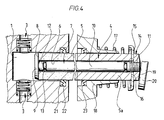
- a piston 4 is immersed in a cylindrical pump chamber 1 with an inlet valve 2 and an outlet valve 3.
- This piston consists of a circular cylindrical ceramic sleeve 5 with a central through opening or through hole 6, in which a tie rod 7 is located.
- This comprises a washer 9, which is supported on the end face 8 of the ceramic sleeve on the pump chamber side and is integrally connected to a pull rod 10 passing through the through opening 6, on the end of which opposite the washer 9 there is an external thread 11.
- ring seals 13 are inserted in two circumferential grooves, which seal the inner wall of the through opening 6 with respect to the tie rod 10.
- a contact head 14 is screwed onto the external thread 11 of the pull rod 10 and clamps a spring plate 15 against the end face 16 of the ceramic sleeve 5 facing away from the pumping chamber.
- the spring plate 15 protrudes radially beyond the ceramic sleeve 5, on which a coil spring 17, which concentrically surrounds the piston, is supported, the other end of which is supported on a pump-fixed guide 18 surrounding the piston.
- the coil spring 17 applies a force to the piston, which pulls it out of the pumping chamber 1, so that the bearing head 14 with an inclined bearing surface 19 is pressed elastically against a swash plate 20 of a drive (not shown).
- disc 9, tie rod 10 and contact head 14 consist of a metal, at least the contact head 14 being hardened.
- the dimensions can be chosen so that the piston has a diameter of 20 mm, for example, the wall thickness of the ceramic sleeve 5 being 7 mm, so that the inside diameter of the through opening 6 is 6 mm.
- the ceramic sleeve 5 extends over the entire length of the piston.
- a small area of this ceramic sleeve 5 is replaced by a further sleeve 5a made of a metal, the low-pressure seal 23 abutting in this area.
- a metal sleeve could also be pressed onto a partial area of the piston 5, this metal sleeve also forming a sealing surface with respect to the low-pressure seal 23.
- the contact head 14 carries a ball 24 on which a sliding block 25 is mounted, which in turn is supported on the swash plate 20.
- the result is a ball-and-socket mounting of the sliding block 25 on the contact head 14.
- the bearing head 14 is provided with a fork-like bearing 26, on which the connecting rod 28 of a crank mechanism, not otherwise shown, is mounted by means of a piston pin 27.
- a swash plate drive is not used, but a crank drive.
- the spring plate 15 and the contact head 14 are separate components, it would also be possible to form the contact head and the spring plate in one piece.
- the pull rod can be made of plastic at lower loads, the same applies to the contact head. These parts can be connected to one another, for example, by welding or gluing.
- connection techniques can also be used, for example welding, soldering or riveting.
- the contact head 14 is not fixed directly on the adjoining area of the ceramic piston, but is supported on the opposite side of the piston via a pull rod which penetrates the entire sleeve-shaped piston.
Landscapes
- Engineering & Computer Science (AREA)
- Mechanical Engineering (AREA)
- General Engineering & Computer Science (AREA)
- Details Of Reciprocating Pumps (AREA)
Applications Claiming Priority (1)
| Application Number | Priority Date | Filing Date | Title |
|---|---|---|---|
| DE8910468U DE8910468U1 (de) | 1989-09-01 | 1989-09-01 | Hochdruckkolbenpumpe für Reinigungsgeräte od.dgl. |
Publications (1)
| Publication Number | Publication Date |
|---|---|
| EP0414955A1 true EP0414955A1 (fr) | 1991-03-06 |
Family
ID=6842488
Family Applications (1)
| Application Number | Title | Priority Date | Filing Date |
|---|---|---|---|
| EP89116198A Withdrawn EP0414955A1 (fr) | 1989-09-01 | 1989-09-01 | Pompe à haute pression pour des disposifs à nettoyer ou appareils du même type |
Country Status (2)
| Country | Link |
|---|---|
| EP (1) | EP0414955A1 (fr) |
| DE (1) | DE8910468U1 (fr) |
Cited By (23)
| Publication number | Priority date | Publication date | Assignee | Title |
|---|---|---|---|---|
| US10774828B1 (en) | 2020-01-17 | 2020-09-15 | Vulcan Industrial Holdings LLC | Composite valve seat system and method |
| US11242849B1 (en) | 2020-07-15 | 2022-02-08 | Vulcan Industrial Holdings, LLC | Dual use valve member for a valve assembly |
| US11353117B1 (en) | 2020-01-17 | 2022-06-07 | Vulcan Industrial Holdings, LLC | Valve seat insert system and method |
| US11384756B1 (en) * | 2020-08-19 | 2022-07-12 | Vulcan Industrial Holdings, LLC | Composite valve seat system and method |
| US11391374B1 (en) | 2021-01-14 | 2022-07-19 | Vulcan Industrial Holdings, LLC | Dual ring stuffing box |
| US11421680B1 (en) | 2020-06-30 | 2022-08-23 | Vulcan Industrial Holdings, LLC | Packing bore wear sleeve retainer system |
| US11421679B1 (en) | 2020-06-30 | 2022-08-23 | Vulcan Industrial Holdings, LLC | Packing assembly with threaded sleeve for interaction with an installation tool |
| US11434900B1 (en) | 2022-04-25 | 2022-09-06 | Vulcan Industrial Holdings, LLC | Spring controlling valve |
| USD980876S1 (en) | 2020-08-21 | 2023-03-14 | Vulcan Industrial Holdings, LLC | Fluid end for a pumping system |
| USD986928S1 (en) | 2020-08-21 | 2023-05-23 | Vulcan Industrial Holdings, LLC | Fluid end for a pumping system |
| USD997992S1 (en) | 2020-08-21 | 2023-09-05 | Vulcan Industrial Holdings, LLC | Fluid end for a pumping system |
| US11920684B1 (en) | 2022-05-17 | 2024-03-05 | Vulcan Industrial Holdings, LLC | Mechanically or hybrid mounted valve seat |
| US12049889B2 (en) | 2020-06-30 | 2024-07-30 | Vulcan Industrial Holdings, LLC | Packing bore wear sleeve retainer system |
| US12055221B2 (en) | 2021-01-14 | 2024-08-06 | Vulcan Industrial Holdings, LLC | Dual ring stuffing box |
| US12140240B1 (en) | 2022-01-19 | 2024-11-12 | Vulcan Industrial Holdings, LLC | Gradient material structures and methods of forming the same |
| USD1061623S1 (en) | 2022-08-03 | 2025-02-11 | Vulcan Industrial Holdings, LLC | Fluid end for a pumping system |
| US12292121B2 (en) | 2023-08-10 | 2025-05-06 | Vulcan Industrial Holdings, LLC | Valve member including cavity, and related assemblies, systems, and methods |
| US12292120B1 (en) | 2021-02-23 | 2025-05-06 | Vulcan Industrial Holdings, LLC | System and method for valve assembly |
| US12297922B1 (en) | 2022-03-04 | 2025-05-13 | Vulcan Industrial Holdings, LLC | Valve seat with embedded structure and related methods |
| US12345332B2 (en) | 2021-08-18 | 2025-07-01 | Vulcan Industrial Holdings, LLC | Self-locking plug |
| US12366245B1 (en) | 2020-08-27 | 2025-07-22 | Vulcan Industrial Holdings, LLC | Connecting rod assembly for reciprocating pump |
| US12510164B1 (en) | 2021-08-18 | 2025-12-30 | Vulcan Industrial Holdings, LLC | Sleeved fluid end |
| USD1113987S1 (en) | 2022-05-20 | 2026-02-17 | Vulcan Industrial Holdings, LLC | Header ring for a pumping system |
Families Citing this family (4)
| Publication number | Priority date | Publication date | Assignee | Title |
|---|---|---|---|---|
| DE4108105C2 (de) * | 1991-03-13 | 1994-10-20 | Kaercher Gmbh & Co Alfred | Kolben für die Pumpe eines Hochdruckreinigungsgerätes |
| DE29716906U1 (de) * | 1997-07-17 | 1997-11-20 | Eberherr, Herbert, 97638 Mellrichstadt | Pumpenkopf für eine Hub-Kolbenpumpe |
| EP0892174B1 (fr) | 1997-07-17 | 2001-10-31 | Jürgen Weigel | Tête de pompe pour pompe à piston |
| CN107035680A (zh) * | 2017-06-20 | 2017-08-11 | 宁波禄腾精密机械有限公司 | 柱塞结构及柱塞泵 |
Citations (9)
| Publication number | Priority date | Publication date | Assignee | Title |
|---|---|---|---|---|
| US1428876A (en) * | 1921-11-05 | 1922-09-12 | Bollinckx Arthur | Pump of variable capacity |
| US2413347A (en) * | 1945-02-08 | 1946-12-31 | Aldrich Pump Company | Piston construction |
| US2880042A (en) * | 1957-06-20 | 1959-03-31 | New York Air Brake Co | Piston |
| FR74131E (fr) * | 1958-08-28 | 1960-11-07 | Dispositif pour pompes à huile à plusieurs cylindres | |
| US3276390A (en) * | 1964-12-16 | 1966-10-04 | Armco Steel Corp | Reciprocating pumps |
| US3330217A (en) * | 1965-07-20 | 1967-07-11 | Binks Mfg Co | Pump |
| US4140442A (en) * | 1977-03-14 | 1979-02-20 | Perfect Pump Co., Inc. | High pressure pump |
| EP0149219A2 (fr) * | 1983-12-28 | 1985-07-24 | Speck-Kolbenpumpen-Fabrik | Pompe à piston |
| US4669368A (en) * | 1983-07-19 | 1987-06-02 | Cooper Industries, Inc. | Collapsible plunger |
-
1989
- 1989-09-01 EP EP89116198A patent/EP0414955A1/fr not_active Withdrawn
- 1989-09-01 DE DE8910468U patent/DE8910468U1/de not_active Expired
Patent Citations (9)
| Publication number | Priority date | Publication date | Assignee | Title |
|---|---|---|---|---|
| US1428876A (en) * | 1921-11-05 | 1922-09-12 | Bollinckx Arthur | Pump of variable capacity |
| US2413347A (en) * | 1945-02-08 | 1946-12-31 | Aldrich Pump Company | Piston construction |
| US2880042A (en) * | 1957-06-20 | 1959-03-31 | New York Air Brake Co | Piston |
| FR74131E (fr) * | 1958-08-28 | 1960-11-07 | Dispositif pour pompes à huile à plusieurs cylindres | |
| US3276390A (en) * | 1964-12-16 | 1966-10-04 | Armco Steel Corp | Reciprocating pumps |
| US3330217A (en) * | 1965-07-20 | 1967-07-11 | Binks Mfg Co | Pump |
| US4140442A (en) * | 1977-03-14 | 1979-02-20 | Perfect Pump Co., Inc. | High pressure pump |
| US4669368A (en) * | 1983-07-19 | 1987-06-02 | Cooper Industries, Inc. | Collapsible plunger |
| EP0149219A2 (fr) * | 1983-12-28 | 1985-07-24 | Speck-Kolbenpumpen-Fabrik | Pompe à piston |
Cited By (31)
| Publication number | Priority date | Publication date | Assignee | Title |
|---|---|---|---|---|
| US11353117B1 (en) | 2020-01-17 | 2022-06-07 | Vulcan Industrial Holdings, LLC | Valve seat insert system and method |
| US10774828B1 (en) | 2020-01-17 | 2020-09-15 | Vulcan Industrial Holdings LLC | Composite valve seat system and method |
| US12345253B2 (en) | 2020-06-30 | 2025-07-01 | Vulcan Industrial Holdings, LLC | Packing assembly with threaded sleeve for interaction with an installation tool |
| US12480489B2 (en) | 2020-06-30 | 2025-11-25 | Vulcan Industrial Holdings, LLC | Packing bore wear sleeve retainer system |
| US11421680B1 (en) | 2020-06-30 | 2022-08-23 | Vulcan Industrial Holdings, LLC | Packing bore wear sleeve retainer system |
| US11421679B1 (en) | 2020-06-30 | 2022-08-23 | Vulcan Industrial Holdings, LLC | Packing assembly with threaded sleeve for interaction with an installation tool |
| US12049889B2 (en) | 2020-06-30 | 2024-07-30 | Vulcan Industrial Holdings, LLC | Packing bore wear sleeve retainer system |
| US12270394B2 (en) | 2020-06-30 | 2025-04-08 | Vulcan Industrial Holdings, LLC | Packing bore wear sleeve retainer system |
| US11242849B1 (en) | 2020-07-15 | 2022-02-08 | Vulcan Industrial Holdings, LLC | Dual use valve member for a valve assembly |
| US11384756B1 (en) * | 2020-08-19 | 2022-07-12 | Vulcan Industrial Holdings, LLC | Composite valve seat system and method |
| USD997992S1 (en) | 2020-08-21 | 2023-09-05 | Vulcan Industrial Holdings, LLC | Fluid end for a pumping system |
| USD986928S1 (en) | 2020-08-21 | 2023-05-23 | Vulcan Industrial Holdings, LLC | Fluid end for a pumping system |
| USD980876S1 (en) | 2020-08-21 | 2023-03-14 | Vulcan Industrial Holdings, LLC | Fluid end for a pumping system |
| US12366245B1 (en) | 2020-08-27 | 2025-07-22 | Vulcan Industrial Holdings, LLC | Connecting rod assembly for reciprocating pump |
| US12055221B2 (en) | 2021-01-14 | 2024-08-06 | Vulcan Industrial Holdings, LLC | Dual ring stuffing box |
| US11391374B1 (en) | 2021-01-14 | 2022-07-19 | Vulcan Industrial Holdings, LLC | Dual ring stuffing box |
| US12404931B2 (en) | 2021-01-14 | 2025-09-02 | Vulcan Industrial Holdings, LLC | Dual ring stuffing box |
| US12292120B1 (en) | 2021-02-23 | 2025-05-06 | Vulcan Industrial Holdings, LLC | System and method for valve assembly |
| US12345332B2 (en) | 2021-08-18 | 2025-07-01 | Vulcan Industrial Holdings, LLC | Self-locking plug |
| US12540673B2 (en) | 2021-08-18 | 2026-02-03 | Vulcan Industrial Holdings, LLC | Self-locking plug |
| US12510164B1 (en) | 2021-08-18 | 2025-12-30 | Vulcan Industrial Holdings, LLC | Sleeved fluid end |
| US12498051B2 (en) | 2022-01-19 | 2025-12-16 | Vulcan Industrial Holdings, LLC | Gradient material structures and methods of forming the same |
| US12140240B1 (en) | 2022-01-19 | 2024-11-12 | Vulcan Industrial Holdings, LLC | Gradient material structures and methods of forming the same |
| US12297922B1 (en) | 2022-03-04 | 2025-05-13 | Vulcan Industrial Holdings, LLC | Valve seat with embedded structure and related methods |
| US11761441B1 (en) | 2022-04-25 | 2023-09-19 | Vulcan Industrial Holdings, LLC | Spring controlling valve |
| US12366244B2 (en) | 2022-04-25 | 2025-07-22 | Vulcan Industrial Holdings, LLC | Spring controlling valve |
| US11434900B1 (en) | 2022-04-25 | 2022-09-06 | Vulcan Industrial Holdings, LLC | Spring controlling valve |
| US11920684B1 (en) | 2022-05-17 | 2024-03-05 | Vulcan Industrial Holdings, LLC | Mechanically or hybrid mounted valve seat |
| USD1113987S1 (en) | 2022-05-20 | 2026-02-17 | Vulcan Industrial Holdings, LLC | Header ring for a pumping system |
| USD1061623S1 (en) | 2022-08-03 | 2025-02-11 | Vulcan Industrial Holdings, LLC | Fluid end for a pumping system |
| US12292121B2 (en) | 2023-08-10 | 2025-05-06 | Vulcan Industrial Holdings, LLC | Valve member including cavity, and related assemblies, systems, and methods |
Also Published As
| Publication number | Publication date |
|---|---|
| DE8910468U1 (de) | 1989-11-02 |
Similar Documents
| Publication | Publication Date | Title |
|---|---|---|
| EP0414955A1 (fr) | Pompe à haute pression pour des disposifs à nettoyer ou appareils du même type | |
| DE19703968B4 (de) | Gelenkanordnung | |
| DE69927078T2 (de) | Kombiniertes Lager | |
| DE19653895A1 (de) | Pumpe, insbesondere für eine hydraulische Bremsschlupfregelanlage | |
| DE4329211A1 (de) | Hubkolbenpumpe mit einem Gehäuseblock und wenigstens einem Hubkolbenpumpenelement | |
| DE19625686B4 (de) | Exzenteranordnung, insbesondere für eine Hubkolbenpumpe | |
| DE102007036119A1 (de) | Hydraulischer Kettenspanner für ein Zugmittelgetriebe mit einem Gussgehäuse | |
| EP1056948A2 (fr) | Pompe a piston | |
| DE3412594C2 (de) | Gleitringdichtung | |
| DE19712872A1 (de) | Pumpe, insbesonder Hochdruckpumpe für eine Kraftstoffeinspritzvorrichtung eines Verbrennungsmotors | |
| DE4001335C1 (en) | High-pressure plunger pump - incorporates adjustable sleeve and disc-types inlet valve | |
| DE10147455C5 (de) | Ventil mit mehrteiliger Ventildichtung | |
| DE2729928C3 (de) | Zentrifugalpumpe | |
| DE3227927A1 (de) | Hydraulischer stossdaempfer | |
| DE2606460C2 (de) | Kolbenstangendichtung | |
| DE2227042C3 (de) | Dichtungsanordnung | |
| DE4041992A1 (de) | Verfahren zum herstellen eines fluidischen hubzylinders sowie eine kolben-zylinder-einheit | |
| DE4242475A1 (de) | Führungsbuchse, insbesondere für längenverstellbare Stuhl-Säule und Stuhl-Säule mit derartiger Führungsbuchse | |
| DE3023091A1 (de) | Betaetigungsorgan fuer eine wasserdichte uhr | |
| DE19631588A1 (de) | Spannrad für Zugmittel | |
| DE19820136A1 (de) | Kolbenpumpe | |
| DE1528419C3 (de) | Flüssigkeitspumpe | |
| EP0770196A2 (fr) | Soupape antiretour | |
| DE4131384A1 (de) | Elektrisch betaetigbares ventil | |
| DE19942983A1 (de) | Hydraulisches Spielausgleichselement |
Legal Events
| Date | Code | Title | Description |
|---|---|---|---|
| PUAI | Public reference made under article 153(3) epc to a published international application that has entered the european phase |
Free format text: ORIGINAL CODE: 0009012 |
|
| AK | Designated contracting states |
Kind code of ref document: A1 Designated state(s): AT BE CH DE ES FR GB GR IT LI LU NL SE |
|
| STAA | Information on the status of an ep patent application or granted ep patent |
Free format text: STATUS: THE APPLICATION IS DEEMED TO BE WITHDRAWN |
|
| 18D | Application deemed to be withdrawn |
Effective date: 19910907 |