EP0414978A1 - Verfahren und Vorrichtung zum Abziehen eines Abdeckbandes von einem Zuführungsgurt von Bauelementen - Google Patents
Verfahren und Vorrichtung zum Abziehen eines Abdeckbandes von einem Zuführungsgurt von Bauelementen Download PDFInfo
- Publication number
- EP0414978A1 EP0414978A1 EP89402387A EP89402387A EP0414978A1 EP 0414978 A1 EP0414978 A1 EP 0414978A1 EP 89402387 A EP89402387 A EP 89402387A EP 89402387 A EP89402387 A EP 89402387A EP 0414978 A1 EP0414978 A1 EP 0414978A1
- Authority
- EP
- European Patent Office
- Prior art keywords
- peeling
- tape
- feeding
- substrate
- guide surface
- Prior art date
- Legal status (The legal status is an assumption and is not a legal conclusion. Google has not performed a legal analysis and makes no representation as to the accuracy of the status listed.)
- Ceased
Links
- 238000000034 method Methods 0.000 title claims abstract description 15
- 239000000758 substrate Substances 0.000 claims abstract description 50
- 239000000463 material Substances 0.000 abstract description 38
- 239000012530 fluid Substances 0.000 description 16
- 239000002184 metal Substances 0.000 description 6
- 230000000712 assembly Effects 0.000 description 3
- 238000000429 assembly Methods 0.000 description 3
- 238000006073 displacement reaction Methods 0.000 description 3
- 239000004033 plastic Substances 0.000 description 2
- 229920002799 BoPET Polymers 0.000 description 1
- 239000005041 Mylar™ Substances 0.000 description 1
- 230000009286 beneficial effect Effects 0.000 description 1
- -1 cover therefor Substances 0.000 description 1
- 230000000994 depressogenic effect Effects 0.000 description 1
- 230000005611 electricity Effects 0.000 description 1
- 230000000149 penetrating effect Effects 0.000 description 1
- 238000007789 sealing Methods 0.000 description 1
- 238000000926 separation method Methods 0.000 description 1
- 230000003068 static effect Effects 0.000 description 1
Images



Classifications
-
- H—ELECTRICITY
- H05—ELECTRIC TECHNIQUES NOT OTHERWISE PROVIDED FOR
- H05K—PRINTED CIRCUITS; CASINGS OR CONSTRUCTIONAL DETAILS OF ELECTRIC APPARATUS; MANUFACTURE OF ASSEMBLAGES OF ELECTRICAL COMPONENTS
- H05K13/00—Apparatus or processes specially adapted for manufacturing or adjusting assemblages of electric components
- H05K13/003—Placing of components on belts holding the terminals
-
- Y—GENERAL TAGGING OF NEW TECHNOLOGICAL DEVELOPMENTS; GENERAL TAGGING OF CROSS-SECTIONAL TECHNOLOGIES SPANNING OVER SEVERAL SECTIONS OF THE IPC; TECHNICAL SUBJECTS COVERED BY FORMER USPC CROSS-REFERENCE ART COLLECTIONS [XRACs] AND DIGESTS
- Y10—TECHNICAL SUBJECTS COVERED BY FORMER USPC
- Y10T—TECHNICAL SUBJECTS COVERED BY FORMER US CLASSIFICATION
- Y10T156/00—Adhesive bonding and miscellaneous chemical manufacture
- Y10T156/11—Methods of delaminating, per se; i.e., separating at bonding face
- Y10T156/1168—Gripping and pulling work apart during delaminating
- Y10T156/1174—Using roller for delamination [e.g., roller pairs operating at differing speeds or directions, etc.]
-
- Y—GENERAL TAGGING OF NEW TECHNOLOGICAL DEVELOPMENTS; GENERAL TAGGING OF CROSS-SECTIONAL TECHNOLOGIES SPANNING OVER SEVERAL SECTIONS OF THE IPC; TECHNICAL SUBJECTS COVERED BY FORMER USPC CROSS-REFERENCE ART COLLECTIONS [XRACs] AND DIGESTS
- Y10—TECHNICAL SUBJECTS COVERED BY FORMER USPC
- Y10T—TECHNICAL SUBJECTS COVERED BY FORMER US CLASSIFICATION
- Y10T156/00—Adhesive bonding and miscellaneous chemical manufacture
- Y10T156/19—Delaminating means
- Y10T156/195—Delaminating roller means
- Y10T156/1956—Roller pair delaminating means
Definitions
- the invention is in the field of tape feeders, particularly feeders for stepwise indexing of tapes having pockets containing surface mountable electrical components.
- a tape is advanced stepwise to sequentially present each pocket to a pick-up station where the component is removed from the pocket for subsequent handling, such as transfer to a conveyor or direct placement onto a circuit board.
- a top cover of the tape is peeled sufficiently from the substrate so as to open each pocket in turn, and thus provide access to the component therein.
- Auxiliary covers or movable “shutters” often are provided to prevent loss of components from opened pockets.
- One type has a plastic substrate embossed to define component holding pockets which are enclosed by a separable thin plastic top cover; and the other type has holes all the way through a cardboard substrate with top. and bottom covers for the holes so as to define the component pockets.
- the prior art cross-referenced above generally discloses peeling of the tape cover by indexing a take-up reel along with indexing of the component supply tape.
- the cover is passed around a fixed guide surface and maintained under tension by the take-up reel.
- a particular problem encountered by the industry in use of these tape feeders is breakage of the cover tape and the resultant loss of components and "down time" of the apparatus.
- the take-up reel acts to maintain a tension on the cover material at all times, so that the tension varies as more of the cover material is wound onto the take-up reel.
- angular displacement of the take-up reel must be sufficient to provide the necessary tension for peeling of the cover material from the supply tape even when the take-up reel is substantially empty. Since the amount of rotation of the take-up reel is the same for each indexing step, the peeling tension imparted to the cover tape increases as the take-up reel becomes more full.
- the cover material is attached to the substrate of the supply tape by a heat seal between each individual pocket of the supply tape and along the edges thereof.
- the force necessary to peel the cover material from the substrate can differ from tape to tape because of such factors as pressure on the heat sealing rolls, widths of the tapes, and spacing of the pockets.
- the tension imparted to the cover material of one tape by a substantially empty take-up reel may not be sufficient to peel the cover from another tape.
- cover materials which require less peeling force more frequently break as more cover material is wound onto a take-up reel which provides a peeling force sufficient to overcome the stronger bonds of other tapes are provided.
- Cover material breakage requires human intervention to splice or rethread the cover material to the take-up reel which, in turn, may require the stripping of the cover material from as much as one-hundred of the pockets in order to provide enough of a "leader" of cover material for reconnection to the take-up reel.
- the number of components lost from pockets when covering material is stripped to provide the "leader”, and the down-time involved in performing the splicing or rethreading, are costs that it is desirous of eliminating or minimizing.
- loss of time can become compounded when the feeders are "bricked" together side-by-side to provide the maximum amount of feeders in a minimum amount of space and is a particular problem when a pick-up spindle which can't detect the presence or absence of a component (a so-called “dumb” spindle) is used to remove the components from the pockets.
- the instant invention provides for minimization of the peeling tension.
- the supply tape and cover material are indexed forward before the peeling tension is applied, so that the actions of feeding and peeling are performed separately. It has been found that this separation of steps requires a lesser (usually constant) peeling tension on the cover material in order to peel it from the substrate than prior art peeling methods and apparatus.
- the instant invention provides for relief (or at least reduction of) the tension on the cover material during feeding of the supply tape prior to the peeling step.
- peeling can occur during feeding of the supply tape wherein the peeling guide surface is retractable during such feeding to lessen the tension necessary to accomplish peeling of the cover from the substrate.
- the guide surface may be spring biased toward the feeding direction of the supply tape so as to move in that direction when tension is removed from the cover between feeding steps.
- a top cover is peeled from a component supply tape by passing the cover around a guide surface and in a peeling direction generally reverse to the feeding direction of the supply tape while moving the guide surface in the peeling direction in order to minimize the tension necessary to accomplish the peeling.
- the invention concerns a method of feeding a substrate stepwise and peeling an attached cover tape therefrom in order to uncover components carried by said substrate for pick-up of said components, said peeling comprising passing said cover tape around a guide surface of a peeler arm and in a direction generally reverse to a direction of said substrate feeding and applying tension to said cover tape in said reverse direction, method characterized in that it comprises at least the steps of retracting said guide surface in said reverse direction during said peeling in order to minimize an amount of said tension necessary to accomplish said peeling, and maintaining contact between said tape cover and said guide surface during said retracting.
- the invention also concerns an apparatus for working such a method, and more precisely an apparatus for feeding a substrate stepwise and peeling an attached cover tape therefrom in order to uncover components carried by said substrate for pick-up of said components, and having means for passing said cover tape around a guide surface of a peeler arm and redirecting said cover tape in a direction generally reverse to a direction of said substrate feeding and means for applying tension to said cover tape in said reverse direction, apparatus characterized in that it comprises means for retracting said guide surface in said reverse direction during said peeling in order to minimize an amount of said tension necessary to accomplish said peeling, and means for maintaining contact between said tape cover and said guide surface during said retracting.
- said guide surface retracting means may comprise said means for applying tension to said tape cover.
- the apparatus also may comprise means for advancing said guide surface in said feeding direction in concert with said substrate during said feeding and means for operating said retracting means after said advancing.
- it also may comprise means for relieving said tension during said substrate feeding, and then possibly means for positively driving said substrate and guide surface in said feeding direction, and means for performing retracting of said guide surface by pulling thereon via said tension applying during said peeling and after said feeding.
- the apparatus may comprise means for spring biasing the guide surface in the substrate feeding direction.
- It may also comprise means providing substantially constant tension on said cover tape during said peeling.
- it may comprise shutter means for covering each said component during uncovering thereof by said peeling.
- a typical component supply tape 2 comprises a substrate 3 having indexing or feeding holes 6 along an edge thereof and pockets 4 in which surface mountable electrical components 9 are receivable.
- a cover 8 of "MYLAR" or the like retains the components 9 within the pockets 4.
- a loaded supply tape 2 enters the feeder (on the left as viewed in Figure 4) for incremental feed of each pocket 4 thereof to a pick-up station.
- the covering material 8 is removed sequentially from each pocket 4 so as to provide access for a vacuum spindle or other means of retrieving each component out of an opened pocket.
- covering material 8 is stuffed into a scrap box 72 in a manner yet to be described.
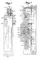
- the base 12 of the feeder drive assembly 10 has a guide channel 24 through which the empty substrate 3 is redirected from the front or forward end of the feeder (the left end as viewed in Figure 1) toward the rear of the feeder (the right end as viewed in Figure 1).
- a cutter 25 ( Figure 6) may be provided to sever the empty substrate 3 at a point just after the pick-up station so as to facilitate interchanging of supply and peel assemblies 50 with a drive assembly 10, as may be better understood by referring to Figure 7.
- a backing member 30 is biased by spring metal member 31 into engagement with the underside of a tape pocket 4 which is situated at the pick-up station in order to ensure good contact of the vacuum spindle with the component 9 during pick-up thereof.
- Member 30 may also have an ejection pin 32 for penetrating the bottom of a pocket and overcoming static electricity or the like which might hinder retrieval of a component 9 from the pocket 4.
- Ejector pin 32 is normally biased downwardly by a spring or the like and is extended into a pocket 4 of the substrate 3 by means of fluid pressure through hose 324.
- the tape 2 is advanced or fed incrementally by raising feed pins 38 so as to engage them in indexing holes 6 of substrate 3, whereafter feed pins 38 are displaced to the left from the position of Figure 15 so as to advance the tape to the left. Then, feed pins 38 are withdrawn from the indexing holes of the substrate and moved to the right (as viewed in these Figures) before again being raised into engagement with other indexing holes 6 in preparation for another cycle of indexed feeding. Thus, feed pins 38 are moved back and forth and up and down in a sequence which describes a counterclockwise, square path of travel.
- a particular advantage of the apparatus of the invention is that at least sideways the forward and backward movement of the feed pins 38 is provided by pneumatic cylinder 22 so that the stroke or back and forth displacement of feed pins 38 may be controlled by an adjustable stop 20.
- the square motion indexing assembly 33 which supports feed pins 38, includes a plate 16 which is slidably supported by wheels 14 (best seen in Figure 6), with slide support 16 being connected to piston rod 23 of cylinder 22 for movement back and forth according to actuation of cylinder 22.
- a forward stop 18 ensures the location of a pocket at the pick-up station at the end of forward stroking, and rearward stop 20 is adjustable by a screw 21 or the like to change a limit of the stroking length and provide that drive assembly 10 (as seen in Figure 7) can accommodate supply and peel assemblies 50 (also seen in Figure 7) which require indexing steps of different lengths. This is particularly significant since supply and peel assemblies 50 of generally the same structure can handle tapes 2 requiring feeding steps which differ in length from tape to tape. Since the indexing holes 6 are always spaced the same, from tape to tape, it is only necessary to vary the stroke of drive cylinder 22 in order to accommodate different feeding step lengths defined by different center-to-center distances between sequential pockets 4 of a tape 2.
- Each interchangeable supply and peel assembly 50 has a tape guide plate 53 ( Figures 9 and 10) which is slidably receivable in a channel 26 ( Figures 5 and 7) of the drive assembly 10.
- the edges of channel 26 are generally defined by members 27 and 29 as seen in Figure 5 and, upon sliding of guide plate 53 fully into channel 26, a spring metal latch 28 ( Figures 2 and 7) latches onto the body portion of the supply and peel assembly 50 to hold it in place.
- Spring metal latch 28 is easily disengaged by hand in order to allow removal of the supply and peel assembly 50 from drive assembly 10.
- supply and peel assembly 50 comprises a base 52 on which is mounted the container 72 for receiving covering material 8 after it has been peeled from substrate 3.
- Base 52 supports lower pulling wheels 75 rotatably and a pivotal arm 73 which, in turn, rotatably supports upper pulling wheels 74.
- Upper pulling wheels 74 are biased into engagement with lower pulling wheels 75 by spring 77 acting on arm 73, and wheels 74 and 75 have intermeshing teeth on their peripheries.
- a one-way clutch 78 ( Figure 3) is operatively associated with the lower wheels 75 and has an eccentricly located pin 80 which is receivable within slot 84 of peeling drive link 82.
- Link 82 is slidably attached to base 52 via slots 86 and pins 87 and is biased to the front of the device by tension spring 92 connected at one end to pin 54 of base 52 and at the other end to pin 90 of link 82.
- the front or forward end of drive link 82 has a pin 88 for a purpose yet to be described.
- the upper wheels 74 have a space therebetween into which extends a tape stripper 76 (Figure 2) to ensure that the covering material 8 being pulled by the wheels does not get wrapped therearound.
- Lower tape pulling wheels 75 likewise are spaced and provided with a stripper 76.
- the front end of base 52 of the supply and peel assembly 50 has the aforementioned tape guide plate 53 affixed thereto, and the reader's attention is directed to Figures 8-10 for the structure of tape guide plate 53 and other members attached thereto.
- a spring metal piece 58 is attached to guide plate 53 and has a locator pin 60 depending therefrom which is engagable in an indexing hole 6 of the substrate 3, as will be described later.
- a peeler arm 62 is slidably attached to guide plate 53 by means of slot 66 and pin 67, and an actuating pin 64 depends from peeler arm 62 through a slot 55 of guide plate 53.
- peeler arm 62 supports a laterally projecting guide 68 around which the covering material 8 is guided and reversed in direction when using the feeder.
- a shutter 70 also projects from peeler arm 62 and is spaced from and slightly forward of cover guiding member 68.
- a stop assembly 63 provides a rearward limit of sliding to arm 62 and overhangs the rear end thereof.
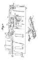
- shutter 70 is still positioned at a pick-up station ( Figure 12) so as to cover a component 9 which is in a pocket 4 from which the cover material 8 was removed in a previous peeling step. With peeler arm 62 in the position of Figure 12, covering material 8 is still covering the next pocket after the pocket which is covered by shutter 70.
- peeler arm 62 Upon peeling the cover material 8 from this next pocket, peeler arm 62 is displaced to the position of Figure 13 so that shutter 70 uncovers the component 9 situated at the pick-up station for retrieval thereof by a vacuum spindle 98 as seen in Figure 14.
- cover material 8 With feed pins 38 disengaged from the indexing holes 6 of the tape and with substrate 3 restrained by locator pin 64 as seen in Figures 13 and 14, cover material 8 is pulled to the right and peeled from substrate 3 while causing retraction of peeler guide 68.
- Retraction of the square motion indexer 33 displaces link 82 against the bias of spring 92 via engagement of one of the arms 37 of the square motion indexing assembly 33 with pin 88 of link 82.
- One-way clutch 78 is drivingly engaged with lower wheels 75 only when rotated in the clockwise direction of Figure 14.
- Pin 80 of clutch 78 rides in a slot 84 of link 82 so that displacement of link 82 to the right against the bias of spring 92 causes clockwise rotation of clutch 78 which, in turn, rotates lower wheels 75 clockwise.
- upper wheels 74 are also rotated, and the intermeshed teeth of wheels 74 and 75 cooperate to pull on the cover material 8 passing between them so as to peel it from the substrate 3.
- Peeling guide 68 is pulled by the tension on cover material 8 so as to retract arm 62 to the right, along with shutter 70, to the position of Figure 14.
- Covering material 8 passes around guide 68, between it and shutter 70, with shutter 70 being sufficiently close to guide 68 that the shutter recloses a pocket as it is being opened by peeling cover 8 therefrom.
- shutter 70 is retracted from the pick-up station at which it is positioned over an already peeled pocket ( Figure 12) to the position of Figure 13 in which the pocket at the pick-up station is uncovered and the next unpeeled pocket is covered by shutter 70.
- a piston slide valve 36 has attached thereto an arm 42 for supporting roller 40 and a member 39 for supporting feed fingers 38 and pin 41.
- Piston 36 is slidably received within cylinder 35 which, in turn, is attached to base 34 and slide plate 16.
- Base 34 is also provided with inverted L-shaped arms 37 against which springs 46 bear to bias member 39, and thus fingers 38 and pin 41, downwardly as illustrated in Figures 14 and 16.
- one-way clutch 78 is rotated counterclockwise (to the position of Figure 16) by way of pin 80 riding in slot 84 of link 82.
- clutch 78 is rotated in this direction, it is disengaged from peeling wheels 75 so that the peeling wheels 74 and 75 are reversely rotatable by a leftward pull on cover 8 during feeding of tape 2.
- peeling tension in cover material 8 is removed during indexed feeding of the tape.
- about half of the length of the covering material 8 which was pushed into box 72 during peeling was retracted back out of box 72 during tape feeding in order to relieve tension in the cover material 8 that otherwise would be caused by the feeding step.
- slider valve piston 36 has a supply orifice 362 and upper and lower exhaust guiding slots 364 and 366.
- Slider valve cylinder 35 has top and bottom exhaust orifices 351 and 354, top and bottom supply orifices 356 and 358, upper and lower middle orifices 352 and 353, and an input/exhaust fitting 368 by which fluid is admitted to cylinder 35 in order to raise piston 36 against the bias of springs 46.
- the base 34 of the square motion indexer 33 has upper and lower exhausts 342 and 344, a forward (extend) supply duct 346, and a reverse (retract) supply duct 348.
- the supporting slide 16 for the square motion indexer 33 is provided with a T-fitting 162, a supply hose 164, and a hose 166 to supply fluid to poppet valve 322.
- Poppet valve 322 ( Figures 3 and 4) has an actuation button 323 and a hose 324 ( Figures 1, 4, 6, and 7) for directing fluid to pusher pin 32 according to actuation of button 323.
- drive cylinder 22 has a fitting 224 by way of which fluid for retracting piston 23 is passed from a hose connected to fitting 45 which, in turn, is connected to supply duct 348 of base 34 of the square motion indexing assembly.
- piston 23 is extended when fluid is supplied to fitting 222 of cylinder 22 via the hose which is connected to fitting 44 which, in turn, is connected to duct 346.
- a spring member 96 may be used to return a similar peeler guide to the forward, extended position upon relief of tension in cover material 8.
Landscapes
- Engineering & Computer Science (AREA)
- Manufacturing & Machinery (AREA)
- Microelectronics & Electronic Packaging (AREA)
- Supply And Installment Of Electrical Components (AREA)
Applications Claiming Priority (1)
| Application Number | Priority Date | Filing Date | Title |
|---|---|---|---|
| US07/201,040 US4869393A (en) | 1988-06-01 | 1988-06-01 | Method and apparatus for peeling a covering tape from a component supply tape |
Publications (1)
| Publication Number | Publication Date |
|---|---|
| EP0414978A1 true EP0414978A1 (de) | 1991-03-06 |
Family
ID=22744221
Family Applications (1)
| Application Number | Title | Priority Date | Filing Date |
|---|---|---|---|
| EP89402387A Ceased EP0414978A1 (de) | 1988-06-01 | 1989-09-01 | Verfahren und Vorrichtung zum Abziehen eines Abdeckbandes von einem Zuführungsgurt von Bauelementen |
Country Status (2)
| Country | Link |
|---|---|
| US (1) | US4869393A (de) |
| EP (1) | EP0414978A1 (de) |
Families Citing this family (9)
| Publication number | Priority date | Publication date | Assignee | Title |
|---|---|---|---|---|
| DE8807239U1 (de) * | 1988-06-03 | 1988-11-03 | Fritsch, Adalbert, 8455 Kastl | Gurtmagazin für SMD-Manipulatoren |
| US5191693A (en) * | 1989-12-29 | 1993-03-09 | Canon Kabushiki Kaisha | Tape type work conveying method and conveying apparatus |
| DE69215778T2 (de) * | 1991-07-19 | 1997-04-10 | Matsushita Electric Ind Co Ltd | Vorrichtung zum Zuführen elektronischer Bauelemente |
| JP2714294B2 (ja) * | 1991-12-19 | 1998-02-16 | 三洋電機株式会社 | 部品供給装置 |
| JPH09186487A (ja) * | 1995-12-28 | 1997-07-15 | Matsushita Electric Ind Co Ltd | 部品供給装置 |
| US6918175B1 (en) * | 1998-03-26 | 2005-07-19 | Siemens Aktiengesellschaft | Supply module for feeding electrical components to an automatic placement device |
| US7073696B2 (en) * | 2003-11-24 | 2006-07-11 | Tyco Electronics Corporation | High repeatability tape feeder for electronic component carrier tapes |
| US9209442B1 (en) | 2014-06-09 | 2015-12-08 | Akoio, Llc | Product dispenser |
| CN107710905B (zh) * | 2015-06-18 | 2019-11-15 | 株式会社富士 | 带切断处理装置及处理方法 |
Citations (4)
| Publication number | Priority date | Publication date | Assignee | Title |
|---|---|---|---|---|
| US4440355A (en) * | 1981-02-23 | 1984-04-03 | Matsushita Electric Industrial Co., Ltd. | Electronic component supply apparatus |
| EP0165487A2 (de) * | 1984-05-21 | 1985-12-27 | Hitachi, Ltd. | Vorrichtung zum Abliefern von Teilen auf Folienband |
| US4586670A (en) * | 1984-12-17 | 1986-05-06 | Usm Corporation | Tape stripper for electrical component tape feeder |
| EP0246153A2 (de) * | 1986-05-12 | 1987-11-19 | UNIVERSAL INSTRUMENTS CORPORATION (Delaware Corp.) | Zuführvorrichtung für Gurte zum Versorgen von elektrischen Bauelementen |
Family Cites Families (2)
| Publication number | Priority date | Publication date | Assignee | Title |
|---|---|---|---|---|
| NL8103573A (nl) * | 1981-07-29 | 1983-02-16 | Philips Nv | Inrichting voor het tegelijkertijd toevoeren van meerdere in banden verpakte electrische en/of electronische onderdelen aan een bepaalde positie. |
| US4606117A (en) * | 1983-05-13 | 1986-08-19 | Tdk Corporation | Apparatus for automatically mounting chip type circuit elements on printed circuit boards |
-
1988
- 1988-06-01 US US07/201,040 patent/US4869393A/en not_active Expired - Fee Related
-
1989
- 1989-09-01 EP EP89402387A patent/EP0414978A1/de not_active Ceased
Patent Citations (4)
| Publication number | Priority date | Publication date | Assignee | Title |
|---|---|---|---|---|
| US4440355A (en) * | 1981-02-23 | 1984-04-03 | Matsushita Electric Industrial Co., Ltd. | Electronic component supply apparatus |
| EP0165487A2 (de) * | 1984-05-21 | 1985-12-27 | Hitachi, Ltd. | Vorrichtung zum Abliefern von Teilen auf Folienband |
| US4586670A (en) * | 1984-12-17 | 1986-05-06 | Usm Corporation | Tape stripper for electrical component tape feeder |
| EP0246153A2 (de) * | 1986-05-12 | 1987-11-19 | UNIVERSAL INSTRUMENTS CORPORATION (Delaware Corp.) | Zuführvorrichtung für Gurte zum Versorgen von elektrischen Bauelementen |
Also Published As
| Publication number | Publication date |
|---|---|
| US4869393A (en) | 1989-09-26 |
Similar Documents
| Publication | Publication Date | Title |
|---|---|---|
| US4887778A (en) | Feeder drive assembly and replaceable section for tape supplying and cover peeling | |
| US4494902A (en) | Method of and device for feeding electric and/or electronic elements to given positions | |
| US5725140A (en) | Tape feeder for a surface mount placement system | |
| CA1102661A (en) | Electric cable processing | |
| US4735341A (en) | Feeder for electrical component supply tapes | |
| US4274529A (en) | Feed-retrieve device for sheet boards | |
| US4869393A (en) | Method and apparatus for peeling a covering tape from a component supply tape | |
| TWI779140B (zh) | 膠帶黏貼裝置 | |
| CA1249068A (en) | Machines for handling electrical components | |
| US6196783B1 (en) | Tape feeders and systems using the same | |
| EP1617716A1 (de) | Vorrichtung zum Bereitstellen von Bauteilen | |
| EP0281884B1 (de) | Kassettenladegerät und Arbeitsverfahren | |
| US4497454A (en) | Tape loading machine | |
| JPS5858791B2 (ja) | 非円筒形のスリ−ブを基材上に取付ける装置 | |
| US4122594A (en) | Method for engaging a slider automatically on a slide fastener chain | |
| CN111788877B (zh) | 带自动装填装置及其带连结方法 | |
| US4216052A (en) | Automatic threading mechanism for a cassette loader | |
| GB1603236A (en) | Device for loading film cassettes | |
| CA1314014C (en) | Method and apparatus for peeling a covering tape from a component supply tape | |
| US4131993A (en) | Means for engaging a slider automatically on a slide fastener chain | |
| CA1240412A (en) | Machines for handling electrical components | |
| JP2851647B2 (ja) | 部品供給テープから被覆用テープを剥離するための改良した方法及び装置 | |
| JPS60204440A (ja) | 矢形ラベル自動取付方法および装置 | |
| US6666249B2 (en) | Closure sticker applicator | |
| EP0567718B1 (de) | Einheit zum Schneiden und Verbinden für ein automatisches Kassettenladegerät und damit durchgeführtes Verfahren zum Bandladen |
Legal Events
| Date | Code | Title | Description |
|---|---|---|---|
| PUAI | Public reference made under article 153(3) epc to a published international application that has entered the european phase |
Free format text: ORIGINAL CODE: 0009012 |
|
| AK | Designated contracting states |
Kind code of ref document: A1 Designated state(s): DE FR GB NL |
|
| 17P | Request for examination filed |
Effective date: 19910829 |
|
| 17Q | First examination report despatched |
Effective date: 19930129 |
|
| STAA | Information on the status of an ep patent application or granted ep patent |
Free format text: STATUS: THE APPLICATION HAS BEEN REFUSED |
|
| 18R | Application refused |
Effective date: 19930719 |