EP0415006A2 - Mâchoire avant - Google Patents
Mâchoire avant Download PDFInfo
- Publication number
- EP0415006A2 EP0415006A2 EP90110416A EP90110416A EP0415006A2 EP 0415006 A2 EP0415006 A2 EP 0415006A2 EP 90110416 A EP90110416 A EP 90110416A EP 90110416 A EP90110416 A EP 90110416A EP 0415006 A2 EP0415006 A2 EP 0415006A2
- Authority
- EP
- European Patent Office
- Prior art keywords
- plate
- housing
- control
- control plate
- pull rod
- Prior art date
- Legal status (The legal status is an assumption and is not a legal conclusion. Google has not performed a legal analysis and makes no representation as to the accuracy of the status listed.)
- Granted
Links
Images


Classifications
-
- A—HUMAN NECESSITIES
- A63—SPORTS; GAMES; AMUSEMENTS
- A63C—SKATES; SKIS; ROLLER SKATES; DESIGN OR LAYOUT OF COURTS, RINKS OR THE LIKE
- A63C9/00—Ski bindings
- A63C9/08—Ski bindings yieldable or self-releasing in the event of an accident, i.e. safety bindings
- A63C9/085—Ski bindings yieldable or self-releasing in the event of an accident, i.e. safety bindings with sole hold-downs, e.g. swingable
- A63C9/08557—Details of the release mechanism
- A63C9/08571—Details of the release mechanism using axis and lever
-
- A—HUMAN NECESSITIES
- A63—SPORTS; GAMES; AMUSEMENTS
- A63C—SKATES; SKIS; ROLLER SKATES; DESIGN OR LAYOUT OF COURTS, RINKS OR THE LIKE
- A63C9/00—Ski bindings
- A63C9/08—Ski bindings yieldable or self-releasing in the event of an accident, i.e. safety bindings
- A63C9/085—Ski bindings yieldable or self-releasing in the event of an accident, i.e. safety bindings with sole hold-downs, e.g. swingable
- A63C9/08507—Ski bindings yieldable or self-releasing in the event of an accident, i.e. safety bindings with sole hold-downs, e.g. swingable with a plurality of mobile jaws
- A63C9/08521—Ski bindings yieldable or self-releasing in the event of an accident, i.e. safety bindings with sole hold-downs, e.g. swingable with a plurality of mobile jaws pivoting about a vertical axis, e.g. side release
-
- A—HUMAN NECESSITIES
- A63—SPORTS; GAMES; AMUSEMENTS
- A63C—SKATES; SKIS; ROLLER SKATES; DESIGN OR LAYOUT OF COURTS, RINKS OR THE LIKE
- A63C9/00—Ski bindings
- A63C9/08—Ski bindings yieldable or self-releasing in the event of an accident, i.e. safety bindings
- A63C9/085—Ski bindings yieldable or self-releasing in the event of an accident, i.e. safety bindings with sole hold-downs, e.g. swingable
- A63C9/08557—Details of the release mechanism
- A63C9/08564—Details of the release mechanism using cam or slide surface
-
- A—HUMAN NECESSITIES
- A63—SPORTS; GAMES; AMUSEMENTS
- A63C—SKATES; SKIS; ROLLER SKATES; DESIGN OR LAYOUT OF COURTS, RINKS OR THE LIKE
- A63C9/00—Ski bindings
- A63C9/001—Anti-friction devices
Definitions
- the invention relates to a toe piece according to the preamble of claim 1.
- DE-PS 29 05 837 describes a toe piece in which a release spring is preloaded when the weight of the skier is shifted forward by means of a pedal, an actuating rod and a control gear.
- a release spring is preloaded when the weight of the skier is shifted forward by means of a pedal, an actuating rod and a control gear.
- the work to be done by the shell-like sole holder is therefore reduced before the sole holder begins its pivoting process.
- this toe piece is complicated in its construction.
- the front jaw according to DE-OS 20 30 749 differs from the previously discussed embodiments in that the jaw body can be pivoted about an axis running perpendicular to the top of the ski.
- the adjustable release spring which acts on a locking ball, is housed in a hole parallel to the swivel axis.
- the detent ball lies in a recess that extends in the longitudinal direction of the ski and narrows in a wedge shape in a displaceably mounted guide plate to which a toothed rack is fastened, in which a toothed segment engages.
- the latter has a lever arm that can be depressed by the ski boot in the event of a frontal fall of the skier.
- the guide plate is first shifted towards the end of the ski, so that the locking ball is supported in the narrowed area.
- this reduces the force required for triggering, and the cup-shaped sole hold-down, which is fastened to the jaw body, can be pivoted with a lower force than in the case of a pure lintel.
- This front jaw also has numerous components which make its manufacture more difficult.
- the invention has as its object the disadvantages to eliminate the known embodiments and to create a toe piece in which - in contrast to the last three exemplary embodiments - the reduction in the work of swiveling out which is required in the case of a forward turning fall should not be caused by compression of the release spring. Rather, the preload of the release spring should be constant, regardless of whether it is a pure lintel or a lintel combined with a frontal lintel.
- this object is achieved according to the invention by the features of the characterizing part of this claim. Due to the fact that the control plate has two webs arranged one above the other, which are different in width, the triggering of the front jaw takes place according to two different characteristics, depending on whether a rotary lintel occurs alone or a frontal lintel combined with this. Such a vertical shift of the control plate is, however, much easier to carry out than shifts in the longitudinal direction of the ski, which necessitate a control gear having many individual parts.
- the measure of claim 2 gives the designer the opportunity to create different triggering conditions for the triggering process in a pure lintel and in a lintel combined with a frontal lintel.
- the feature of claim 4 ensures a good transition of the upper control surface pair of the control plate into its lower control surface pair.
- the measure of claim 5 ensures that the shorter lever arm of the pivoting angle lever rests on the associated control surface. It also prevents canting from occurring in the lower region of this lever arm.
- the subject of claim 6 enables an advantageous transmission of the force required for adjusting the control plate, which originates from the skier.
- the feature of claim 7 allows a play-free mounting of the free end of the pedal in the recess of the control plate without causing the pedal to bend.
- the measure of claim 8 ensures a reliable return of the control plate after a frontal fall into its initial position. In addition, it is ensured that there can be no striking of the control plate on the plate-shaped extension of the housing or striking of the pull rod on the transverse wall of the housing.
- the object of claim 9 ensures, in addition to a secure mounting of the pull rod, a continuous support of the same during the adjustment process in the vertical plane.
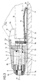
- FIG. 1 is a vertical longitudinal central section through the front jaw in the driving position
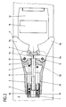
- Fig. 2 is a plan view of the same partly in section along the line II - II in Fig. 1
- Fig. 3 is a vertical longitudinal central section through the front jaw in the event of a frontal fall of the
- FIG. 4 shows a top view of the toe piece, partly in section along the line IV-IV in FIG. 3, when the skier also loses a turn with the frontal fall. 5 shows a detail of the toe piece in the diagram.
- the front jaw is designated 1 in its entirety. It has a housing 2 which is fastened to a ski 3 by means of screws 4.
- the housing 2 is provided towards a ski boot 16 with a plate-shaped extension 2a which extends below the sole of the boot.
- a bore 2b is recessed in the housing 2, in which a release spring 5 designed as a helical spring is accommodated. This is supported at one end on a transverse wall 2c of the housing 2 and at its other end on a piston-like spring plate 6, which can be adjusted by means of a threaded sleeve 7 in the direction of the axis of the release spring 5 and which is guided in the bore 2b.
- the threaded sleeve 7 rests with a surface 7a designed as a spherical zone on a correspondingly designed counter surface 6a of the spring plate 6.
- the threaded sleeve 7 is screwed onto a tie rod 8, which the Trigger spring 5 passes through the center, protrudes through a vertical elongated hole 2d of the transverse wall 2c of the housing 2 and carries a control plate 9 at its rear end.
- two vertical axes 10, on which angle levers 11 are mounted are fixed symmetrically to the vertical longitudinal median plane of the front jaw 1 (cf. in particular FIG. 2). These angle levers 11 rest with their shorter lever arms 11a on the front of the control plate 9 and with their longer lever arms 11b on the ski boot 16.
- the shorter lever arms 11a, viewed in cross section, are rectangular, each lever arm being chamfered at an acute angle ⁇ in the lower region of its side surface facing the control plate 9.
- a pedal 12 provided with a sliding plate 15 is articulated by means of an axis 13.
- the free end of the pedal 12 protrudes into a recess 9a of the control plate 9.
- This recess 9a slidably receives the free end of the pedal 12 and widens in a wedge shape towards the axis 13 of the pedal 12.
- a spring 14 e.g. in the form of a rubber block, which tends to push the pedal 12 upwards, so that the pull rod 8 rests against the upper end of the elongated hole 2d in the transverse wall 2c.
- the control plate 9 is cuboid.
- the lower side of the front of the control plate 9 facing the shorter lever arms 11a has two symmetrically with respect to the vertical longitudinal center plane of the front jaw 1 orderly, vertically running control surfaces 9b delimited by circular cylindrical surfaces, which are separated from one another by a web 9c 1 .
- the two upper control surfaces 9e have upper sections 9e 1 formed by circular cylindrical surfaces and subsequent lower sections 9e 2 , which are formed by toroidal surfaces.
- the radii of the upper circular cylindrical surfaces 9e 1 are larger than the radii of the lower control surfaces 9b.
- the two control surfaces 9e are separated from one another by a web 9c 2 , which is narrower than the lower web 9c 1 .
- the transition between the upper web 9c 2 and the lower web 9c 1 is formed by the two toroidal surfaces 9e 2 of the control surfaces 9e (see FIG. 5).
- control plate 9 is pulled backwards against the force of the release spring 5 until one of the two shorter lever arms 11a leaves the lower web 9c 1 and slides along the associated cylindrical control surface 9b.
- the pedal 12 is first pivoted against the force of the spring 14 in the direction of the upper side 3a of the ski 3, the control plate 9 being pulled downward.
- the pivoting movement of the pedal 12 is limited by the dimensioning of the spring 14, so that neither the tie rod 8 at the lower end of the elongated hole 2d in the transverse wall 2c of the housing 2, the control plate 9 can still rest on the plate-shaped extension 2a of the housing 2. The occurrence of undesirable frictional forces is thus avoided with certainty during a triggering process.
- the shorter lever arms 11a of the two angle levers 11 come to rest against the upper, narrower web 9c 2 .
- the piston-like spring plate for the release spring could be screwed directly onto the pull rod and be provided with a cambered lateral surface with which the spring plate is guided into the bore of the housing and which enables the pull rod to be pivoted in the vertical plane.
- Another spring for example a coil spring or a plate spring assembly, could also be arranged below the pedal.
- the control plate is connected to the two webs with two sinusoidal in cross section control surfaces or with two flat inclined surfaces. In all cases, it is advisable to round off the transitions between the webs and the control surfaces.
Landscapes
- Footwear And Its Accessory, Manufacturing Method And Apparatuses (AREA)
- Fittings On The Vehicle Exterior For Carrying Loads, And Devices For Holding Or Mounting Articles (AREA)
Applications Claiming Priority (2)
| Application Number | Priority Date | Filing Date | Title |
|---|---|---|---|
| AT2062/89 | 1989-09-01 | ||
| AT0206289A AT396067B (de) | 1989-09-01 | 1989-09-01 | Vorderbacken |
Publications (3)
| Publication Number | Publication Date |
|---|---|
| EP0415006A2 true EP0415006A2 (fr) | 1991-03-06 |
| EP0415006A3 EP0415006A3 (en) | 1991-11-27 |
| EP0415006B1 EP0415006B1 (fr) | 1994-11-09 |
Family
ID=3526966
Family Applications (1)
| Application Number | Title | Priority Date | Filing Date |
|---|---|---|---|
| EP90110416A Expired - Lifetime EP0415006B1 (fr) | 1989-09-01 | 1990-06-01 | Mâchoire avant |
Country Status (5)
| Country | Link |
|---|---|
| EP (1) | EP0415006B1 (fr) |
| JP (1) | JPH03170178A (fr) |
| AT (1) | AT396067B (fr) |
| DE (1) | DE59007683D1 (fr) |
| RU (1) | RU2014861C1 (fr) |
Cited By (3)
| Publication number | Priority date | Publication date | Assignee | Title |
|---|---|---|---|---|
| EP0547531A1 (fr) * | 1991-12-19 | 1993-06-23 | HTM Sport- und Freizeitgeräte Aktiengesellschaft | Machoire avant |
| US5257798A (en) * | 1991-03-28 | 1993-11-02 | Htm Sport-Und Freizeitgeraete Gesellschaft M.B.H. | Front jaw |
| US5344180A (en) * | 1992-07-31 | 1994-09-06 | Salomon S.A. | Safety ski binding |
Family Cites Families (3)
| Publication number | Priority date | Publication date | Assignee | Title |
|---|---|---|---|---|
| DE2448769C2 (de) * | 1974-10-12 | 1982-08-26 | Geze Gmbh, 7250 Leonberg | Haltevorrichtung für Sicherheitsskibindungen |
| AT347310B (de) * | 1977-03-24 | 1978-12-27 | Smolka & Co Wiener Metall | Vorderbacken |
| AT385673B (de) * | 1986-06-27 | 1988-05-10 | Tyrolia Freizeitgeraete | Vorderbacken fuer sicherheitsskibindungen |
-
1989
- 1989-09-01 AT AT0206289A patent/AT396067B/de not_active IP Right Cessation
-
1990
- 1990-06-01 DE DE59007683T patent/DE59007683D1/de not_active Expired - Fee Related
- 1990-06-01 EP EP90110416A patent/EP0415006B1/fr not_active Expired - Lifetime
- 1990-08-31 RU SU904830984A patent/RU2014861C1/ru active
- 1990-08-31 JP JP2232258A patent/JPH03170178A/ja active Pending
Cited By (3)
| Publication number | Priority date | Publication date | Assignee | Title |
|---|---|---|---|---|
| US5257798A (en) * | 1991-03-28 | 1993-11-02 | Htm Sport-Und Freizeitgeraete Gesellschaft M.B.H. | Front jaw |
| EP0547531A1 (fr) * | 1991-12-19 | 1993-06-23 | HTM Sport- und Freizeitgeräte Aktiengesellschaft | Machoire avant |
| US5344180A (en) * | 1992-07-31 | 1994-09-06 | Salomon S.A. | Safety ski binding |
Also Published As
| Publication number | Publication date |
|---|---|
| DE59007683D1 (de) | 1994-12-15 |
| JPH03170178A (ja) | 1991-07-23 |
| RU2014861C1 (ru) | 1994-06-30 |
| AT396067B (de) | 1993-05-25 |
| ATA206289A (de) | 1992-07-15 |
| EP0415006A3 (en) | 1991-11-27 |
| EP0415006B1 (fr) | 1994-11-09 |
Similar Documents
| Publication | Publication Date | Title |
|---|---|---|
| DE3039699C2 (fr) | ||
| EP3566754B1 (fr) | Butée avant de fixation de ski | |
| DE2759839C2 (de) | Vorderbacken | |
| DE3102010A1 (de) | "sicherheitsskibindung" | |
| EP3120903A1 (fr) | Talonnière | |
| DE2359490B2 (de) | Vorderer Bindungsteil einer Sicherheitsbindung für Ski | |
| DE3838045A1 (de) | Pedal mit sicherheitseinrichtung fuer ein rennfahrrad | |
| DE2758658A1 (de) | Skibremse | |
| DE2448769C2 (de) | Haltevorrichtung für Sicherheitsskibindungen | |
| EP0415006B1 (fr) | Mâchoire avant | |
| DE2907365C2 (de) | Langlauf-Sicherheitsskibindung | |
| AT398042B (de) | Vorderbacken | |
| AT396065B (de) | Vorderbacken | |
| EP0636196B1 (fr) | Machoire avant d'une fixation de securite pour ski | |
| EP0466860B1 (fr) | Elements de fixation de ski, en particulier machoires avant | |
| EP0547531B1 (fr) | Machoire avant | |
| DE3141021C2 (fr) | ||
| DE2600858B2 (de) | Skisicherheitsbindung mit einer mit dem Schuh lösbar verbundenen Trittplatte | |
| DE2254522B2 (de) | Vorderabstuetzvorrichtung fuer sicherheits-skibindungen | |
| WO1987007516A2 (fr) | Fixation de securite pour ski | |
| DE2321816B2 (de) | Sicherheits-Skibindung mit einer Auslöseplatte | |
| DE2819105C3 (de) | Vorrichtung zum Biegen von Baustahlmatten | |
| EP3851174A1 (fr) | Butée avant pour une fixation de ski | |
| EP0250809A2 (fr) | Mâchoires avant de fixation de sécurité pour ski | |
| EP0324933A2 (fr) | Mâchoire de mesure d'une fixation de sécurité pour ski |
Legal Events
| Date | Code | Title | Description |
|---|---|---|---|
| PUAI | Public reference made under article 153(3) epc to a published international application that has entered the european phase |
Free format text: ORIGINAL CODE: 0009012 |
|
| AK | Designated contracting states |
Kind code of ref document: A2 Designated state(s): CH DE FR LI |
|
| PUAL | Search report despatched |
Free format text: ORIGINAL CODE: 0009013 |
|
| RAP1 | Party data changed (applicant data changed or rights of an application transferred) |
Owner name: TMC CORPORATION |
|
| AK | Designated contracting states |
Kind code of ref document: A3 Designated state(s): CH DE FR LI |
|
| 17P | Request for examination filed |
Effective date: 19920506 |
|
| RAP1 | Party data changed (applicant data changed or rights of an application transferred) |
Owner name: HTM SPORT- UND FREIZEITGERAETE GESELLSCHAFT M.B.H. |
|
| 17Q | First examination report despatched |
Effective date: 19930713 |
|
| RAP1 | Party data changed (applicant data changed or rights of an application transferred) |
Owner name: HTM SPORT- UND FREIZEITGERAETE AKTIENGESELLSCHAFT |
|
| GRAA | (expected) grant |
Free format text: ORIGINAL CODE: 0009210 |
|
| AK | Designated contracting states |
Kind code of ref document: B1 Designated state(s): CH DE FR LI |
|
| REF | Corresponds to: |
Ref document number: 59007683 Country of ref document: DE Date of ref document: 19941215 |
|
| ET | Fr: translation filed | ||
| PGFP | Annual fee paid to national office [announced via postgrant information from national office to epo] |
Ref country code: CH Payment date: 19950630 Year of fee payment: 6 |
|
| PLBE | No opposition filed within time limit |
Free format text: ORIGINAL CODE: 0009261 |
|
| STAA | Information on the status of an ep patent application or granted ep patent |
Free format text: STATUS: NO OPPOSITION FILED WITHIN TIME LIMIT |
|
| 26N | No opposition filed | ||
| PG25 | Lapsed in a contracting state [announced via postgrant information from national office to epo] |
Ref country code: LI Effective date: 19960630 Ref country code: CH Effective date: 19960630 |
|
| REG | Reference to a national code |
Ref country code: CH Ref legal event code: PL |
|
| PGFP | Annual fee paid to national office [announced via postgrant information from national office to epo] |
Ref country code: DE Payment date: 20070622 Year of fee payment: 18 |
|
| PGFP | Annual fee paid to national office [announced via postgrant information from national office to epo] |
Ref country code: FR Payment date: 20070615 Year of fee payment: 18 |
|
| REG | Reference to a national code |
Ref country code: FR Ref legal event code: ST Effective date: 20090228 |
|
| PG25 | Lapsed in a contracting state [announced via postgrant information from national office to epo] |
Ref country code: DE Free format text: LAPSE BECAUSE OF NON-PAYMENT OF DUE FEES Effective date: 20090101 |
|
| PG25 | Lapsed in a contracting state [announced via postgrant information from national office to epo] |
Ref country code: FR Free format text: LAPSE BECAUSE OF NON-PAYMENT OF DUE FEES Effective date: 20080630 |