EP0415076A2 - Aspirateur - Google Patents
Aspirateur Download PDFInfo
- Publication number
- EP0415076A2 EP0415076A2 EP90114232A EP90114232A EP0415076A2 EP 0415076 A2 EP0415076 A2 EP 0415076A2 EP 90114232 A EP90114232 A EP 90114232A EP 90114232 A EP90114232 A EP 90114232A EP 0415076 A2 EP0415076 A2 EP 0415076A2
- Authority
- EP
- European Patent Office
- Prior art keywords
- motor
- flow
- cooling air
- housing
- components
- Prior art date
- Legal status (The legal status is an assumption and is not a legal conclusion. Google has not performed a legal analysis and makes no representation as to the accuracy of the status listed.)
- Granted
Links
- 238000001816 cooling Methods 0.000 claims abstract description 25
- 238000004804 winding Methods 0.000 description 4
- 230000010354 integration Effects 0.000 description 2
- 238000007789 sealing Methods 0.000 description 2
- 238000010276 construction Methods 0.000 description 1
- 230000007547 defect Effects 0.000 description 1
- 238000009413 insulation Methods 0.000 description 1
- 230000008439 repair process Effects 0.000 description 1
- 238000011144 upstream manufacturing Methods 0.000 description 1
Images


Classifications
-
- A—HUMAN NECESSITIES
- A47—FURNITURE; DOMESTIC ARTICLES OR APPLIANCES; COFFEE MILLS; SPICE MILLS; SUCTION CLEANERS IN GENERAL
- A47L—DOMESTIC WASHING OR CLEANING; SUCTION CLEANERS IN GENERAL
- A47L9/00—Details or accessories of suction cleaners, e.g. mechanical means for controlling the suction or for effecting pulsating action; Storing devices specially adapted to suction cleaners or parts thereof; Carrying-vehicles specially adapted for suction cleaners
- A47L9/28—Installation of the electric equipment, e.g. adaptation or attachment to the suction cleaner; Controlling suction cleaners by electric means
- A47L9/2836—Installation of the electric equipment, e.g. adaptation or attachment to the suction cleaner; Controlling suction cleaners by electric means characterised by the parts which are controlled
- A47L9/2842—Suction motors or blowers
Definitions
- the invention relates to a vacuum cleaner with an electric motor, which is fastened between a lower carrier plate and an upper clamping plate, further with electrical or electronic components fastened to circuit boards in the flow housing and with an intake duct and an exhaust duct for the engine cooling air.
- the invention is therefore based on the object of proposing such a vacuum cleaner which is distinguished in particular by a significantly increased service life of the electrical and electronic components.
- the components should also be arranged in a housing in a space-saving and easily replaceable manner.
- the invention is characterized in that when the electric motor is designed as a commutatorless DC motor, at least one of the boards with its components is arranged in the intake duct for the engine cooling air, the intake duct in runs essentially U-shaped with a first leg in the direction of flow, an adjoining horizontal section and an adjoining second leg which is connected airtight to the upper part of the electric motor.
- circuit boards with their components can thus be accommodated in the first leg, in the horizontal section and / or in the second leg, and the engine cooling air flows directly through them and cools them well. They can also be easily replaced, as will be explained in more detail below.
- the parts are also easy to replace.
- the intake duct is placed with its one nozzle (first leg) on the already existing intake opening for the suction of the cooling air for the engine on the motor clamping plate and with the other nozzle (second leg) it is directly connected to the stator of the with the interposition of a sealing ring Motor attached and connected to it in an air-tight manner.
- control electronics In the event of defects and repairs, the entire unit with the entire control electronics can be used. can be easily replaced.
- the control electronics are fully located in the cooling air flow for the engine, upstream of the engine.
- this also ensures that vacuum cleaners which have been in operation so far can be retrofitted with such a unit.
- the existing AC motor simply has to be replaced by the new type of commutatorless DC motor, and the flow housing with the electronics integrated therein is then simply placed on the already existing motor chuck.
- Each motor is then connected to such a flow housing, with the control of each motor being implemented separately via the circuit electronics arranged in the respective flow housing.
- the motor-side socket of the housing with the electronics integrated on it is air-tight with the upper part, i.e. So is connected to the fixed winding part of the motor and that an outlet cross-section is formed around the motor in the clamping plate, so that this ensures that the cooling air is guided inward into the motor through the flow housing, flows through the motor to the Windings flow past, is diverted by approx. 1800 and flows out in the opposite direction to the incoming cooling air on the outside of the flow-through housing, appropriate sound insulation mats being arranged here in the outflow channel formed by the clamping plate and hood in order to dampen the engine noise.
- this exhaust air / air flow is then discharged via labyrinth channels arranged in the hood of the vacuum cleaner.
- corresponding protruding angles are provided on the side wall of the flow channel, which have bores through which screws pass, which screws are screwed into the top of the clamping plate.
- angles in the flow housing itself can be integrated, the flow housing having, for example, bores in its base plate, through which screws can be screwed then also reach into the clamping plate.
- An electric motor 31 is clamped in an easily replaceable manner between a lower carrier plate 32 and an upper clamping plate 33, the electric motor being held in a vibration-damped manner via rubber elements 34. From Figure 1, the turbine 35 of the vacuum cleaner can also be seen, which is placed directly below the actual electric motor 31.
- the flow of the engine cooling air is indicated in FIG. 1 with MK, the flow of the engine exhaust air with MA, the flow of the suction supply air with SZ and the flow of the suction exhaust air with SA.
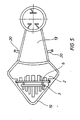
- a flow housing 1 for the engine cooling air according to FIG. 3 is open at the top and has an upper edge 21.
- the upper cover of this housing 1 with respect to the upper edge 21 is formed by the inside of the hood of the vacuum cleaner, not shown. This means that the housing 1 is closed on all sides and only has one connector 2 and the other connector 17.
- the wall 19 which is approximately angled in plan view, is omitted and this wall 19 itself is formed by the wall of the hood or the clamping plate of the vacuum cleaner.
- the flow-through housing 1 is only flowed through by the engine cooling air.
- the turbine intake air and the turbine exhaust air are routed separately in the exhaust air ducts between the clamping plate and the carrier plate.
- the present invention is therefore about the guidance of the engine cooling air and the arrangement of the electronic circuit parts in the area of this flow housing.
- FIG 3 is shown schematically that the housing essentially (see Figure 4 and Figure 5) consists of two connecting pieces or legs 2, 17, which form a mutual distance from each other.
- a heat sink 3 with cooling fins 4 is arranged in the connecting piece 2, transistors 8 being firmly connected to the heat sink 3 on the side faces of this heat sink.
- This heat sink is thus fully in the flow of the intake cooling air, which enters the nozzle 2 in the direction of arrow 12 from below.
- the cooling air occurs in several cross sections, namely once in the gap 9 between the heat sink 3 and the outer wall 19 of the housing, further in the gap 10 between the back of the heat sink 3 and the back of a circuit board 6 and further in the gap 11 between the front of the Board 6 and the inner wall of the connector 2.
- the wall 19 can be omitted and appropriate sealing measures are then provided at position 22, because then in this area the connector 2 rests air-tight on the inside of the hood and the connector 2 on the one hand through the wall of the hood and on the other hand through remaining walls of the housing 1 is formed.
- This board 15 essentially carries the mains rectifier 16 with heat sinks, cooling fins and the like. Components to be cooled more.
- the air then flows in the direction of the arrow 18 and then flows into the nozzle 17, where the nozzle on its lower edge 23 is also air-tight is connected to the fixed part of the motor, so that the air in the direction of arrow 18 then flows through the winding of the motor.
- the electronics to be cooled could also be arranged directly on the clamping plate and in the incoming cooling air flow of the motor.
- appropriate electronic parts to be cooled can also be arranged in this area, such as, for. B. a mains interference filter, an automatic switch-on and switch-off for switching the vacuum motor on and off in the event of a fault, and an automatic switch-off for switching off a tool, which is then switched off when the vacuum cleaner falls below a certain minimum volume flow.
Landscapes
- Engineering & Computer Science (AREA)
- Mechanical Engineering (AREA)
- Motor Or Generator Cooling System (AREA)
- Motor Or Generator Frames (AREA)
- Filters For Electric Vacuum Cleaners (AREA)
- Electric Suction Cleaners (AREA)
- Electric Vacuum Cleaner (AREA)
- Brushless Motors (AREA)
- Electrical Discharge Machining, Electrochemical Machining, And Combined Machining (AREA)
- Crystals, And After-Treatments Of Crystals (AREA)
Applications Claiming Priority (2)
| Application Number | Priority Date | Filing Date | Title |
|---|---|---|---|
| DE3928313A DE3928313A1 (de) | 1989-08-26 | 1989-08-26 | Schmutzsauger |
| DE3928313 | 1989-08-26 |
Publications (3)
| Publication Number | Publication Date |
|---|---|
| EP0415076A2 true EP0415076A2 (fr) | 1991-03-06 |
| EP0415076A3 EP0415076A3 (en) | 1992-06-03 |
| EP0415076B1 EP0415076B1 (fr) | 1995-01-11 |
Family
ID=6387987
Family Applications (1)
| Application Number | Title | Priority Date | Filing Date |
|---|---|---|---|
| EP90114232A Expired - Lifetime EP0415076B1 (fr) | 1989-08-26 | 1990-07-25 | Aspirateur |
Country Status (7)
| Country | Link |
|---|---|
| US (1) | US5068555A (fr) |
| EP (1) | EP0415076B1 (fr) |
| JP (1) | JPH0724644B2 (fr) |
| KR (1) | KR0146362B1 (fr) |
| AT (1) | ATE116825T1 (fr) |
| BR (1) | BR9004193A (fr) |
| DE (2) | DE3928313A1 (fr) |
Cited By (5)
| Publication number | Priority date | Publication date | Assignee | Title |
|---|---|---|---|---|
| EP0510597A1 (fr) * | 1991-04-22 | 1992-10-28 | Hitachi, Ltd. | Aspirateur de poussières |
| WO2010042563A3 (fr) * | 2008-10-06 | 2010-06-10 | Shop Vac Corporation | Ensemble aspirateur pour automobile |
| WO2017137329A1 (fr) * | 2016-02-09 | 2017-08-17 | Arcelik Anonim Sirketi | Aspirateur présentant une meilleure performance de fonctionnement |
| EP3398498A1 (fr) * | 2017-05-02 | 2018-11-07 | TROTEC GmbH & Co. KG | Appareil de séchage de couche isolante |
| EP3409166A1 (fr) * | 2017-05-29 | 2018-12-05 | BSH Hausgeräte GmbH | Canal d'évacuation pour un aspirateur et aspirateur comportant un tel canal d'évacuation |
Families Citing this family (19)
| Publication number | Priority date | Publication date | Assignee | Title |
|---|---|---|---|---|
| US5245237A (en) * | 1992-03-19 | 1993-09-14 | General Electric Company | Two compartment motor |
| US5353469A (en) * | 1992-07-01 | 1994-10-11 | National Super Service Company | Wet/dry vacuum cleaner with noise reducing housing structure |
| US5479676A (en) * | 1994-05-12 | 1996-01-02 | Electrolux Corporation | Vacuum cleaner |
| US5813085A (en) * | 1997-02-25 | 1998-09-29 | White Consolidated Industries, Inc. | Motor isolation gasket for central vacuum |
| US6003200A (en) * | 1997-11-14 | 1999-12-21 | Overhead Door Corporation | Powerhead housing assembly for vacuum cleaner |
| DE29805994U1 (de) * | 1998-04-02 | 1999-06-17 | Wap Reinigungssysteme Gmbh & Co, 89287 Bellenberg | Elektronisch kommutierter Motor für Scheuersaugmaschinen |
| US6155801A (en) * | 1999-03-18 | 2000-12-05 | Elnar; Joseph G. | Air blower assembly for spas |
| AU2003215456A1 (en) | 2002-03-12 | 2003-09-22 | Cube Investments Limited | Suction motor for vacuum cleaner |
| US6856113B1 (en) | 2004-05-12 | 2005-02-15 | Cube Investments Limited | Central vacuum cleaning system motor control circuit mounting post, mounting configuration, and mounting methods |
| EP1799087A4 (fr) | 2004-09-17 | 2009-08-12 | Cube Invest Ltd | Poignee d'un dispositif de nettoyage et sections boitier de poignee de dispositif de nettoyage |
| US7199496B2 (en) * | 2005-01-18 | 2007-04-03 | Oriental Motor Boston Technology Group Incorporated | Integrated electric motor and drive, optimized for high-temperature operation |
| CA2562804C (fr) | 2005-10-07 | 2014-12-09 | Cube Investments Limited | Commandes croisees d'aspirateur central |
| US7900315B2 (en) * | 2005-10-07 | 2011-03-08 | Cube Investments Limited | Integrated central vacuum cleaner suction device and control |
| US7690075B2 (en) | 2005-10-07 | 2010-04-06 | Cube Investments Limited | Central vacuum cleaner control, unit and system with contaminant sensor |
| CA2562810C (fr) * | 2005-10-07 | 2015-12-08 | Cube Investments Limited | Commande de sources d'aspiration multiples d'aspirateur central |
| US20090126146A1 (en) * | 2007-10-03 | 2009-05-21 | Overvaag Chad D | Vacuum cleaner with heat sink in air path |
| JP5425596B2 (ja) * | 2009-11-20 | 2014-02-26 | カルソニックカンセイ株式会社 | アクチュエータ装置のモータ制振構造 |
| US10085606B2 (en) | 2013-04-08 | 2018-10-02 | Emerson Electric Co. | Systems and apparatuses for cooling a vacuum device |
| US10164505B2 (en) * | 2016-01-19 | 2018-12-25 | Nidec Motor Corporation | Forced air cooling of vacuum motor control |
Family Cites Families (11)
| Publication number | Priority date | Publication date | Assignee | Title |
|---|---|---|---|---|
| FR1497396A (fr) * | 1965-10-28 | 1967-10-06 | Gen Electric | Perfectionnements apportés aux aspirateurs |
| DE1588432A1 (de) * | 1967-04-07 | 1970-05-21 | Licentia Gmbh | Durch Halbleiter gesteuerter Elektromotor |
| DE1905624C3 (de) * | 1969-02-05 | 1978-07-13 | Siemens Ag, 1000 Berlin Und 8000 Muenchen | Zahnärztliches Bohrhandstück |
| JPS4730208U (fr) * | 1971-04-26 | 1972-12-06 | ||
| US4195969A (en) * | 1978-01-05 | 1980-04-01 | Clarke-Gravely Corporation | Vacuum cleaner |
| DE3225258C2 (de) * | 1982-07-06 | 1985-11-28 | Guido Oberdorfer Wap-Maschinen, 7919 Bellenberg | Schmutzsauger |
| JPS61109539A (ja) * | 1984-11-02 | 1986-05-28 | 松下電器産業株式会社 | 電気掃除機 |
| JPS61272026A (ja) * | 1985-05-29 | 1986-12-02 | 松下電器産業株式会社 | 電気掃除機 |
| DE8704717U1 (de) * | 1987-03-31 | 1988-02-25 | Zubler Gerätebau GmbH, 7910 Neu-Ulm | Kollektorloser Industriesauger |
| DE8704712U1 (de) * | 1987-03-31 | 1987-10-08 | Zubler Gerätebau GmbH, 7910 Neu-Ulm | Elektromotor mit wenigstens einem zugeordneten Gebläse |
| DE3710619A1 (de) * | 1987-03-31 | 1988-10-20 | Zubler Geraetebau | Industriesauger mit integriertem umrichter zur versorgung von handwerkzeugen |
-
1989
- 1989-08-26 DE DE3928313A patent/DE3928313A1/de not_active Withdrawn
-
1990
- 1990-07-25 EP EP90114232A patent/EP0415076B1/fr not_active Expired - Lifetime
- 1990-07-25 AT AT90114232T patent/ATE116825T1/de not_active IP Right Cessation
- 1990-07-25 DE DE59008233T patent/DE59008233D1/de not_active Expired - Fee Related
- 1990-08-13 US US07/566,735 patent/US5068555A/en not_active Expired - Fee Related
- 1990-08-23 KR KR1019900013050A patent/KR0146362B1/ko not_active Expired - Fee Related
- 1990-08-24 BR BR909004193A patent/BR9004193A/pt not_active IP Right Cessation
- 1990-08-27 JP JP2226400A patent/JPH0724644B2/ja not_active Expired - Lifetime
Cited By (10)
| Publication number | Priority date | Publication date | Assignee | Title |
|---|---|---|---|---|
| EP0510597A1 (fr) * | 1991-04-22 | 1992-10-28 | Hitachi, Ltd. | Aspirateur de poussières |
| WO2010042563A3 (fr) * | 2008-10-06 | 2010-06-10 | Shop Vac Corporation | Ensemble aspirateur pour automobile |
| US8286300B2 (en) | 2008-10-06 | 2012-10-16 | Shop Vac Corporation | System and method of controlling current draw of a switched reluctance motor |
| US8312590B2 (en) | 2008-10-06 | 2012-11-20 | Shop Vac Corporation | System and method of controlling start-up of a switched reluctance motor |
| US8615845B2 (en) | 2008-10-06 | 2013-12-31 | Shop Vac Corporation | Vacuum assembly for automobile |
| US9238451B2 (en) | 2008-10-06 | 2016-01-19 | Shop Vac Corporation | Vacuum assembly with inlet through removable tank |
| US10618502B2 (en) | 2008-10-06 | 2020-04-14 | Shop Vac Corporation | Vacuum assembly for automobile |
| WO2017137329A1 (fr) * | 2016-02-09 | 2017-08-17 | Arcelik Anonim Sirketi | Aspirateur présentant une meilleure performance de fonctionnement |
| EP3398498A1 (fr) * | 2017-05-02 | 2018-11-07 | TROTEC GmbH & Co. KG | Appareil de séchage de couche isolante |
| EP3409166A1 (fr) * | 2017-05-29 | 2018-12-05 | BSH Hausgeräte GmbH | Canal d'évacuation pour un aspirateur et aspirateur comportant un tel canal d'évacuation |
Also Published As
| Publication number | Publication date |
|---|---|
| ATE116825T1 (de) | 1995-01-15 |
| KR0146362B1 (ko) | 1998-08-01 |
| US5068555A (en) | 1991-11-26 |
| EP0415076A3 (en) | 1992-06-03 |
| EP0415076B1 (fr) | 1995-01-11 |
| BR9004193A (pt) | 1991-09-03 |
| JPH0724644B2 (ja) | 1995-03-22 |
| KR910004239A (ko) | 1991-03-28 |
| DE3928313A1 (de) | 1991-02-28 |
| DE59008233D1 (de) | 1995-02-23 |
| JPH03139319A (ja) | 1991-06-13 |
Similar Documents
| Publication | Publication Date | Title |
|---|---|---|
| EP0415076B1 (fr) | Aspirateur | |
| EP0497296B1 (fr) | Installation de filtre-ventilateur pour l'utilisation dans des salles blanches | |
| WO1999040766A1 (fr) | Ventilateur destine a etre monte sur un element de paroi d'une armoire de commande | |
| EP0942639A2 (fr) | Armoire électronique ventilée | |
| DE102012007707B4 (de) | Kühlgerät für die Schaltschrankkühlung | |
| DE102008042897A1 (de) | Gebläseeinrichtung für ein Fahrzeug | |
| DE102015226389B4 (de) | Leistungsumsetzer und damit ausgerüstetes Schienenfahrzeug | |
| DE19709145C1 (de) | Zweiteilige Wärmetauschereinrichtung | |
| DE212019000013U1 (de) | Staubschutz- und Kühlhaube für einen bürstenlosen Elektromotor | |
| EP0940632A1 (fr) | Hotte d'aspiration | |
| DE19737531A1 (de) | Wärmetauscherbausatz | |
| DE60318074T2 (de) | Zentraler staubsauger und seine zentrale einheit | |
| DE60312317T2 (de) | Wasserfiltergerät | |
| DE10038057B4 (de) | Filterlüfter | |
| DE202012003192U1 (de) | Lüftungsanlage | |
| DE202008016601U1 (de) | Vorrichtung zur Kühlung gehauster Räume | |
| DE19709834A1 (de) | Modulare Erzeugungseinheit für gereinigte Gase | |
| DE4226634C2 (de) | Entlüftungsgerät | |
| DE202019005871U1 (de) | Pumpeinrichtung, Hauswasserwerk/-automat und Gartenpumpe | |
| DE102004008513A1 (de) | Lüftersystem für Stromverteileranlagen | |
| DE10210418A1 (de) | Schaltschrank mit Kühleinrichtung | |
| DE202015102781U1 (de) | Lüftungseinrichtung für Reinräume | |
| DE8902015U1 (de) | Luftleitblecheinsatz für einen Schaltschrank | |
| DE102008016164A1 (de) | Absaughaube | |
| DE202024106520U1 (de) | Klimatisierungsgerät zum deckennahen Einbau |
Legal Events
| Date | Code | Title | Description |
|---|---|---|---|
| PUAI | Public reference made under article 153(3) epc to a published international application that has entered the european phase |
Free format text: ORIGINAL CODE: 0009012 |
|
| AK | Designated contracting states |
Kind code of ref document: A2 Designated state(s): AT BE CH DE DK ES FR GB GR IT LI LU NL SE |
|
| PUAL | Search report despatched |
Free format text: ORIGINAL CODE: 0009013 |
|
| AK | Designated contracting states |
Kind code of ref document: A3 Designated state(s): AT BE CH DE DK ES FR GB GR IT LI LU NL SE |
|
| 17P | Request for examination filed |
Effective date: 19920922 |
|
| 17Q | First examination report despatched |
Effective date: 19931008 |
|
| GRAA | (expected) grant |
Free format text: ORIGINAL CODE: 0009210 |
|
| AK | Designated contracting states |
Kind code of ref document: B1 Designated state(s): AT BE CH DE DK ES FR GB GR IT LI LU NL SE |
|
| PG25 | Lapsed in a contracting state [announced via postgrant information from national office to epo] |
Ref country code: BE Effective date: 19950111 Ref country code: IT Free format text: LAPSE BECAUSE OF FAILURE TO SUBMIT A TRANSLATION OF THE DESCRIPTION OR TO PAY THE FEE WITHIN THE PRE;WARNING: LAPSES OF ITALIAN PATENTS WITH EFFECTIVE DATE BEFORE 2007 MAY HAVE OCCURRED AT ANY TIME BEFORE 2007. THE CORRECT EFFECTIVE DATE MAY BE DIFFERENT FROM THE ONE RECORDED.SCRIBED TIME-LIMIT Effective date: 19950111 Ref country code: DK Effective date: 19950111 Ref country code: GB Effective date: 19950111 Ref country code: FR Effective date: 19950111 Ref country code: ES Free format text: THE PATENT HAS BEEN ANNULLED BY A DECISION OF A NATIONAL AUTHORITY Effective date: 19950111 Ref country code: NL Effective date: 19950111 Ref country code: GR Free format text: LAPSE BECAUSE OF FAILURE TO SUBMIT A TRANSLATION OF THE DESCRIPTION OR TO PAY THE FEE WITHIN THE PRESCRIBED TIME-LIMIT Effective date: 19950111 |
|
| REF | Corresponds to: |
Ref document number: 116825 Country of ref document: AT Date of ref document: 19950115 Kind code of ref document: T |
|
| REF | Corresponds to: |
Ref document number: 59008233 Country of ref document: DE Date of ref document: 19950223 |
|
| PG25 | Lapsed in a contracting state [announced via postgrant information from national office to epo] |
Ref country code: SE Effective date: 19950411 |
|
| EN | Fr: translation not filed | ||
| NLV1 | Nl: lapsed or annulled due to failure to fulfill the requirements of art. 29p and 29m of the patents act | ||
| GBV | Gb: ep patent (uk) treated as always having been void in accordance with gb section 77(7)/1977 [no translation filed] |
Effective date: 19950111 |
|
| PG25 | Lapsed in a contracting state [announced via postgrant information from national office to epo] |
Ref country code: AT Effective date: 19950725 |
|
| PG25 | Lapsed in a contracting state [announced via postgrant information from national office to epo] |
Ref country code: LI Effective date: 19950731 Ref country code: CH Effective date: 19950731 Ref country code: LU Free format text: LAPSE BECAUSE OF NON-PAYMENT OF DUE FEES Effective date: 19950731 |
|
| PLBE | No opposition filed within time limit |
Free format text: ORIGINAL CODE: 0009261 |
|
| STAA | Information on the status of an ep patent application or granted ep patent |
Free format text: STATUS: NO OPPOSITION FILED WITHIN TIME LIMIT |
|
| 26N | No opposition filed | ||
| REG | Reference to a national code |
Ref country code: CH Ref legal event code: PL |
|
| PGFP | Annual fee paid to national office [announced via postgrant information from national office to epo] |
Ref country code: DE Payment date: 20050615 Year of fee payment: 16 |
|
| PG25 | Lapsed in a contracting state [announced via postgrant information from national office to epo] |
Ref country code: DE Free format text: LAPSE BECAUSE OF NON-PAYMENT OF DUE FEES Effective date: 20070201 |