EP0415083B1 - Boîtier d'emmagasinage de cassette - Google Patents
Boîtier d'emmagasinage de cassette Download PDFInfo
- Publication number
- EP0415083B1 EP0415083B1 EP19900114366 EP90114366A EP0415083B1 EP 0415083 B1 EP0415083 B1 EP 0415083B1 EP 19900114366 EP19900114366 EP 19900114366 EP 90114366 A EP90114366 A EP 90114366A EP 0415083 B1 EP0415083 B1 EP 0415083B1
- Authority
- EP
- European Patent Office
- Prior art keywords
- cassette
- container case
- recess
- lid
- index card
- Prior art date
- Legal status (The legal status is an assumption and is not a legal conclusion. Google has not performed a legal analysis and makes no representation as to the accuracy of the status listed.)
- Expired - Lifetime
Links
- 238000003780 insertion Methods 0.000 description 5
- 230000037431 insertion Effects 0.000 description 5
- 238000010276 construction Methods 0.000 description 2
- 239000000428 dust Substances 0.000 description 2
- 239000000463 material Substances 0.000 description 2
- 230000003247 decreasing effect Effects 0.000 description 1
- 230000007812 deficiency Effects 0.000 description 1
- 238000004519 manufacturing process Methods 0.000 description 1
- 238000012986 modification Methods 0.000 description 1
- 230000004048 modification Effects 0.000 description 1
- 239000000843 powder Substances 0.000 description 1
- 238000003908 quality control method Methods 0.000 description 1
- 230000000452 restraining effect Effects 0.000 description 1
Images



Classifications
-
- G—PHYSICS
- G11—INFORMATION STORAGE
- G11B—INFORMATION STORAGE BASED ON RELATIVE MOVEMENT BETWEEN RECORD CARRIER AND TRANSDUCER
- G11B23/00—Record carriers not specific to the method of recording or reproducing; Accessories, e.g. containers, specially adapted for co-operation with the recording or reproducing apparatus ; Intermediate mediums; Apparatus or processes specially adapted for their manufacture
- G11B23/02—Containers; Storing means both adapted to cooperate with the recording or reproducing means
- G11B23/023—Containers for magazines or cassettes
- G11B23/0233—Containers for a single cassette
Definitions
- the present invention relates generally to a cassette container case for storing a magnetic tape cassette, and more particularly to an improved cassette container case for storing a standard compact cassette.
- the cassette When storing an audio type magnetic tape cassette, the cassette is generally placed in a magnetic tape cassette container case made of a plastic material.
- the magnetic tape cassette has a front open portion into which a magnetic head, etc., is inserted when loading the cassette into a recording/reproducing device, the magnetic tape running across the front open portion during recording and reproduction.
- dust is liable to enter the cassette through the front open portion, and there is a risk that the user's fingers, etc., may contact the magnetic tape.
- a cassette container case is commonly used.
- Fig. 6 shows the basic construction of a conventional cassette container case.
- the cassette container case 31 has a lid 32 having a pocket portion 34 for receiving a cassette 20, and a casing 35 having a pair of rotation-preventing projections 7 which are adapted to be inserted into respective shaft insertion holes 22 of the cassette 20.
- the lid 32 and the casing 35 can be opened and closed much like a door.
- the thickness of the cassette container case 31 between its walls 33 and 36 opposed respectively to the front and rear faces of the cassette 20 corresponds to the thick portion 21 of a cassette 20 in the region of its front opening. Therefore, except for the thick portion 21, the thickness l1 of the cassette container case 31 is considerably greater than the thickness l2 of the cassette 20.
- recesses for receiving the thick portion of the cassette at the front portion of the cassette are formed in an openable distal portion of the cassette container case.
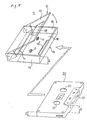
- the improved cassette container case disclosed in U.S. Patent 4,627,534 and having the precharacterised features of claim 1 will now be described with reference to Fig. 5.
- the cassette container case 11 shown in Fig. 5 has a lid 12 having a pocket portion 14, and a casing 15 which is pivotally connected to the lid 12 as in the conventional cassette container case.
- a recess 18 for receiving the thick portion 21 of a cassette 20 is formed in a wall 13 of the lid 12 opposed to the face of the cassette.
- Another recess 18′ for receiving the thick portion 21 of the cassette is also formed in a wall 16 of the casing 15 opposed to the face of the cassette.
- a pair of rotation-preventing projections 7, similar to those of the conventional cassette case, which are insertable into reel shaft insertion holes 22 are also formed on the wall 16.
- each recess 18 or 18′ is shaped to receive the thick portion 21, that is, each recess has a shape (for example, a trapezoidal shape) flaring outward away from the axis of rotation (opening and closing movement) of the lid 12 and the casing 15.
- protrusions are formed on right and left side walls 19 of the casing 15, and respective depressions are formed in right and left side walls of the pocket portion 14 opposed to the walls 19.
- the protrusions are engageable in the depressions when the lid of the cassette container case 11 is closed, thereby preventing the lid from being accidentally opened during the storage of the cassette.
- the spacing between the wall 13 and the wall 16 is only slightly greater than the thickness l2 of the cassette 20 in areas other than the thick portion 21, and the spacing between the two recesses 18 and 18′ is only slightly greater than the thickness l5 of the thick portion 21.
- the improved cassette container case 11 shown in Fig. 5 has a much smaller thickness than the earlier cassette container case, the space required for storing it is much reduced, and the improved case is very handy for carrying.
- An index card 41 as shown in Fig. 4 is attached to the cassette container case 31 shown in Fig. 6, and desired data can be written on the index card 41. More specifically, the index card is positioned in such a manner that a folded portion 42 of a channel-shaped cross-section is fitted in the pocket portion 34, with a flat portion 43 laid over the flat wall 33 of the lid 32.
- the index card 41 when the index card 41 is applied to the improved cassette container case 11 shown in Fig. 5, a problem is encountered. That is, since the recesses 18 are provided at the open side of the thin-type cassette container case 11, when the index card 41 is provided on the lid 12, the recess 18 formed in the lid 12 is blocked by the index card, defeating the function of this recess 18.
- the present inventor has disclosed an index card 51, as shown in Fig. 4, which avoids closing the recess 18.
- the index care 51 of Fig. 4 has a folded portion 52 for fitting in the pocket portion 14 similar to that of the earlier index card, but a flat portion 53 is smaller in width than the above-mentioned flat portion 43. More specifically, there is established the relationship L b ⁇ L a - L c where L a represents the width of the flat portion 43, L b the width of the flat portion 53, and L c the depth (width) of the recess 18. With this arrangement, the recess 18 formed in the open side of the lid 12 is not closed by the index card, so that the thick portion 21 of the cassette can be received in this recess.
- the lid 12 is exposed at opposite sides of the recess 18, and a step is formed between such exposed portion and the portion where the index card 51 is present. This produces instabilities such as rattling. Moreover, powder tends to be produced as a result of the frictional contact between the cassette 20 and the lid 12. This is not desirable from the viewpoints of quality control and appearance.
- An object of the present invention is to overcome the above deficiencies, and more specifically an object of the invention is to provide a thin-type cassette container case which can stably hold a magnetic tape cassette despite the provision of recesses for receiving the thick portion of a cassette.
- Fig. 1 is a developed, perspective view of an index card for use in the cassette container case of a preferred embodiment of the invention.
- Fig. 2 is a perspective view of the index card.
- Fig. 3 is a perspective view of the case having the index card attached thereto.
- the index card in this embodiment is designed to be attached to the cassette container case 11 shown in Fig. 5, and therefore this embodiment will be explained with reference to this cassette container case 11.
- the index card 1 comprises an elongated thick paper sheet cut from a paper blank, the thick paper sheet having an opening 2 of a hexagonal shape formed therethrough.
- the thick paper sheet is folded inwardly at portions thereof indicated by dashed lines a , b and c .
- the area of the opening 2 is twice that of the recess 18, and the shape of the opening 2 is determined in accordance with the shape of the recess 18.
- the position of the opening 2 is such that the opening 2 is disposed in registry with the recess 18 when the index card 1 is attached to the lid 12.
- a pocket insertion portion 3 of a channel-shaped cross-section is formed as shown in Fig. 2.
- the hexagonal opening 2 is converted into an opening 2a whose area is half that of the hexagonal opening 2.
- the opening 2a corresponds to the recess 18.
- the width L b of a doubled flat portion 4 is substantially equal to the above-mentioned width L a .
- the cassette container case 11 having the index card 1 attached thereto will now be described.
- the pocket insertion portion 3 of the index card 1 is inserted into the pocket 14 portion of the lid 12.
- the doubled flat portion 4 is positioned so as to be laid over the wall 13 so that the recess 18 is exposed at part of the wall 13 through the opening 2a. Therefore, when the cassette 20 is inserted into the lid 12 as indicated by an arrow in Fig. 5, one side (the upper side in Fig. 5) of the thick portion 21 passes through the opening 2a and is received in the recess 18.
- the flat portion 4 of the index card 1 is not limited to the doubled form, and may be in a single form.
- the opening 2 is beforehand formed into a trapezoidal shape corresponding to the recess 18.
- the opening 2 may be slightly smaller in size than the recess 18 so that when the thick portion 21 passes through the opening 2, the edge portion of the opening 2 is turned or folded toward the recess 18. In this case, part of the index card 1 is interposed between the edge portion of the thick portion 21 and the edge portion of the recess 18, thereby further restraining rattling.
- the lid having the pocket portion is pivotally connected to the casing having the rotation-preventing projections in such a manner that the lid and the casing can be opened and closed like a door, and the index card having the opening or the open area located so as not to cover the recesses formed in the open sides of the lid and the casing is attached to the lid.
- the thick portion of the cassette passes through the opening or the open area of the index card and is received in the recess. Therefore, despite the fact that the index card is attached to the cassette container case, the cassette container case can be made thin as a whole.
- the index card also serves as a cushioning material so that rattling of the cassette is reduced, thereby decreasing the production of unpleasant noise and frictional contact between the cassette and the case.
Landscapes
- Packaging Of Annular Or Rod-Shaped Articles, Wearing Apparel, Cassettes, Or The Like (AREA)
Claims (5)
- Boîte de cassette (11) comportant : un boîtier (15), un couvercle (12) ayant une partie de logement destinée à recevoir une cassette compacte standard (20) et relié de façon pivotante audit boîtier d'une manière telle que ledit couvercle et ledit boîtier peuvent être ouverts et fermés à la manière d'une porte, un renfoncement (18) destiné à recevoir une partie épaisse (21) de ladite cassette et qui est formé au moins dans ledit couvercle; et un carton de repère (1) reçu dans ledit couvercle, caractérisé en ce que ledit carton de repère est de la même taille que le couvercle avec une partie découpée qui se conforme audit renfoncement.
- Boîte de cassette selon la revendication 1, dans laquelle ledit boîtier comporte une paire de saillies empêchant la rotation (7) formées dessus afin d'empêcher la rotation de moyeux (22) de ladite cassette contenue dans ladite boîte de cassette.
- Boîte de cassette selon la revendication 1, dans laquelle un autre renfoncement (18') est formé dans ledit boîtier à l'opposé du renfoncement (18) dans le couvercle.
- Boîte de cassette selon la revendication 1, dans laquelle ledit carton de repère est plié deux fois dans sa position opérationnelle, ledit carton de repère dans un état déplié ayant un trou de forme hexagonale formé de façon symétrique de chaque côté de la ligne de pliage et ayant sensiblement deux fois la section dudit renfoncement.
- Boîte de cassette selon la revendication 4, dans laquelle ledit trou est légèrement plus petit que ledit renfoncement.
Applications Claiming Priority (4)
| Application Number | Priority Date | Filing Date | Title |
|---|---|---|---|
| JP1989101845U JP2504527Y2 (ja) | 1989-09-01 | 1989-09-01 | カセット収納ケ―ス |
| JP101845/89U | 1989-09-01 | ||
| JP1989106599U JPH0743030Y2 (ja) | 1989-09-13 | 1989-09-13 | カセット収納ケース |
| JP106599/89U | 1989-09-13 |
Publications (3)
| Publication Number | Publication Date |
|---|---|
| EP0415083A2 EP0415083A2 (fr) | 1991-03-06 |
| EP0415083A3 EP0415083A3 (en) | 1991-11-27 |
| EP0415083B1 true EP0415083B1 (fr) | 1994-09-28 |
Family
ID=26442628
Family Applications (1)
| Application Number | Title | Priority Date | Filing Date |
|---|---|---|---|
| EP19900114366 Expired - Lifetime EP0415083B1 (fr) | 1989-09-01 | 1990-07-26 | Boîtier d'emmagasinage de cassette |
Country Status (2)
| Country | Link |
|---|---|
| EP (1) | EP0415083B1 (fr) |
| DE (1) | DE69012930T2 (fr) |
Families Citing this family (6)
| Publication number | Priority date | Publication date | Assignee | Title |
|---|---|---|---|---|
| US5154287A (en) * | 1991-01-10 | 1992-10-13 | Fuji Photo Film Co., Ltd. | Cassette accommodating case |
| US5160028A (en) * | 1991-01-10 | 1992-11-03 | Fuji Photo Film Co., Ltd. | Magnetic tape cassette accommodating case |
| JP2547726Y2 (ja) * | 1991-07-19 | 1997-09-17 | 富士写真フイルム株式会社 | 磁気テープカセット用収納ケース |
| DE9109068U1 (de) * | 1991-07-23 | 1991-11-14 | Weber, Christoph, 8919 Greifenberg | Falteinlage für Leerkassettenbox |
| EP0677846B1 (fr) * | 1994-04-08 | 2000-03-08 | Fuji Photo Film Co., Ltd. | Contenaire pour accomoder une cassette à bande magnétique ayant une carte index facilement déformable |
| JP3002897U (ja) * | 1994-04-08 | 1994-10-04 | 富士写真フイルム株式会社 | 磁気テープカセット用収納ケース |
Family Cites Families (6)
| Publication number | Priority date | Publication date | Assignee | Title |
|---|---|---|---|---|
| US3638788A (en) * | 1969-10-09 | 1972-02-01 | Solomon Nathan | Cassette cover |
| CH559955A5 (en) * | 1972-09-06 | 1975-03-14 | Idn Invention Dev Novelties | Flat tape cassette container - has sliding drawer for cassette with identification label and with side walls for cassette engagement |
| US4385693A (en) * | 1981-02-27 | 1983-05-31 | Gelardi Anthony L | Origin identity insert for packaged cassettes |
| JPS57177287U (fr) * | 1981-04-28 | 1982-11-09 | ||
| JPS60163279U (ja) * | 1984-04-06 | 1985-10-30 | 富士写真フイルム株式会社 | 磁気テ−プカセツト用収納ケ−ス |
| JPH03100187U (fr) * | 1990-01-31 | 1991-10-18 |
-
1990
- 1990-07-26 EP EP19900114366 patent/EP0415083B1/fr not_active Expired - Lifetime
- 1990-07-26 DE DE1990612930 patent/DE69012930T2/de not_active Expired - Fee Related
Also Published As
| Publication number | Publication date |
|---|---|
| EP0415083A2 (fr) | 1991-03-06 |
| DE69012930D1 (de) | 1994-11-03 |
| EP0415083A3 (en) | 1991-11-27 |
| DE69012930T2 (de) | 1995-02-02 |
Similar Documents
| Publication | Publication Date | Title |
|---|---|---|
| US4627534A (en) | Magnetic tape cassette storage case | |
| US4648507A (en) | Magnetic tape cassette storage case | |
| JPH0268374U (fr) | ||
| EP0415083A2 (fr) | Boîtier d'emmagasinage de cassette | |
| US4661865A (en) | Battery holder of single head minimum size cassette tape player | |
| US5450960A (en) | Cassette containing case with an index card | |
| US5109982A (en) | Cassette container case with recessed walls | |
| US5042659A (en) | Case for magnetic tape cassette | |
| EP0649141A2 (fr) | Boîtier pour cassette à bande magnétique | |
| JP2547726Y2 (ja) | 磁気テープカセット用収納ケース | |
| US5899330A (en) | Encasing mechanism for a cassette enclosing a magnetic record medium | |
| US5360105A (en) | Container case for magnetic tape cassette | |
| JPH0637195U (ja) | 磁気テープカセット用収納ケース | |
| JPH0743030Y2 (ja) | カセット収納ケース | |
| JP3319260B2 (ja) | ディスク収納ケース | |
| JP2677262B2 (ja) | カセットケース | |
| JPS6013816Y2 (ja) | 磁気テ−プカ−トリツジの収納箱 | |
| JP3278357B2 (ja) | ディスクカートリッジ収納ケース | |
| JP2723049B2 (ja) | カセット収納ケース | |
| JP2570218B2 (ja) | インデックスシート | |
| JPH0617756Y2 (ja) | カセット収納ケース | |
| JP2624163B2 (ja) | カセットケース | |
| JP3508041B2 (ja) | ディスクカートリッジ | |
| JP2528584Y2 (ja) | 磁気テープカセット用収納ケース | |
| JP2528583Y2 (ja) | 磁気テープカセット用収納ケース |
Legal Events
| Date | Code | Title | Description |
|---|---|---|---|
| PUAI | Public reference made under article 153(3) epc to a published international application that has entered the european phase |
Free format text: ORIGINAL CODE: 0009012 |
|
| AK | Designated contracting states |
Kind code of ref document: A2 Designated state(s): DE GB |
|
| PUAL | Search report despatched |
Free format text: ORIGINAL CODE: 0009013 |
|
| AK | Designated contracting states |
Kind code of ref document: A3 Designated state(s): DE GB |
|
| 17P | Request for examination filed |
Effective date: 19920527 |
|
| 17Q | First examination report despatched |
Effective date: 19931118 |
|
| GRAA | (expected) grant |
Free format text: ORIGINAL CODE: 0009210 |
|
| AK | Designated contracting states |
Kind code of ref document: B1 Designated state(s): DE GB |
|
| REF | Corresponds to: |
Ref document number: 69012930 Country of ref document: DE Date of ref document: 19941103 |
|
| PLBE | No opposition filed within time limit |
Free format text: ORIGINAL CODE: 0009261 |
|
| STAA | Information on the status of an ep patent application or granted ep patent |
Free format text: STATUS: NO OPPOSITION FILED WITHIN TIME LIMIT |
|
| 26N | No opposition filed | ||
| REG | Reference to a national code |
Ref country code: GB Ref legal event code: IF02 |
|
| REG | Reference to a national code |
Ref country code: GB Ref legal event code: 732E |
|
| PGFP | Annual fee paid to national office [announced via postgrant information from national office to epo] |
Ref country code: DE Payment date: 20080807 Year of fee payment: 19 |
|
| PGFP | Annual fee paid to national office [announced via postgrant information from national office to epo] |
Ref country code: GB Payment date: 20080806 Year of fee payment: 19 |
|
| GBPC | Gb: european patent ceased through non-payment of renewal fee |
Effective date: 20090726 |
|
| PG25 | Lapsed in a contracting state [announced via postgrant information from national office to epo] |
Ref country code: GB Free format text: LAPSE BECAUSE OF NON-PAYMENT OF DUE FEES Effective date: 20090726 |
|
| PG25 | Lapsed in a contracting state [announced via postgrant information from national office to epo] |
Ref country code: DE Free format text: LAPSE BECAUSE OF NON-PAYMENT OF DUE FEES Effective date: 20100202 |