EP0415486A1 - Procédé et appareil pour la purification électrostatique d'effluents de gaz nocifs et poussiéreux dans des séparateurs à plusieurs champs - Google Patents
Procédé et appareil pour la purification électrostatique d'effluents de gaz nocifs et poussiéreux dans des séparateurs à plusieurs champs Download PDFInfo
- Publication number
- EP0415486A1 EP0415486A1 EP90202257A EP90202257A EP0415486A1 EP 0415486 A1 EP0415486 A1 EP 0415486A1 EP 90202257 A EP90202257 A EP 90202257A EP 90202257 A EP90202257 A EP 90202257A EP 0415486 A1 EP0415486 A1 EP 0415486A1
- Authority
- EP
- European Patent Office
- Prior art keywords
- stage
- precipitation
- liquid
- electrodes
- precipitation electrodes
- Prior art date
- Legal status (The legal status is an assumption and is not a legal conclusion. Google has not performed a legal analysis and makes no representation as to the accuracy of the status listed.)
- Granted
Links
- 239000007789 gas Substances 0.000 title claims abstract description 94
- 238000000034 method Methods 0.000 title claims abstract description 37
- 238000004140 cleaning Methods 0.000 title claims abstract description 27
- 230000008569 process Effects 0.000 title abstract description 10
- 230000001473 noxious effect Effects 0.000 title 1
- 238000001556 precipitation Methods 0.000 claims abstract description 113
- 239000007788 liquid Substances 0.000 claims abstract description 85
- 239000000428 dust Substances 0.000 claims abstract description 53
- 239000003344 environmental pollutant Substances 0.000 claims abstract description 37
- 231100000719 pollutant Toxicity 0.000 claims abstract description 37
- 239000007921 spray Substances 0.000 claims description 21
- HEMHJVSKTPXQMS-UHFFFAOYSA-M Sodium hydroxide Chemical compound [OH-].[Na+] HEMHJVSKTPXQMS-UHFFFAOYSA-M 0.000 claims description 6
- 239000007864 aqueous solution Substances 0.000 claims description 5
- 239000000725 suspension Substances 0.000 claims description 5
- 238000000926 separation method Methods 0.000 abstract description 8
- 239000010802 sludge Substances 0.000 abstract description 5
- 230000015572 biosynthetic process Effects 0.000 abstract description 2
- 230000002378 acidificating effect Effects 0.000 description 6
- 238000010079 rubber tapping Methods 0.000 description 6
- XLYOFNOQVPJJNP-UHFFFAOYSA-N water Substances O XLYOFNOQVPJJNP-UHFFFAOYSA-N 0.000 description 6
- 230000008901 benefit Effects 0.000 description 5
- 229910052751 metal Inorganic materials 0.000 description 5
- 239000002184 metal Substances 0.000 description 5
- 239000000126 substance Substances 0.000 description 5
- 238000005260 corrosion Methods 0.000 description 4
- 230000007797 corrosion Effects 0.000 description 4
- 230000005684 electric field Effects 0.000 description 4
- 239000002245 particle Substances 0.000 description 4
- 238000001035 drying Methods 0.000 description 3
- 239000012717 electrostatic precipitator Substances 0.000 description 3
- 230000007246 mechanism Effects 0.000 description 3
- 239000007787 solid Substances 0.000 description 3
- 241000282693 Cercopithecidae Species 0.000 description 2
- UQSXHKLRYXJYBZ-UHFFFAOYSA-N Iron oxide Chemical compound [Fe]=O UQSXHKLRYXJYBZ-UHFFFAOYSA-N 0.000 description 2
- 244000089486 Phragmites australis subsp australis Species 0.000 description 2
- 238000004026 adhesive bonding Methods 0.000 description 2
- 230000002411 adverse Effects 0.000 description 2
- 229910052785 arsenic Inorganic materials 0.000 description 2
- 229910052793 cadmium Inorganic materials 0.000 description 2
- 230000000694 effects Effects 0.000 description 2
- 239000012212 insulator Substances 0.000 description 2
- 229910052745 lead Inorganic materials 0.000 description 2
- 229910052753 mercury Inorganic materials 0.000 description 2
- 150000003839 salts Chemical class 0.000 description 2
- 238000005507 spraying Methods 0.000 description 2
- 238000003466 welding Methods 0.000 description 2
- 238000009736 wetting Methods 0.000 description 2
- 229920001817 Agar Polymers 0.000 description 1
- 241000273930 Brevoortia tyrannus Species 0.000 description 1
- 239000000919 ceramic Substances 0.000 description 1
- 230000008859 change Effects 0.000 description 1
- 239000002800 charge carrier Substances 0.000 description 1
- 238000002485 combustion reaction Methods 0.000 description 1
- 230000006835 compression Effects 0.000 description 1
- 238000007906 compression Methods 0.000 description 1
- 238000009833 condensation Methods 0.000 description 1
- 230000005494 condensation Effects 0.000 description 1
- 238000001816 cooling Methods 0.000 description 1
- 239000013078 crystal Substances 0.000 description 1
- 238000002425 crystallisation Methods 0.000 description 1
- 230000008025 crystallization Effects 0.000 description 1
- 238000009826 distribution Methods 0.000 description 1
- -1 ferrous metals Chemical class 0.000 description 1
- 239000000835 fiber Substances 0.000 description 1
- 229910052731 fluorine Inorganic materials 0.000 description 1
- 238000011010 flushing procedure Methods 0.000 description 1
- 239000010881 fly ash Substances 0.000 description 1
- 230000002262 irrigation Effects 0.000 description 1
- 238000003973 irrigation Methods 0.000 description 1
- 238000004519 manufacturing process Methods 0.000 description 1
- 239000000463 material Substances 0.000 description 1
- 230000005012 migration Effects 0.000 description 1
- 238000013508 migration Methods 0.000 description 1
- 229910052759 nickel Inorganic materials 0.000 description 1
- 230000000737 periodic effect Effects 0.000 description 1
- 230000008439 repair process Effects 0.000 description 1
- 238000005245 sintering Methods 0.000 description 1
- 239000002562 thickening agent Substances 0.000 description 1
- 229910052718 tin Inorganic materials 0.000 description 1
- 230000007704 transition Effects 0.000 description 1
- 238000009827 uniform distribution Methods 0.000 description 1
Images



Classifications
-
- B—PERFORMING OPERATIONS; TRANSPORTING
- B03—SEPARATION OF SOLID MATERIALS USING LIQUIDS OR USING PNEUMATIC TABLES OR JIGS; MAGNETIC OR ELECTROSTATIC SEPARATION OF SOLID MATERIALS FROM SOLID MATERIALS OR FLUIDS; SEPARATION BY HIGH-VOLTAGE ELECTRIC FIELDS
- B03C—MAGNETIC OR ELECTROSTATIC SEPARATION OF SOLID MATERIALS FROM SOLID MATERIALS OR FLUIDS; SEPARATION BY HIGH-VOLTAGE ELECTRIC FIELDS
- B03C3/00—Separating dispersed particles from gases or vapour, e.g. air, by electrostatic effect
- B03C3/02—Plant or installations having external electricity supply
- B03C3/16—Plant or installations having external electricity supply wet type
-
- B—PERFORMING OPERATIONS; TRANSPORTING
- B03—SEPARATION OF SOLID MATERIALS USING LIQUIDS OR USING PNEUMATIC TABLES OR JIGS; MAGNETIC OR ELECTROSTATIC SEPARATION OF SOLID MATERIALS FROM SOLID MATERIALS OR FLUIDS; SEPARATION BY HIGH-VOLTAGE ELECTRIC FIELDS
- B03C—MAGNETIC OR ELECTROSTATIC SEPARATION OF SOLID MATERIALS FROM SOLID MATERIALS OR FLUIDS; SEPARATION BY HIGH-VOLTAGE ELECTRIC FIELDS
- B03C3/00—Separating dispersed particles from gases or vapour, e.g. air, by electrostatic effect
- B03C3/34—Constructional details or accessories or operation thereof
- B03C3/40—Electrode constructions
- B03C3/45—Collecting-electrodes
- B03C3/53—Liquid, or liquid-film, electrodes
-
- B—PERFORMING OPERATIONS; TRANSPORTING
- B03—SEPARATION OF SOLID MATERIALS USING LIQUIDS OR USING PNEUMATIC TABLES OR JIGS; MAGNETIC OR ELECTROSTATIC SEPARATION OF SOLID MATERIALS FROM SOLID MATERIALS OR FLUIDS; SEPARATION BY HIGH-VOLTAGE ELECTRIC FIELDS
- B03C—MAGNETIC OR ELECTROSTATIC SEPARATION OF SOLID MATERIALS FROM SOLID MATERIALS OR FLUIDS; SEPARATION BY HIGH-VOLTAGE ELECTRIC FIELDS
- B03C3/00—Separating dispersed particles from gases or vapour, e.g. air, by electrostatic effect
- B03C3/017—Combinations of electrostatic separation with other processes, not otherwise provided for
-
- B—PERFORMING OPERATIONS; TRANSPORTING
- B03—SEPARATION OF SOLID MATERIALS USING LIQUIDS OR USING PNEUMATIC TABLES OR JIGS; MAGNETIC OR ELECTROSTATIC SEPARATION OF SOLID MATERIALS FROM SOLID MATERIALS OR FLUIDS; SEPARATION BY HIGH-VOLTAGE ELECTRIC FIELDS
- B03C—MAGNETIC OR ELECTROSTATIC SEPARATION OF SOLID MATERIALS FROM SOLID MATERIALS OR FLUIDS; SEPARATION BY HIGH-VOLTAGE ELECTRIC FIELDS
- B03C3/00—Separating dispersed particles from gases or vapour, e.g. air, by electrostatic effect
- B03C3/02—Plant or installations having external electricity supply
- B03C3/025—Combinations of electrostatic separators, e.g. in parallel or in series, stacked separators or dry-wet separator combinations
-
- B—PERFORMING OPERATIONS; TRANSPORTING
- B03—SEPARATION OF SOLID MATERIALS USING LIQUIDS OR USING PNEUMATIC TABLES OR JIGS; MAGNETIC OR ELECTROSTATIC SEPARATION OF SOLID MATERIALS FROM SOLID MATERIALS OR FLUIDS; SEPARATION BY HIGH-VOLTAGE ELECTRIC FIELDS
- B03C—MAGNETIC OR ELECTROSTATIC SEPARATION OF SOLID MATERIALS FROM SOLID MATERIALS OR FLUIDS; SEPARATION BY HIGH-VOLTAGE ELECTRIC FIELDS
- B03C3/00—Separating dispersed particles from gases or vapour, e.g. air, by electrostatic effect
- B03C3/34—Constructional details or accessories or operation thereof
- B03C3/74—Cleaning the electrodes
- B03C3/76—Cleaning the electrodes by using a mechanical vibrator, e.g. rapping gear ; by using impact
-
- B—PERFORMING OPERATIONS; TRANSPORTING
- B03—SEPARATION OF SOLID MATERIALS USING LIQUIDS OR USING PNEUMATIC TABLES OR JIGS; MAGNETIC OR ELECTROSTATIC SEPARATION OF SOLID MATERIALS FROM SOLID MATERIALS OR FLUIDS; SEPARATION BY HIGH-VOLTAGE ELECTRIC FIELDS
- B03C—MAGNETIC OR ELECTROSTATIC SEPARATION OF SOLID MATERIALS FROM SOLID MATERIALS OR FLUIDS; SEPARATION BY HIGH-VOLTAGE ELECTRIC FIELDS
- B03C3/00—Separating dispersed particles from gases or vapour, e.g. air, by electrostatic effect
- B03C3/34—Constructional details or accessories or operation thereof
- B03C3/88—Cleaning-out collected particles
Definitions
- the invention relates to a process for the electrostatic cleaning of dust and pollutant-containing exhaust gases in multi-field separators, the exhaust gases in the flow direction being first subjected to dry electrostatic cleaning in gas lanes formed from plate-shaped precipitation electrodes and then in a second stage by one or more Fields with liquid-wetted, gas lanes forming precipitation electrodes are passed and to a device for performing the method.
- GB-PS 988,350 describes a method for electrical dust separation in which a drying tower, one or more dry-working electrical fields and one or more wet-working electrical fields are arranged one behind the other.
- the water sprayed through nozzles into the wet field (s) flows off as cloudy, is thickened by thickener and injected into the drying tower by steam or compressed air, where the evaporated liquid humidifies the hot dryer gas and thus prevents spraying back in the dry working fields.
- US Pat. No. 1,766,422 also describes a process for the electrostatic cleaning of exhaust gases containing dust and pollutants, in which the exhaust gas laden with dust and pollutants is first fed to dry electrostatic cleaning and then to wet electrostatic cleaning.
- the precipitation electrodes are wetted with a treatment liquid in the wet electrostatic cleaning stage.
- the gas velocity in the electrostatic separator is chosen so high that the fine grain fraction is separated in the dry electrostatic cleaning stage, the coarse grain fraction in the wet electrostatic cleaning stage.
- a sludge accumulates in the sump of the wet electrostatic cleaning stage, which in addition to the dust also contains a relatively large amount of pollutants.
- this method has the disadvantage that the exhaust gas is passed through the electrostatic precipitator at a relatively high gas velocity in order to cause the coarse grain fraction of the dust contained in the exhaust gas to be separated in the wet electrostatic cleaning stage.
- This has the consequence that the residence time of the exhaust gas in the wet electrostatic cleaning stage is too short to the pollutants contained in the exhaust gas to such an extent remove that the limit values of TA-Luft from 27.02.1986 for the pollutants in the clean gas can be observed.
- the invention is therefore based on the object to provide a method for the electrostatic cleaning of dust and pollutant-containing exhaust gases in multi-field separators, which the above. Avoids disadvantages and enables a separate separation of dry dust on the one hand and pollutants on the other hand, the pollutants contained in the exhaust gas in the wet electrostatic cleaning stage to be separated as largely as possible dust-free.
- the object on which the invention is based is achieved in that the liquid added in the second stage at the upper ends of the precipitation electrodes is collected directly under the lower ends of the precipitation electrodes and discharged laterally from the separator, and in that the residue which still arises in the second stage is essentially dry dust is fed to a dust collector.
- Dust means the solid particles contained in the exhaust gas; For example, in sintering plants, the dust consists mainly of iron oxide-containing solid particles, and in combustion plants, it consists of the small fly ash particles.
- the term "pollutants" includes the acidic components contained in the exhaust gas such as HF, SO2, SO3 and HCl and the non-ferrous metals such as Pb, Cd present in the exhaust gas in gaseous or sublimed form. Hg and As.
- At least one electric field is arranged in the first stage and in the second stage of the multi-field separator used. With an exhaust gas volume of 100,000 m3 / h, the field strength is 1.5 to 2.5 kV / cm and the total precipitation area of the multi-field separator is in the range of 400 to 700 m2.
- Metal plates, metal nets, plastic mesh or plates made of ceramic can be used as plate-shaped precipitation electrodes Materials are used.
- the liquid applied to the upper ends of the precipitation electrodes in the second stage is an aqueous solution.
- Various types of devices such as dust bunkers, dust collecting channels and discharge elements such as screw conveyors can be used as the dust collecting device.
- the dust still entering the second stage can also be separated dry to a large extent and thus separated from the pollutants. This is achieved in that only the precipitation electrodes are wetted and that the liquid used for sprinkling is drained off immediately below the precipitation electrodes in collecting channels, while the actual gas lane space and the space below the electrodes remain dry. Therefore, only a very small part of the dust gets into the liquid.
- the method has the advantage that the pollutants contained in the exhaust gas are not mixed in the second stage with the substantially dry dust still accumulating in the second stage and are discharged from the separator. In the second stage, there is no sludge loaded with pollutants, the disposal of which is problematic. Furthermore, this method enables the dust resistance to be reduced to such an extent that the phenomenon of back spraying is avoided and dust and pollutants are separated in such a way that the limit values for pollutant concentrations in the clean gas are relatively far below.
- the residence time of the gases in the first stage is 60 to 80% of the total residence time in a multi-field separator.
- This measure has the effect that the gas temperature in the second stage is only approximately the Reduces the temperature difference by which the gas temperature increases again due to the gas compression by the downstream fan.
- the water dew point is raised by only approx. 4 ° C.
- the distance between the gas temperature and the water dew point in the second stage of the multi-field separator is chosen so large that the water dew point is not fallen below and thus the acidic pollutants do not condense on the non-wetted dry parts of the second stage . Special measures to avoid corrosion in the second stage are therefore not necessary.
- the inventive division of the residence time enables the coarse grain fraction of the dust to be separated in the first stage and the fine grain fraction of the dust to be separated in the second stage.
- the process can thus be carried out successfully at low gas velocities, the residence time in the second stage being sufficient to remove the pollutants from the exhaust gas to a sufficient extent.
- a further preferred embodiment of the invention consists in that an alkaline aqueous solution with a pH of 7 to 9 is used as the liquid.
- an alkaline aqueous solution with a pH of 7 to 9 is used as the liquid.
- NaOH and / or KOH and / or Ca (OH) 2 is added to the liquid.
- These substances are readily soluble in water, so that a pH in the range from 7 to 9 can be set quickly and without problems in the aqueous solution.
- the precipitation electrodes are pulsed with a Range of 20 to 400 ms applied.
- the precipitation electrodes are pulsed with a Range of 20 to 400 ms applied.
- only so many DC voltage pulses are switched through to the spray electrode by this measure that just enough charge carriers are generated for the separation of the dust present in the raw gas stream.
- the thyristor is then blocked for a period of 20 to 400 ms, the filter voltage falling exponentially until the next DC voltage pulses are switched through.
- the filter voltage is kept at an optimal lower limit in order to avoid an excessive drop in the filter voltage and thus the driving force for the migration of the charged dust particles to the precipitation electrode.
- the dead space between the precipitation electrodes and the housing wall of the separator is flushed with hot gas in the second stage.
- the hot gas reaches the dead space via nozzles. This prevents condensation of the water vapor contained in the exhaust gas on the walls caused by the temperature falling below the dew point and the associated corrosion of the components of the second stage.
- part of the clean gas discharged from the second stage is used as the hot gas. This measure ensures that pollutants do not get into the second stage of the multi-field separator again by flushing the dead space.
- the injected clean gas is largely free of pollutants, so that corrosion, especially on the walls of the housing of the multi-field separator, is almost completely avoided.
- the spray system of the second stage and / or the housing wall of the second stage is tapped.
- the spray system of the second stage is to be understood as all the spray electrodes of the wet electrostatic cleaning stage and their suspension devices. It has surprisingly been found that the majority of the dust cleaned by the knocking is not deposited on the precipitation electrodes wetted with liquid, but partly in agglomerated form in the dry gas alley space or directly on the housing wall of the second stage and thus falls down is fed directly to the dust collecting device.
- the implementation of the method according to the invention is not limited to the use of a specific tapping device.
- Another embodiment of the invention is that the spray system is tapped once in 2 to 20 minutes.
- the term "minutes" means the minutes when the second stage is switched on. If the spray system is tapped once in 2 to 20 minutes, the spray system is thoroughly cleaned without the actual process of electrostatic cleaning being adversely affected in the second stage.
- the individual spray electrodes or the individual suspension devices of the spray system of a gas lane are tapped one after the other. This has the advantage that strong whirling up of dust and briefly increased dust concentrations in the clean gas are reliably avoided.
- the housing wall of the second stage is tapped once in 20 to 120 minutes.
- the term "minutes" means the switch-on minutes in the operation of the second stage. This measure thoroughly removes the dust from the housing during operation without adversely affecting the process of electrostatic cleaning in the second stage.
- the object on which the invention is based is further achieved by the provision of a device in which the precipitation area of the precipitation electrodes of the second stage is 20 to 45% of the total precipitation area of the separator.
- overflow troughs are arranged at the upper ends of the precipitation electrodes of the second stage and collecting troughs are arranged at the lower ends of the precipitation electrodes of the second stage, the precipitation electrodes of the second stage being fastened to the lower end of the respective overflow troughs.
- the collecting troughs are dimensioned so that they can accommodate the amount of liquid, the throughput of which is usually 40 to 80 m3 / h with an exhaust gas amount of 100,000 m3 / h.
- the overflow channels are dimensioned so that the precipitation electrodes are evenly covered with a Liquid film can be wetted. If the precipitation electrodes of the second stage are attached to the lower end of the respective overflow channels, a uniform wetting of the precipitation electrodes is achieved starting from the upper end of the precipitation electrodes.
- At least one edge of the individual overflow channels is comb-shaped. This measure ensures that the precipitation electrodes are uniformly wetted with a liquid film and that the thickness of the liquid film is approximately constant over the precipitation surface of the respective precipitation electrode. This enables a uniform separation of the pollutants in the second stage, whereby almost the entire precipitation electrode surface is available for the separation of the pollutants and oversizing of the individual precipitation electrode surfaces is not necessary.
- a liquid distributor pipe connected to the liquid supply and provided with openings is arranged in each overflow channel. According to this arrangement, the liquid can be fed to the individual overflow channels directly from above. With this arrangement it is also possible to circulate the liquid.
- each overflow channel is connected to the respective liquid distributor pipe. This measure ensures that each precipitation electrode is connected directly to the respective liquid distribution pipe via the respective overflow channel, which allows quick access to the precipitation electrode during repair work.
- a tube is arranged at the upper end of each precipitation electrode of the second stage, which is connected directly to the precipitation electrode, which has holes on the side facing away from the precipitation electrode in the plane of the precipitation electrode and which is connected to the liquid supply, wherein collecting troughs are arranged at the lower ends of the precipitation electrodes of the second stage.
- the tube can be connected to the precipitation electrode, for example, by welding, gluing or by a screw or rivet connection. It has surprisingly been found that there is no crystal formation when the liquid emerges from the bores, so that a uniform irrigation of the precipitation electrodes is ensured over a long operating time.
- the thickness of the liquid film can also be optimized by changing the amount of liquid supplied. It can also be advantageous to change the throughput of the liquid in a fixed cycle during the continuous supply of the liquid.
- the diameter of the bores is 8 to 12 mm. This measure results in a particularly uniform distribution of the liquid on the respective precipitation electrode.
- the hole spacing of the bores is 20 to 40 mm. If the hole spacing of the bores is 20 to 40 mm, the thickness of the liquid film on the precipitation electrode can be set particularly advantageously, since a liquid film with a constant thickness is already formed on the outer surface of the tube.
- the diameter of the tube is 60 to 140 mm. This has the advantage that when such a tube is used, the usual throughputs for the liquid, which are between 40 and 80 m3 / h with an exhaust gas quantity of 100,000 m3 / h, can be applied to the precipitation electrodes without problems. If the tube has a diameter of 60 to 140 mm, it can be used in many ways, so that the costs for the device according to the invention are reduced by series production of the tube.
- the tube is additionally connected to the precipitation electrode via at least one plate arranged in the longitudinal direction of the tube.
- this measure ensures that the liquid film between the bores of the tube and the precipitation electrode does not tear off, on the other hand the connection between the tube and the precipitation electrode is strengthened.
- Each plate can be connected to the tube and the precipitation electrode, for example by welding, gluing or by a screw or rivet connection.
- At least one plate is connected tangentially to the tube. This measure ensures a continuous transition of the liquid film between the tube and the plate.
- a hot gas supply is arranged in the second stage.
- the arrangement of a hot gas supply in the second stage enables the dead space between the precipitation electrodes and the housing wall of the separator to be flushed with hot gas in the second stage.
- Another embodiment of the invention is that the edges of each precipitation electrode of the second stage are connected to a pipeline which is connected to the liquid supply. This has the advantage that the liquid can be fed directly to the individual precipitation electrodes, the individual gas lanes between the precipitation electrodes being kept free for gas passage, so that the separation process in the second stage of the multi-field separator is not hindered.
- the pipeline is provided with openings on the lower edge of each precipitation electrode of the second stage.
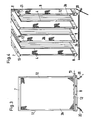
- the exhaust gas loaded with dust and pollutants enters the first stage (1), in which dry electrostatic cleaning takes place, in the direction of the arrow.
- the first stage (1) there are dry working precipitation electrodes (3a) and spray electrodes (4) which are held in a suspension device (18) and are electrically insulated with support insulators (19).
- the dry working precipitation electrodes (3a) of the first stage (1) are cleaned by periodic tapping during operation.
- a dust collecting device (5a) and a discharge device (6a) are provided in the first stage (1) to discharge the dry dust.
- the exhaust gas enters the second stage (2) immediately after the dry electrostatic cleaning.
- the second stage (2) there are precipitation electrodes (3b) and spray electrodes (4) wetted with liquid.
- the precipitation electrodes (3b) and spray electrodes (4) are electrically insulated with post insulators (19).
- the liquid loaded with pollutants runs down the respective precipitation electrode surfaces and reaches the respective collecting troughs (8).
- a dust collecting device (5b) and a discharge device (6b) are provided for separating the dust which is dry in the second stage.
- a hot gas supply (11) is arranged in the second stage (2) of the multi-field separator. The hot gas (21) passes through the nozzles of the hot gas supply (11) into the dead spaces between the precipitation electrodes (3b) and the housing wall [9) of the separator. The clean gas leaves the second stage (2) of the multi-field separator in the direction of the arrow.
- the dust collecting device (5b) is designed according to FIG. 2 as a discharge screw, which feeds the dry dust accumulating in the second stage (2) to a discharge member (6b).
- the liquid, which is collected by the collecting troughs (8) and is loaded with pollutants, is discharged laterally via an outlet (20). Via the outlet (20), the loaded liquid, in which dissolved salts are present, can be fed to a downstream crystallization system, in which the dissolved salts are obtained as solids.
- FIG 3 shows a wetted precipitation electrode (3b) with a liquid supply (13) and the collecting trough (8).
- the liquid passes from the liquid supply (13) via the pipeline (12) to the overflow channel (7) and from there via the surface of the precipitation electrode (3b) into the collecting channel (8).
- the loaded liquid is discharged via the outlet (20).
- FIG. 4 shows a perspective section of some gas lanes between the precipitation electrodes (3b) with hot gas supply (11), overflow channels (7) and collecting channels (8).
- the liquid is fed through the pipeline (12) to the respective overflow channel (7) and reaches the precipitation electrode (3b) via the edges (10) of the overflow channel (7).
- the hot gas (21) is injected through the hot gas feed (11) into the dead space between the precipitation electrode (3b) and the housing wall (9) of the separator.
- a precipitation electrode (3b) with overflow channel (7) and collecting channel (8) is shown, in which the liquid is supplied to the overflow channel (7) from above.
- the liquid passes into a liquid distributor pipe (15) which is provided with openings (16) and which is connected to the liquid feed (13) Overflow channel (7).
- the precipitation electrode (3b) is weighted down by a weight (17). This enables them to be fixed centrally in the collecting trough (8).
- a valve (23) is arranged outside the housing wall (9) of the separator in the liquid feed (13) with which the amount of liquid can be metered exactly.
- the liquid feed (13) and the liquid distributor pipe (15) are connected to the overflow channel (7) by webs (22).
- the precipitation electrode (3b) can thus be held on the liquid distributor pipe (15) and the liquid feed (13) via the overflow channel (7).
- FIG. 9 shows a collecting trough (8) with a part of the pipeline (12) on the lower edge of a precipitation electrode (3b). Part of the liquid supplied passes through the openings (14) directly into the collecting channel (8) and rinses it out. The unloaded liquid is discharged from the collecting channel (8) together with the loaded liquid.
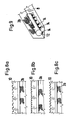
- spray electrodes (4) of the second stage (2) are shown schematically together with a tapping device.
- Metal wires, metal strips or plastic fibers coated with electrically conductive substances can be used as spray electrodes, for example.
- Each spray electrode (4) is clamped vertically in a frame (4a) belonging to the suspension device (18), on which an anvil (4b) is arranged.
- the monkey (23) is firmly connected to a rotatably mounted shaft (24).
- a lifting lever (25) is attached to the shaft (24) and is pivoted (26) is connected to a pull rod (27).
- the pull rod (27) is arranged to be vertically displaceable by the bearing (28). If the pull rod (27) is now moved in the direction of the arrow, the monkey (23) strikes the anvil (4b).
- FIG. 11 the housing wall (9) of the second stage (2) is shown together with a knocking device.
- the knocking device corresponds to that knocking device which is shown in FIG. If the pull rod (27) is moved in the direction of the arrow, the drop hammer (23) strikes the anvil (9a), which is arranged directly on the housing wall (9).
- FIG. 12 shows the top view of the knocking device shown in FIG. 11.
- the shaft (24) is shown enlarged in FIG.
- the drop hammer (23) is welded to the shaft (24).
- the lifting lever (25) is also welded to the shaft (24).
- the head device shown in FIGS. 10 to 12 is only given as an example. Other knocking devices can also be used.
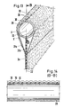
- the tube (29) which is connected to the precipitation electrode (3b).
- the tube (29) On its side facing away from the precipitation electrode (3b), the tube (29) has holes (30) in the plane (32) of the precipitation electrode (3b) through which the liquid exits from the inside of the tube to the outside.
- the tube (29) is additionally connected to the precipitation electrode (3b) via the plates (31a) and (31b).
- the plates (31a) and (31b) are connected tangentially over the entire length of the tube (29) to the tube (29) at the points (X) and (X ').
- the liquid escaping through the bores (30) runs on the outer wall of the tube (29) to the plates (31a) and (31b), whereby a Forms liquid film with a constant thickness.
- the liquid reaches the surface of the precipitation electrode (3b) directly via the plates (31a) and (31b) and flows downwards.
- the amount of exhaust gas from a sintered belt is 400,000 Nm3 / h, the exhaust gas having a temperature of 120 ° C, a dew point of 40 ° C and a dust content of 1 g / Nm3.
- the duration of the treatment time in the first stage (1) of the multi-field separator is 6.2 s
- the treatment time in the second stage (2) of the multi-field separator is 1.8 s
- the precipitation area of the precipitation electrodes (3b) of the second stage (2) is 23% of the total precipitation area of the separator.
- the throughput for the liquid for wetting the precipitation electrodes (3b) is 300 m3 / h.
- a residual dusty content after treatment in the range of the first stage (1) was 135 mg / Nm3 and in the second stage (2) of 21 mg / Nm3 measured.
- the emission values for dusty inorganic substances were below the second stage (2) for class I (Cd, Hg, etc.) below 0.2 mg / Nm3, for class II (As, Ni, etc.) below 1.0 mg / Nm3 and for class III (Pb, F, Sn, etc.) below 5.0 mg / Nm3 (classification of the dust-like inorganic substances according to TA-Luft from 27.02.1986).
- the limit values for vaporous or gaseous inorganic substances - especially for SO2 with 500 mg / Nm3 - were not exceeded in the test.
- the temperature drop in the area of the wetted precipitation electrodes (3b) was approx. 25 ° C, causing the gas temperature to drop to 95 ° C and the dew point to be raised to 44 ° C.
- the downstream fan increased the gas temperature by 24 ° C, which raised it to 119 ° C again.
- the gas therefore had one Gas inlet temperature at the chimney base of 119 ° C.
- the relatively slight cooling of the exhaust gas which was brought about in accordance with the invention in the second stage (2), achieved energy savings of approximately 120 kW for the 3 MW blower used at a gas inlet temperature of 95 ° C. and a dew point of 44 ° C. .
Landscapes
- Engineering & Computer Science (AREA)
- Mechanical Engineering (AREA)
- Electrostatic Separation (AREA)
- Treating Waste Gases (AREA)
Priority Applications (1)
| Application Number | Priority Date | Filing Date | Title |
|---|---|---|---|
| AT90202257T ATE102852T1 (de) | 1989-08-31 | 1990-08-22 | Verfahren und vorrichtung zur elektrostatischen reinigung staub- und schadstoffhaltiger abgase in mehrfeldrigen abscheidern. |
Applications Claiming Priority (6)
| Application Number | Priority Date | Filing Date | Title |
|---|---|---|---|
| DE3928808 | 1989-08-31 | ||
| DE3928808A DE3928808C1 (en) | 1989-08-31 | 1989-08-31 | Treating chemical pollutants - by passage of waste gas through multiple passages between collector plates |
| DE19904004357 DE4004357C1 (en) | 1989-08-31 | 1990-02-13 | Gas electrostatic cleaning system - has linkage driven hammer operating against striker at bottom edge of screen |
| DE4004357 | 1990-02-13 | ||
| DE4023723 | 1990-07-26 | ||
| DE19904023723 DE4023723C1 (fr) | 1989-08-31 | 1990-07-26 |
Publications (2)
| Publication Number | Publication Date |
|---|---|
| EP0415486A1 true EP0415486A1 (fr) | 1991-03-06 |
| EP0415486B1 EP0415486B1 (fr) | 1994-03-16 |
Family
ID=27200108
Family Applications (1)
| Application Number | Title | Priority Date | Filing Date |
|---|---|---|---|
| EP90202257A Expired - Lifetime EP0415486B1 (fr) | 1989-08-31 | 1990-08-22 | Procédé et appareil pour la purification électrostatique d'effluents de gaz nocifs et poussiéreux dans des séparateurs à plusieurs champs |
Country Status (6)
| Country | Link |
|---|---|
| US (1) | US5137546A (fr) |
| EP (1) | EP0415486B1 (fr) |
| JP (1) | JPH03165848A (fr) |
| KR (1) | KR910004255A (fr) |
| AU (1) | AU624527B2 (fr) |
| DE (1) | DE59004994D1 (fr) |
Cited By (9)
| Publication number | Priority date | Publication date | Assignee | Title |
|---|---|---|---|---|
| WO2007140882A1 (fr) * | 2006-06-07 | 2007-12-13 | Alstom Technology Ltd | Précipitateur électrostatique humide |
| WO2011054878A1 (fr) * | 2009-11-05 | 2011-05-12 | Omega Thermo Products Llc | Panneau et utilisation d'un tel panneau dans un dispositif pour nettoyer des gaz par extraction d'impuretés à partir de ceux-ci |
| CN103551250A (zh) * | 2013-11-05 | 2014-02-05 | 福建龙净环保股份有限公司 | 一种电除尘器及其振打方法 |
| CN105396694A (zh) * | 2015-12-31 | 2016-03-16 | 哈尔滨众维豪环保科技有限公司 | 一种干湿式一体电除尘装置 |
| CN106179742A (zh) * | 2016-08-30 | 2016-12-07 | 艾尼科环保技术(安徽)有限公司 | 一种带蒸发冷却段的干湿复合型静电除尘器 |
| CN106955789A (zh) * | 2017-05-25 | 2017-07-18 | 安徽意义环保设备有限公司 | 一种组合式自动清灰的电除尘器 |
| CN106975569A (zh) * | 2017-02-23 | 2017-07-25 | 合肥三邦环保科技有限公司 | 一种静电式油烟净化装置 |
| CN106975571A (zh) * | 2017-05-25 | 2017-07-25 | 安徽意义环保设备有限公司 | 一种可以自动清灰的电除尘器 |
| CN106975572A (zh) * | 2017-05-25 | 2017-07-25 | 安徽意义环保设备有限公司 | 一种电除尘器阴极吊挂系统 |
Families Citing this family (58)
| Publication number | Priority date | Publication date | Assignee | Title |
|---|---|---|---|---|
| DE4200343C2 (de) * | 1992-01-09 | 1993-11-11 | Metallgesellschaft Ag | Elektrostatischer Abscheider |
| DE4233303C1 (de) * | 1992-10-03 | 1994-01-20 | Metallgesellschaft Ag | Verfahren zur Abtrennung von Dioxinen und Furanen aus Abgasen von Verbrennungsanlagen |
| DK0703005T3 (da) * | 1994-09-21 | 2000-05-08 | Allrad No 28 Pty Ltd | En elektrostatisk udfælder |
| AT406024B (de) * | 1995-05-02 | 2000-01-25 | Scheuch Alois Gmbh | Anlage zur elektrostatischen reinigung von staubhaltigem abgas |
| US5871703A (en) * | 1996-10-09 | 1999-02-16 | Zero Emissions Technology Inc. | Barrier discharge conversion of SO2 and NOx to acids |
| AU4813497A (en) * | 1996-10-09 | 1998-05-05 | Francis R. Alix | Barrier discharge conversion of so2 and nox to acids |
| US6132692A (en) * | 1996-10-09 | 2000-10-17 | Powerspan Corp. | Barrier discharge conversion of SO2 and NOx to acids |
| US7022296B1 (en) | 1997-07-10 | 2006-04-04 | University Of Cincinnati | Method for treating flue gas |
| TW494021B (en) * | 1997-12-02 | 2002-07-11 | Supar Technology Co Ltd | Method for removing oil mist from electrostatic oil mist collector and device therefore |
| US6461870B2 (en) * | 1998-05-06 | 2002-10-08 | Isotechnika Inc. | 13C glucose breath test for the diagnosis of diabetic indications and monitoring glycemic control |
| ES2284274T3 (es) | 1998-06-17 | 2007-11-01 | Ohio University | Precipitador electrostatico con membrana. |
| US7318856B2 (en) | 1998-11-05 | 2008-01-15 | Sharper Image Corporation | Air treatment apparatus having an electrode extending along an axis which is substantially perpendicular to an air flow path |
| US20050210902A1 (en) | 2004-02-18 | 2005-09-29 | Sharper Image Corporation | Electro-kinetic air transporter and/or conditioner devices with features for cleaning emitter electrodes |
| US7220295B2 (en) | 2003-05-14 | 2007-05-22 | Sharper Image Corporation | Electrode self-cleaning mechanisms with anti-arc guard for electro-kinetic air transporter-conditioner devices |
| US20030206837A1 (en) | 1998-11-05 | 2003-11-06 | Taylor Charles E. | Electro-kinetic air transporter and conditioner device with enhanced maintenance features and enhanced anti-microorganism capability |
| US6176977B1 (en) | 1998-11-05 | 2001-01-23 | Sharper Image Corporation | Electro-kinetic air transporter-conditioner |
| US6544485B1 (en) | 2001-01-29 | 2003-04-08 | Sharper Image Corporation | Electro-kinetic device with enhanced anti-microorganism capability |
| US7695690B2 (en) | 1998-11-05 | 2010-04-13 | Tessera, Inc. | Air treatment apparatus having multiple downstream electrodes |
| US6398848B1 (en) * | 1999-04-26 | 2002-06-04 | American Electric Power Service | Method of separating a low density fly ash fraction from an overall group of fly ash |
| US6302945B1 (en) * | 1999-06-11 | 2001-10-16 | Electric Power Research Institute, Incorporated | Electrostatic precipitator for removing SO2 |
| US6488740B1 (en) * | 2000-03-01 | 2002-12-03 | Electric Power Research Institute, Inc. | Apparatus and method for decreasing contaminants present in a flue gas stream |
| US6432280B1 (en) | 2000-10-23 | 2002-08-13 | Pioneer Industrial Technologies, Inc. | Pollution control device |
| AU2003233515A1 (en) * | 2002-05-09 | 2003-11-11 | Ohio University | Membrane laminar wet electrostatic precipitator |
| US6899745B2 (en) * | 2002-10-08 | 2005-05-31 | Kaz, Inc. | Electrostatic air cleaner |
| US6955075B2 (en) * | 2002-11-04 | 2005-10-18 | Westinghouse Savannah River Co., Llc | Portable liquid collection electrostatic precipitator |
| US7405672B2 (en) | 2003-04-09 | 2008-07-29 | Sharper Image Corp. | Air treatment device having a sensor |
| FI121410B (fi) * | 2003-06-24 | 2010-11-15 | Alstom Technology Ltd | Menetelmä sähkösuodattimen puhdistamiseksi suodatustoiminnan aikana ja sähkösuodatin |
| US20050051420A1 (en) | 2003-09-05 | 2005-03-10 | Sharper Image Corporation | Electro-kinetic air transporter and conditioner devices with insulated driver electrodes |
| US7077890B2 (en) | 2003-09-05 | 2006-07-18 | Sharper Image Corporation | Electrostatic precipitators with insulated driver electrodes |
| US7906080B1 (en) | 2003-09-05 | 2011-03-15 | Sharper Image Acquisition Llc | Air treatment apparatus having a liquid holder and a bipolar ionization device |
| US7517503B2 (en) | 2004-03-02 | 2009-04-14 | Sharper Image Acquisition Llc | Electro-kinetic air transporter and conditioner devices including pin-ring electrode configurations with driver electrode |
| US7724492B2 (en) | 2003-09-05 | 2010-05-25 | Tessera, Inc. | Emitter electrode having a strip shape |
| US7767169B2 (en) | 2003-12-11 | 2010-08-03 | Sharper Image Acquisition Llc | Electro-kinetic air transporter-conditioner system and method to oxidize volatile organic compounds |
| US7638104B2 (en) | 2004-03-02 | 2009-12-29 | Sharper Image Acquisition Llc | Air conditioner device including pin-ring electrode configurations with driver electrode |
| US20060016333A1 (en) | 2004-07-23 | 2006-01-26 | Sharper Image Corporation | Air conditioner device with removable driver electrodes |
| US7285155B2 (en) | 2004-07-23 | 2007-10-23 | Taylor Charles E | Air conditioner device with enhanced ion output production features |
| US7311762B2 (en) | 2004-07-23 | 2007-12-25 | Sharper Image Corporation | Air conditioner device with a removable driver electrode |
| WO2006094174A2 (fr) * | 2005-03-02 | 2006-09-08 | Eisenmann Corporation | Electrofiltre humide double flux |
| US7297182B2 (en) * | 2005-03-02 | 2007-11-20 | Eisenmann Corporation | Wet electrostatic precipitator for treating oxidized biomass effluent |
| WO2006113639A2 (fr) * | 2005-04-15 | 2006-10-26 | Eisenmann Corporation | Procede et appareil de desulfuration de gaz de combustion |
| US8043412B2 (en) * | 2005-06-16 | 2011-10-25 | Savannah River Nuclear Solutions, Llc | High volume, multiple use, portable precipitator |
| WO2007008587A2 (fr) * | 2005-07-08 | 2007-01-18 | Eisenmann Corporation | Methode et appareil d'elimination de particulats et d'epuration de vapeurs indesirables d'un flux circulant de gaz |
| WO2007067626A2 (fr) * | 2005-12-06 | 2007-06-14 | Eisenmann Corporation | Reacteur d'oxydation a film liquide electrostatique humide et procede d'elimination de nox, sox, mercure, gouttelettes d’acide, metaux lourds et particules de cendres d’un gaz en mouvement |
| US7833322B2 (en) | 2006-02-28 | 2010-11-16 | Sharper Image Acquisition Llc | Air treatment apparatus having a voltage control device responsive to current sensing |
| CN102006939A (zh) * | 2008-02-11 | 2011-04-06 | 亚达帕丽·空达拉·姚 | 用于收集作业中产生的杂质的真空泵吸滤装置 |
| US7632341B2 (en) * | 2008-03-27 | 2009-12-15 | Babcock & Wilcox Power Generation Group, Inc. | Hybrid wet electrostatic precipitator |
| DE102008046414A1 (de) * | 2008-09-04 | 2010-03-18 | Eisenmann Anlagenbau Gmbh & Co. Kg | Vorrichtung zum Abscheiden von Lack-Overspray |
| TWI359048B (en) * | 2009-09-10 | 2012-03-01 | Univ Nat Chiao Tung | Wet electrostatic precipitator with pulse jet clea |
| US8323386B2 (en) * | 2009-10-16 | 2012-12-04 | Midwest Research Institute, Inc. | Apparatus and method for electrostatic particulate collector |
| DE102010007479B3 (de) * | 2010-02-09 | 2011-06-22 | EISENMANN Anlagenbau GmbH & Co. KG, 71032 | Anlage zum Beschichten von Gegenständen |
| CN101816975A (zh) * | 2010-05-17 | 2010-09-01 | 山东电力研究院 | 干湿混合电除尘器 |
| JP5800717B2 (ja) * | 2012-01-05 | 2015-10-28 | 三菱電機株式会社 | ミスト状物質除去装置 |
| KR200479771Y1 (ko) * | 2014-05-22 | 2016-03-07 | 오동진 | 집진 장치용 집진판 |
| CN104190540A (zh) * | 2014-08-15 | 2014-12-10 | 浙江诸暨利达环保设备有限公司 | 一种干湿混合电除尘装置 |
| US10799884B2 (en) * | 2014-10-16 | 2020-10-13 | Ohio University | Wet electrostatic precipitator and method of treating an exhaust |
| CN105689132B (zh) * | 2016-03-11 | 2017-06-06 | 浙江信雅达环保工程有限公司 | 干湿复合电除尘器 |
| KR102047762B1 (ko) * | 2018-02-05 | 2019-11-25 | 엘지전자 주식회사 | 전기 집진 필터 및 이를 포함하는 전기 집진 장치 |
| CN116618180B (zh) * | 2023-07-20 | 2023-09-22 | 江苏中纺联针织有限公司 | 一种纺织粉尘收集装置 |
Citations (8)
| Publication number | Priority date | Publication date | Assignee | Title |
|---|---|---|---|---|
| US1968334A (en) * | 1932-07-13 | 1934-07-31 | Research Corp | Water film precipitator |
| GB609386A (en) * | 1944-08-29 | 1948-09-30 | Smidth & Co As F L | Improvements in and relating to electrostatic dust-separating filters |
| FR1139151A (fr) * | 1955-12-29 | 1957-06-26 | Cfcmug | Perfectionnements aux précipitateurs électrostatiques humides |
| CH362682A (de) * | 1958-10-04 | 1962-06-30 | Gema Ag Apparatebau Und Stanze | Elektrofilter, insbesondere zum Reinigen von Rauchgasen |
| GB988350A (en) * | 1964-03-23 | 1965-04-07 | Onoda Cement Co Ltd | An apparatus and a method for the electrical precipitation of dust |
| FR1487268A (fr) * | 1966-07-22 | 1967-06-30 | Metallgesellschaft Ag | Procédé pour augmenter le taux d'ensemble d'épuration, notamment dans une installation de dépoussiérage de gaz de frittage |
| DE1926752A1 (de) * | 1968-07-15 | 1970-01-22 | Metallgesellschaft Ag | Vorrichtung zum Abreinigen von Spruehelektroden |
| EP0076627A1 (fr) * | 1981-10-07 | 1983-04-13 | Dresser Industries,Inc. | Précipitateurs électrostatiques humides |
Family Cites Families (9)
| Publication number | Priority date | Publication date | Assignee | Title |
|---|---|---|---|---|
| US1766422A (en) * | 1927-11-28 | 1930-06-24 | Research Corp | Method and apparatus for electrical precipitation |
| DE565152C (de) * | 1929-07-02 | 1933-10-17 | Siemens Schuckertwerke Akt Ges | Verfahren zur Saeuberung der Spruehelektroden von elektrischen Gasreinigern |
| BE621783A (fr) * | 1961-09-27 | |||
| US4181509A (en) * | 1975-06-19 | 1980-01-01 | Envirotech Corporation | Flow preconditioner for electrostatic precipitator |
| US4189308A (en) * | 1978-10-31 | 1980-02-19 | Research-Cottrell, Inc. | High voltage wetted parallel plate collecting electrode arrangement for an electrostatic precipitator |
| JPS5561946A (en) * | 1978-11-01 | 1980-05-10 | Hitachi Ltd | Anti-corrosive method for wet-type electric dust collector |
| SU806069A1 (ru) * | 1979-01-03 | 1981-02-23 | Всесоюзный Научно-Исследовательскийи Проектный Институт По Очистке Tex-Нологических Газов, Сточных Вод Ииспользованию Вторичных Энергоресур-Cob Предприятий Черной Металлургии"Внипичерметэнергоочистка" | Электрофильтр дл мокрой очисткигАзА |
| CA1159773A (fr) * | 1981-09-30 | 1984-01-03 | George Drzewiecki | Separateur par voie humide avec plaques hexagonales de captage imbriquees, dispositif magnetique d'alignement et secoueur de decolmatage |
| CH673411A5 (fr) * | 1987-11-27 | 1990-03-15 | Bbc Brown Boveri & Cie |
-
1990
- 1990-08-22 EP EP90202257A patent/EP0415486B1/fr not_active Expired - Lifetime
- 1990-08-22 DE DE90202257T patent/DE59004994D1/de not_active Expired - Fee Related
- 1990-08-30 AU AU62006/90A patent/AU624527B2/en not_active Ceased
- 1990-08-30 KR KR1019900013814A patent/KR910004255A/ko not_active Withdrawn
- 1990-08-31 US US07/578,021 patent/US5137546A/en not_active Expired - Fee Related
- 1990-08-31 JP JP2230457A patent/JPH03165848A/ja active Pending
Patent Citations (8)
| Publication number | Priority date | Publication date | Assignee | Title |
|---|---|---|---|---|
| US1968334A (en) * | 1932-07-13 | 1934-07-31 | Research Corp | Water film precipitator |
| GB609386A (en) * | 1944-08-29 | 1948-09-30 | Smidth & Co As F L | Improvements in and relating to electrostatic dust-separating filters |
| FR1139151A (fr) * | 1955-12-29 | 1957-06-26 | Cfcmug | Perfectionnements aux précipitateurs électrostatiques humides |
| CH362682A (de) * | 1958-10-04 | 1962-06-30 | Gema Ag Apparatebau Und Stanze | Elektrofilter, insbesondere zum Reinigen von Rauchgasen |
| GB988350A (en) * | 1964-03-23 | 1965-04-07 | Onoda Cement Co Ltd | An apparatus and a method for the electrical precipitation of dust |
| FR1487268A (fr) * | 1966-07-22 | 1967-06-30 | Metallgesellschaft Ag | Procédé pour augmenter le taux d'ensemble d'épuration, notamment dans une installation de dépoussiérage de gaz de frittage |
| DE1926752A1 (de) * | 1968-07-15 | 1970-01-22 | Metallgesellschaft Ag | Vorrichtung zum Abreinigen von Spruehelektroden |
| EP0076627A1 (fr) * | 1981-10-07 | 1983-04-13 | Dresser Industries,Inc. | Précipitateurs électrostatiques humides |
Non-Patent Citations (1)
| Title |
|---|
| PATENT ABSTRACTS OF JAPAN vol. 5, no. 35 (C-46)(707) 05 März 1981, & JP-A-55 159857 (HITACHI) 12 Dezember 1980, * |
Cited By (12)
| Publication number | Priority date | Publication date | Assignee | Title |
|---|---|---|---|---|
| WO2007140882A1 (fr) * | 2006-06-07 | 2007-12-13 | Alstom Technology Ltd | Précipitateur électrostatique humide |
| US8088198B2 (en) | 2006-06-07 | 2012-01-03 | Alstom Technology Ltd | Wet electrostatic precipitator |
| WO2011054878A1 (fr) * | 2009-11-05 | 2011-05-12 | Omega Thermo Products Llc | Panneau et utilisation d'un tel panneau dans un dispositif pour nettoyer des gaz par extraction d'impuretés à partir de ceux-ci |
| US8303686B2 (en) | 2009-11-05 | 2012-11-06 | Omega Thermo Products Llc | Panel and use of such a panel in a device for cleaning gases by removing impurities therefrom |
| CN103551250A (zh) * | 2013-11-05 | 2014-02-05 | 福建龙净环保股份有限公司 | 一种电除尘器及其振打方法 |
| CN105396694A (zh) * | 2015-12-31 | 2016-03-16 | 哈尔滨众维豪环保科技有限公司 | 一种干湿式一体电除尘装置 |
| CN106179742A (zh) * | 2016-08-30 | 2016-12-07 | 艾尼科环保技术(安徽)有限公司 | 一种带蒸发冷却段的干湿复合型静电除尘器 |
| CN106975569A (zh) * | 2017-02-23 | 2017-07-25 | 合肥三邦环保科技有限公司 | 一种静电式油烟净化装置 |
| CN106975569B (zh) * | 2017-02-23 | 2018-07-17 | 合肥三邦环保科技有限公司 | 一种静电式油烟净化装置 |
| CN106955789A (zh) * | 2017-05-25 | 2017-07-18 | 安徽意义环保设备有限公司 | 一种组合式自动清灰的电除尘器 |
| CN106975571A (zh) * | 2017-05-25 | 2017-07-25 | 安徽意义环保设备有限公司 | 一种可以自动清灰的电除尘器 |
| CN106975572A (zh) * | 2017-05-25 | 2017-07-25 | 安徽意义环保设备有限公司 | 一种电除尘器阴极吊挂系统 |
Also Published As
| Publication number | Publication date |
|---|---|
| JPH03165848A (ja) | 1991-07-17 |
| US5137546A (en) | 1992-08-11 |
| AU624527B2 (en) | 1992-06-11 |
| DE59004994D1 (de) | 1994-04-21 |
| AU6200690A (en) | 1991-03-07 |
| EP0415486B1 (fr) | 1994-03-16 |
| KR910004255A (ko) | 1991-03-28 |
Similar Documents
| Publication | Publication Date | Title |
|---|---|---|
| EP0415486B1 (fr) | Procédé et appareil pour la purification électrostatique d'effluents de gaz nocifs et poussiéreux dans des séparateurs à plusieurs champs | |
| EP0461695B1 (fr) | Procédé et appareil pour la purification d'effluents de gaz poussiéreux et nocifs | |
| DE3122515C2 (de) | Elektrostatische Filteranordnung | |
| DE2626789A1 (de) | Verfahren zur entfernung von partikeln aus einem gasstrom | |
| DE2320694A1 (de) | Elektrostatischer nassabscheider | |
| EP2343130A1 (fr) | Dispositif de séparation du brouillard de peinture excédentaire | |
| CH638107A5 (de) | Vorrichtung und verfahren zum absorbieren von verunreinigungen in abgasen. | |
| WO2004033104A1 (fr) | Ionisateur et utilisation dans une installation d'epuration de gaz d'echappement pour gaz humides condenses et/ou charges de gouttelettes | |
| AT406024B (de) | Anlage zur elektrostatischen reinigung von staubhaltigem abgas | |
| DE4018488C1 (en) | Removing dust and hazardous materials from waste gases - by sepg. dust in dry multi-cyclone stage, and wet electrostatic precipitator stage | |
| CH636778A5 (de) | Verfahren und vorrichtung zur abscheidung von feinstaeuben und aerosolen aus einem gasstrom. | |
| DE3928808C1 (en) | Treating chemical pollutants - by passage of waste gas through multiple passages between collector plates | |
| DE3307999A1 (de) | Verfahren und anlage zur verminderung von schadstoffen in gasen | |
| DE1239277B (de) | Verfahren zur Abscheidung von Nebeln und Feststoffen aus Gasen mittels Roehren-Nassentstaubern | |
| EP0545943B1 (fr) | Procede et systeme de separation de particules solides et/ou liquides et/ou gaseaux contenus dans un courant de gas | |
| DE4004357C1 (en) | Gas electrostatic cleaning system - has linkage driven hammer operating against striker at bottom edge of screen | |
| DE2235531A1 (de) | Verfahren und einrichtung zum entfernen von fremdstoffteilchen u. dgl. aus einem gasstrom | |
| DE19651857C1 (de) | Vorrichtung zur Abscheidung von Feststoffen aus staubbeladenen Abgasen, insbesondere von Verbrennungsanlagen | |
| DE102008046410B4 (de) | Vorrichtung zum Abscheiden von Lack-Overspray | |
| DE2820650B2 (de) | Vorrichtung zum Austausch eines kernförmigen die Füllung eines Filters bildenden Filtermaterials einer Gasreinigungsanlage | |
| DE2933019A1 (de) | Verfahren und vorrichtung zum abreinigen der rauchgase einer aufbereitungsanlage fuer bituminoeses mischgut | |
| EP0447436A1 (fr) | Procede de separation electrostatique de particules solides et d'aerosols contenus dans des gaz | |
| DE2745363A1 (de) | Elektrostatischer staubabscheider | |
| DE102006004723B4 (de) | Vorrichtung zum Abscheiden von Flüssigkeitstropfen aus Gasströmen sowie Anordnung aus dieser Vorrichtung und einer zweiten Vorrichtung zum Abscheiden von Flüssigkeitstropfen aus Gasströmen | |
| CH674950A5 (fr) |
Legal Events
| Date | Code | Title | Description |
|---|---|---|---|
| PUAI | Public reference made under article 153(3) epc to a published international application that has entered the european phase |
Free format text: ORIGINAL CODE: 0009012 |
|
| 17P | Request for examination filed |
Effective date: 19901222 |
|
| AK | Designated contracting states |
Kind code of ref document: A1 Designated state(s): AT DE FR GB IT LU NL SE |
|
| 17Q | First examination report despatched |
Effective date: 19921006 |
|
| GRAA | (expected) grant |
Free format text: ORIGINAL CODE: 0009210 |
|
| AK | Designated contracting states |
Kind code of ref document: B1 Designated state(s): AT DE FR GB IT LU NL SE |
|
| REF | Corresponds to: |
Ref document number: 102852 Country of ref document: AT Date of ref document: 19940415 Kind code of ref document: T |
|
| GBT | Gb: translation of ep patent filed (gb section 77(6)(a)/1977) |
Effective date: 19940315 |
|
| REF | Corresponds to: |
Ref document number: 59004994 Country of ref document: DE Date of ref document: 19940421 |
|
| ET | Fr: translation filed | ||
| ITF | It: translation for a ep patent filed | ||
| PGFP | Annual fee paid to national office [announced via postgrant information from national office to epo] |
Ref country code: AT Payment date: 19940617 Year of fee payment: 5 |
|
| PGFP | Annual fee paid to national office [announced via postgrant information from national office to epo] |
Ref country code: SE Payment date: 19940621 Year of fee payment: 5 |
|
| PGFP | Annual fee paid to national office [announced via postgrant information from national office to epo] |
Ref country code: FR Payment date: 19940624 Year of fee payment: 5 |
|
| PGFP | Annual fee paid to national office [announced via postgrant information from national office to epo] |
Ref country code: LU Payment date: 19940801 Year of fee payment: 5 |
|
| PGFP | Annual fee paid to national office [announced via postgrant information from national office to epo] |
Ref country code: GB Payment date: 19940811 Year of fee payment: 5 |
|
| PGFP | Annual fee paid to national office [announced via postgrant information from national office to epo] |
Ref country code: NL Payment date: 19940831 Year of fee payment: 5 |
|
| PLBE | No opposition filed within time limit |
Free format text: ORIGINAL CODE: 0009261 |
|
| STAA | Information on the status of an ep patent application or granted ep patent |
Free format text: STATUS: NO OPPOSITION FILED WITHIN TIME LIMIT |
|
| EAL | Se: european patent in force in sweden |
Ref document number: 90202257.3 |
|
| 26N | No opposition filed | ||
| PG25 | Lapsed in a contracting state [announced via postgrant information from national office to epo] |
Ref country code: LU Free format text: LAPSE BECAUSE OF NON-PAYMENT OF DUE FEES Effective date: 19950822 Ref country code: GB Effective date: 19950822 Ref country code: AT Effective date: 19950822 |
|
| PG25 | Lapsed in a contracting state [announced via postgrant information from national office to epo] |
Ref country code: SE Effective date: 19950823 |
|
| PG25 | Lapsed in a contracting state [announced via postgrant information from national office to epo] |
Ref country code: NL Effective date: 19960301 |
|
| GBPC | Gb: european patent ceased through non-payment of renewal fee |
Effective date: 19950822 |
|
| PG25 | Lapsed in a contracting state [announced via postgrant information from national office to epo] |
Ref country code: FR Effective date: 19960430 |
|
| NLV4 | Nl: lapsed or anulled due to non-payment of the annual fee |
Effective date: 19960301 |
|
| EUG | Se: european patent has lapsed |
Ref document number: 90202257.3 |
|
| REG | Reference to a national code |
Ref country code: FR Ref legal event code: ST |
|
| PGFP | Annual fee paid to national office [announced via postgrant information from national office to epo] |
Ref country code: DE Payment date: 20020809 Year of fee payment: 13 |
|
| PG25 | Lapsed in a contracting state [announced via postgrant information from national office to epo] |
Ref country code: DE Free format text: LAPSE BECAUSE OF NON-PAYMENT OF DUE FEES Effective date: 20040302 |
|
| PG25 | Lapsed in a contracting state [announced via postgrant information from national office to epo] |
Ref country code: IT Free format text: LAPSE BECAUSE OF NON-PAYMENT OF DUE FEES Effective date: 20050822 |