EP0415543A2 - Magneto-optische Platteneinheit mit halber Dicke - Google Patents
Magneto-optische Platteneinheit mit halber Dicke Download PDFInfo
- Publication number
- EP0415543A2 EP0415543A2 EP90307980A EP90307980A EP0415543A2 EP 0415543 A2 EP0415543 A2 EP 0415543A2 EP 90307980 A EP90307980 A EP 90307980A EP 90307980 A EP90307980 A EP 90307980A EP 0415543 A2 EP0415543 A2 EP 0415543A2
- Authority
- EP
- European Patent Office
- Prior art keywords
- optical disk
- cartridge
- drive
- baseplate
- rotary arm
- Prior art date
- Legal status (The legal status is an assumption and is not a legal conclusion. Google has not performed a legal analysis and makes no representation as to the accuracy of the status listed.)
- Granted
Links
- 230000003287 optical effect Effects 0.000 claims abstract description 117
- 230000007246 mechanism Effects 0.000 claims abstract description 45
- 230000033001 locomotion Effects 0.000 claims description 13
- 230000008878 coupling Effects 0.000 claims description 5
- 238000010168 coupling process Methods 0.000 claims description 5
- 238000005859 coupling reaction Methods 0.000 claims description 5
- 239000002184 metal Substances 0.000 claims 1
- 230000005291 magnetic effect Effects 0.000 description 26
- 230000020347 spindle assembly Effects 0.000 description 12
- 230000000712 assembly Effects 0.000 description 11
- 238000000429 assembly Methods 0.000 description 11
- 230000004044 response Effects 0.000 description 7
- 230000005355 Hall effect Effects 0.000 description 6
- 230000006870 function Effects 0.000 description 4
- 230000010287 polarization Effects 0.000 description 4
- 238000005452 bending Methods 0.000 description 3
- 239000011248 coating agent Substances 0.000 description 3
- 238000000576 coating method Methods 0.000 description 3
- 230000000694 effects Effects 0.000 description 3
- 230000005294 ferromagnetic effect Effects 0.000 description 3
- 239000004593 Epoxy Substances 0.000 description 2
- 230000005540 biological transmission Effects 0.000 description 2
- 238000013500 data storage Methods 0.000 description 2
- 238000005516 engineering process Methods 0.000 description 2
- 238000010438 heat treatment Methods 0.000 description 2
- 230000005693 optoelectronics Effects 0.000 description 2
- 239000004033 plastic Substances 0.000 description 2
- 238000007493 shaping process Methods 0.000 description 2
- 230000005374 Kerr effect Effects 0.000 description 1
- FYYHWMGAXLPEAU-UHFFFAOYSA-N Magnesium Chemical compound [Mg] FYYHWMGAXLPEAU-UHFFFAOYSA-N 0.000 description 1
- 229910000639 Spring steel Inorganic materials 0.000 description 1
- 230000001133 acceleration Effects 0.000 description 1
- 230000009471 action Effects 0.000 description 1
- 239000000853 adhesive Substances 0.000 description 1
- 230000001070 adhesive effect Effects 0.000 description 1
- XAGFODPZIPBFFR-UHFFFAOYSA-N aluminium Chemical compound [Al] XAGFODPZIPBFFR-UHFFFAOYSA-N 0.000 description 1
- 229910052782 aluminium Inorganic materials 0.000 description 1
- 230000000295 complement effect Effects 0.000 description 1
- 238000001816 cooling Methods 0.000 description 1
- 230000001066 destructive effect Effects 0.000 description 1
- 238000010586 diagram Methods 0.000 description 1
- 229910052749 magnesium Inorganic materials 0.000 description 1
- 239000011777 magnesium Substances 0.000 description 1
- 238000000034 method Methods 0.000 description 1
- 239000002991 molded plastic Substances 0.000 description 1
- 230000010363 phase shift Effects 0.000 description 1
- 229920000642 polymer Polymers 0.000 description 1
- 230000001902 propagating effect Effects 0.000 description 1
- 230000000284 resting effect Effects 0.000 description 1
- 125000006850 spacer group Chemical group 0.000 description 1
- 238000009423 ventilation Methods 0.000 description 1
- 230000000007 visual effect Effects 0.000 description 1
- 238000004804 winding Methods 0.000 description 1
Images




Classifications
-
- G—PHYSICS
- G11—INFORMATION STORAGE
- G11B—INFORMATION STORAGE BASED ON RELATIVE MOVEMENT BETWEEN RECORD CARRIER AND TRANSDUCER
- G11B17/00—Guiding record carriers not specifically of filamentary or web form, or of supports therefor
- G11B17/02—Details
- G11B17/04—Feeding or guiding single record carrier to or from transducer unit
- G11B17/041—Feeding or guiding single record carrier to or from transducer unit specially adapted for discs contained within cartridges
- G11B17/043—Direct insertion, i.e. without external loading means
- G11B17/0436—Direct insertion, i.e. without external loading means with opening mechanism of the cartridge shutter
-
- G—PHYSICS
- G11—INFORMATION STORAGE
- G11B—INFORMATION STORAGE BASED ON RELATIVE MOVEMENT BETWEEN RECORD CARRIER AND TRANSDUCER
- G11B11/00—Recording on or reproducing from the same record carrier wherein for these two operations the methods are covered by different main groups of groups G11B3/00 - G11B7/00 or by different subgroups of group G11B9/00; Record carriers therefor
- G11B11/10—Recording on or reproducing from the same record carrier wherein for these two operations the methods are covered by different main groups of groups G11B3/00 - G11B7/00 or by different subgroups of group G11B9/00; Record carriers therefor using recording by magnetic means or other means for magnetisation or demagnetisation of a record carrier, e.g. light induced spin magnetisation; Demagnetisation by thermal or stress means in the presence or not of an orienting magnetic field
- G11B11/105—Recording on or reproducing from the same record carrier wherein for these two operations the methods are covered by different main groups of groups G11B3/00 - G11B7/00 or by different subgroups of group G11B9/00; Record carriers therefor using recording by magnetic means or other means for magnetisation or demagnetisation of a record carrier, e.g. light induced spin magnetisation; Demagnetisation by thermal or stress means in the presence or not of an orienting magnetic field using a beam of light or a magnetic field for recording by change of magnetisation and a beam of light for reproducing, i.e. magneto-optical, e.g. light-induced thermomagnetic recording, spin magnetisation recording, Kerr or Faraday effect reproducing
- G11B11/10502—Recording on or reproducing from the same record carrier wherein for these two operations the methods are covered by different main groups of groups G11B3/00 - G11B7/00 or by different subgroups of group G11B9/00; Record carriers therefor using recording by magnetic means or other means for magnetisation or demagnetisation of a record carrier, e.g. light induced spin magnetisation; Demagnetisation by thermal or stress means in the presence or not of an orienting magnetic field using a beam of light or a magnetic field for recording by change of magnetisation and a beam of light for reproducing, i.e. magneto-optical, e.g. light-induced thermomagnetic recording, spin magnetisation recording, Kerr or Faraday effect reproducing characterised by the transducing operation to be executed
- G11B11/10504—Recording
-
- G—PHYSICS
- G11—INFORMATION STORAGE
- G11B—INFORMATION STORAGE BASED ON RELATIVE MOVEMENT BETWEEN RECORD CARRIER AND TRANSDUCER
- G11B11/00—Recording on or reproducing from the same record carrier wherein for these two operations the methods are covered by different main groups of groups G11B3/00 - G11B7/00 or by different subgroups of group G11B9/00; Record carriers therefor
- G11B11/10—Recording on or reproducing from the same record carrier wherein for these two operations the methods are covered by different main groups of groups G11B3/00 - G11B7/00 or by different subgroups of group G11B9/00; Record carriers therefor using recording by magnetic means or other means for magnetisation or demagnetisation of a record carrier, e.g. light induced spin magnetisation; Demagnetisation by thermal or stress means in the presence or not of an orienting magnetic field
- G11B11/105—Recording on or reproducing from the same record carrier wherein for these two operations the methods are covered by different main groups of groups G11B3/00 - G11B7/00 or by different subgroups of group G11B9/00; Record carriers therefor using recording by magnetic means or other means for magnetisation or demagnetisation of a record carrier, e.g. light induced spin magnetisation; Demagnetisation by thermal or stress means in the presence or not of an orienting magnetic field using a beam of light or a magnetic field for recording by change of magnetisation and a beam of light for reproducing, i.e. magneto-optical, e.g. light-induced thermomagnetic recording, spin magnetisation recording, Kerr or Faraday effect reproducing
- G11B11/10502—Recording on or reproducing from the same record carrier wherein for these two operations the methods are covered by different main groups of groups G11B3/00 - G11B7/00 or by different subgroups of group G11B9/00; Record carriers therefor using recording by magnetic means or other means for magnetisation or demagnetisation of a record carrier, e.g. light induced spin magnetisation; Demagnetisation by thermal or stress means in the presence or not of an orienting magnetic field using a beam of light or a magnetic field for recording by change of magnetisation and a beam of light for reproducing, i.e. magneto-optical, e.g. light-induced thermomagnetic recording, spin magnetisation recording, Kerr or Faraday effect reproducing characterised by the transducing operation to be executed
- G11B11/10517—Overwriting or erasing
-
- G—PHYSICS
- G11—INFORMATION STORAGE
- G11B—INFORMATION STORAGE BASED ON RELATIVE MOVEMENT BETWEEN RECORD CARRIER AND TRANSDUCER
- G11B11/00—Recording on or reproducing from the same record carrier wherein for these two operations the methods are covered by different main groups of groups G11B3/00 - G11B7/00 or by different subgroups of group G11B9/00; Record carriers therefor
- G11B11/10—Recording on or reproducing from the same record carrier wherein for these two operations the methods are covered by different main groups of groups G11B3/00 - G11B7/00 or by different subgroups of group G11B9/00; Record carriers therefor using recording by magnetic means or other means for magnetisation or demagnetisation of a record carrier, e.g. light induced spin magnetisation; Demagnetisation by thermal or stress means in the presence or not of an orienting magnetic field
- G11B11/105—Recording on or reproducing from the same record carrier wherein for these two operations the methods are covered by different main groups of groups G11B3/00 - G11B7/00 or by different subgroups of group G11B9/00; Record carriers therefor using recording by magnetic means or other means for magnetisation or demagnetisation of a record carrier, e.g. light induced spin magnetisation; Demagnetisation by thermal or stress means in the presence or not of an orienting magnetic field using a beam of light or a magnetic field for recording by change of magnetisation and a beam of light for reproducing, i.e. magneto-optical, e.g. light-induced thermomagnetic recording, spin magnetisation recording, Kerr or Faraday effect reproducing
- G11B11/10532—Heads
- G11B11/10534—Heads for recording by magnetising, demagnetising or transfer of magnetisation, by radiation, e.g. for thermomagnetic recording
- G11B11/10536—Heads for recording by magnetising, demagnetising or transfer of magnetisation, by radiation, e.g. for thermomagnetic recording using thermic beams, e.g. lasers
-
- G—PHYSICS
- G11—INFORMATION STORAGE
- G11B—INFORMATION STORAGE BASED ON RELATIVE MOVEMENT BETWEEN RECORD CARRIER AND TRANSDUCER
- G11B11/00—Recording on or reproducing from the same record carrier wherein for these two operations the methods are covered by different main groups of groups G11B3/00 - G11B7/00 or by different subgroups of group G11B9/00; Record carriers therefor
- G11B11/10—Recording on or reproducing from the same record carrier wherein for these two operations the methods are covered by different main groups of groups G11B3/00 - G11B7/00 or by different subgroups of group G11B9/00; Record carriers therefor using recording by magnetic means or other means for magnetisation or demagnetisation of a record carrier, e.g. light induced spin magnetisation; Demagnetisation by thermal or stress means in the presence or not of an orienting magnetic field
- G11B11/105—Recording on or reproducing from the same record carrier wherein for these two operations the methods are covered by different main groups of groups G11B3/00 - G11B7/00 or by different subgroups of group G11B9/00; Record carriers therefor using recording by magnetic means or other means for magnetisation or demagnetisation of a record carrier, e.g. light induced spin magnetisation; Demagnetisation by thermal or stress means in the presence or not of an orienting magnetic field using a beam of light or a magnetic field for recording by change of magnetisation and a beam of light for reproducing, i.e. magneto-optical, e.g. light-induced thermomagnetic recording, spin magnetisation recording, Kerr or Faraday effect reproducing
- G11B11/1055—Disposition or mounting of transducers relative to record carriers
-
- G—PHYSICS
- G11—INFORMATION STORAGE
- G11B—INFORMATION STORAGE BASED ON RELATIVE MOVEMENT BETWEEN RECORD CARRIER AND TRANSDUCER
- G11B11/00—Recording on or reproducing from the same record carrier wherein for these two operations the methods are covered by different main groups of groups G11B3/00 - G11B7/00 or by different subgroups of group G11B9/00; Record carriers therefor
- G11B11/10—Recording on or reproducing from the same record carrier wherein for these two operations the methods are covered by different main groups of groups G11B3/00 - G11B7/00 or by different subgroups of group G11B9/00; Record carriers therefor using recording by magnetic means or other means for magnetisation or demagnetisation of a record carrier, e.g. light induced spin magnetisation; Demagnetisation by thermal or stress means in the presence or not of an orienting magnetic field
- G11B11/105—Recording on or reproducing from the same record carrier wherein for these two operations the methods are covered by different main groups of groups G11B3/00 - G11B7/00 or by different subgroups of group G11B9/00; Record carriers therefor using recording by magnetic means or other means for magnetisation or demagnetisation of a record carrier, e.g. light induced spin magnetisation; Demagnetisation by thermal or stress means in the presence or not of an orienting magnetic field using a beam of light or a magnetic field for recording by change of magnetisation and a beam of light for reproducing, i.e. magneto-optical, e.g. light-induced thermomagnetic recording, spin magnetisation recording, Kerr or Faraday effect reproducing
- G11B11/1055—Disposition or mounting of transducers relative to record carriers
- G11B11/10552—Arrangements of transducers relative to each other, e.g. coupled heads, optical and magnetic head on the same base
- G11B11/10554—Arrangements of transducers relative to each other, e.g. coupled heads, optical and magnetic head on the same base the transducers being disposed on the same side of the carrier
-
- G—PHYSICS
- G11—INFORMATION STORAGE
- G11B—INFORMATION STORAGE BASED ON RELATIVE MOVEMENT BETWEEN RECORD CARRIER AND TRANSDUCER
- G11B11/00—Recording on or reproducing from the same record carrier wherein for these two operations the methods are covered by different main groups of groups G11B3/00 - G11B7/00 or by different subgroups of group G11B9/00; Record carriers therefor
- G11B11/10—Recording on or reproducing from the same record carrier wherein for these two operations the methods are covered by different main groups of groups G11B3/00 - G11B7/00 or by different subgroups of group G11B9/00; Record carriers therefor using recording by magnetic means or other means for magnetisation or demagnetisation of a record carrier, e.g. light induced spin magnetisation; Demagnetisation by thermal or stress means in the presence or not of an orienting magnetic field
- G11B11/105—Recording on or reproducing from the same record carrier wherein for these two operations the methods are covered by different main groups of groups G11B3/00 - G11B7/00 or by different subgroups of group G11B9/00; Record carriers therefor using recording by magnetic means or other means for magnetisation or demagnetisation of a record carrier, e.g. light induced spin magnetisation; Demagnetisation by thermal or stress means in the presence or not of an orienting magnetic field using a beam of light or a magnetic field for recording by change of magnetisation and a beam of light for reproducing, i.e. magneto-optical, e.g. light-induced thermomagnetic recording, spin magnetisation recording, Kerr or Faraday effect reproducing
- G11B11/1055—Disposition or mounting of transducers relative to record carriers
- G11B11/10556—Disposition or mounting of transducers relative to record carriers with provision for moving or switching or masking the transducers in or out of their operative position
- G11B11/10558—Disposition or mounting of transducers relative to record carriers with provision for moving or switching or masking the transducers in or out of their operative position in view of the loading or unloading of the carrier
-
- G—PHYSICS
- G11—INFORMATION STORAGE
- G11B—INFORMATION STORAGE BASED ON RELATIVE MOVEMENT BETWEEN RECORD CARRIER AND TRANSDUCER
- G11B11/00—Recording on or reproducing from the same record carrier wherein for these two operations the methods are covered by different main groups of groups G11B3/00 - G11B7/00 or by different subgroups of group G11B9/00; Record carriers therefor
- G11B11/10—Recording on or reproducing from the same record carrier wherein for these two operations the methods are covered by different main groups of groups G11B3/00 - G11B7/00 or by different subgroups of group G11B9/00; Record carriers therefor using recording by magnetic means or other means for magnetisation or demagnetisation of a record carrier, e.g. light induced spin magnetisation; Demagnetisation by thermal or stress means in the presence or not of an orienting magnetic field
- G11B11/105—Recording on or reproducing from the same record carrier wherein for these two operations the methods are covered by different main groups of groups G11B3/00 - G11B7/00 or by different subgroups of group G11B9/00; Record carriers therefor using recording by magnetic means or other means for magnetisation or demagnetisation of a record carrier, e.g. light induced spin magnetisation; Demagnetisation by thermal or stress means in the presence or not of an orienting magnetic field using a beam of light or a magnetic field for recording by change of magnetisation and a beam of light for reproducing, i.e. magneto-optical, e.g. light-induced thermomagnetic recording, spin magnetisation recording, Kerr or Faraday effect reproducing
- G11B11/1055—Disposition or mounting of transducers relative to record carriers
- G11B11/10556—Disposition or mounting of transducers relative to record carriers with provision for moving or switching or masking the transducers in or out of their operative position
- G11B11/10567—Mechanically moving the transducers
- G11B11/10569—Swing arm positioners
-
- G—PHYSICS
- G11—INFORMATION STORAGE
- G11B—INFORMATION STORAGE BASED ON RELATIVE MOVEMENT BETWEEN RECORD CARRIER AND TRANSDUCER
- G11B11/00—Recording on or reproducing from the same record carrier wherein for these two operations the methods are covered by different main groups of groups G11B3/00 - G11B7/00 or by different subgroups of group G11B9/00; Record carriers therefor
- G11B11/10—Recording on or reproducing from the same record carrier wherein for these two operations the methods are covered by different main groups of groups G11B3/00 - G11B7/00 or by different subgroups of group G11B9/00; Record carriers therefor using recording by magnetic means or other means for magnetisation or demagnetisation of a record carrier, e.g. light induced spin magnetisation; Demagnetisation by thermal or stress means in the presence or not of an orienting magnetic field
- G11B11/105—Recording on or reproducing from the same record carrier wherein for these two operations the methods are covered by different main groups of groups G11B3/00 - G11B7/00 or by different subgroups of group G11B9/00; Record carriers therefor using recording by magnetic means or other means for magnetisation or demagnetisation of a record carrier, e.g. light induced spin magnetisation; Demagnetisation by thermal or stress means in the presence or not of an orienting magnetic field using a beam of light or a magnetic field for recording by change of magnetisation and a beam of light for reproducing, i.e. magneto-optical, e.g. light-induced thermomagnetic recording, spin magnetisation recording, Kerr or Faraday effect reproducing
- G11B11/1055—Disposition or mounting of transducers relative to record carriers
- G11B11/10576—Disposition or mounting of transducers relative to record carriers with provision for moving the transducers for maintaining alignment or spacing relative to the carrier
-
- G—PHYSICS
- G11—INFORMATION STORAGE
- G11B—INFORMATION STORAGE BASED ON RELATIVE MOVEMENT BETWEEN RECORD CARRIER AND TRANSDUCER
- G11B19/00—Driving, starting, stopping record carriers not specifically of filamentary or web form, or of supports therefor; Control thereof; Control of operating function ; Driving both disc and head
- G11B19/20—Driving; Starting; Stopping; Control thereof
- G11B19/2009—Turntables, hubs and motors for disk drives; Mounting of motors in the drive
-
- G—PHYSICS
- G11—INFORMATION STORAGE
- G11B—INFORMATION STORAGE BASED ON RELATIVE MOVEMENT BETWEEN RECORD CARRIER AND TRANSDUCER
- G11B7/00—Recording or reproducing by optical means, e.g. recording using a thermal beam of optical radiation by modifying optical properties or the physical structure, reproducing using an optical beam at lower power by sensing optical properties; Record carriers therefor
- G11B7/08—Disposition or mounting of heads or light sources relatively to record carriers
- G11B7/085—Disposition or mounting of heads or light sources relatively to record carriers with provision for moving the light beam into, or out of, its operative position or across tracks, otherwise than during the transducing operation, e.g. for adjustment or preliminary positioning or track change or selection
- G11B7/0857—Arrangements for mechanically moving the whole head
- G11B7/08576—Swinging-arm positioners
-
- G—PHYSICS
- G11—INFORMATION STORAGE
- G11B—INFORMATION STORAGE BASED ON RELATIVE MOVEMENT BETWEEN RECORD CARRIER AND TRANSDUCER
- G11B7/00—Recording or reproducing by optical means, e.g. recording using a thermal beam of optical radiation by modifying optical properties or the physical structure, reproducing using an optical beam at lower power by sensing optical properties; Record carriers therefor
- G11B7/12—Heads, e.g. forming of the optical beam spot or modulation of the optical beam
Definitions
- the present invention relates generally to drive mechanisms for disk-type recording media.
- the present invention is a magneto-optic disk drive.
- Magneto-optic data recording technology combines the erasability features of magnetic data storage systems with the high data storage capacity of optical systems.
- a five and one-quarter inch magneto-optic disk can hold up to six hundred M bits of information, which is one thousand or more times the amount of information presently stored by a magnetic floppy diskette of similar size.
- Magneto-optic disks are also transportable and can be transferred between drives. Since the read, write and erase operations are performed with light beams rather than mechanical heads, they have long life, high reliability, and are relatively immune to physical wear.
- Magneto-optic technology Information is digitally stored at bit positions on a magneto-optic disk. Typical bit positions have a diameter of 0.8 to 2.0 microns.
- the orientation of the magnetic field at each bit position can be switched between a digital one state in which its north pole is oriented upward, and a digital. zero state in which the magnetic field is reversed and the north pole is oriented downward.
- the orientation of the magnetic field at each bit position is selected by subjecting the bit position to the magnetic field of the appropriate polarity, and heating the bit position of the disk.
- the magnetic orientation of the bit position is frozen when the disk cools and returns to room temperature.
- the magnetic fields of all bit positions in unwritten disks will generally be oriented north poles down to represent a digital zero.
- the bit positions When writing information, the bit positions will be subjected to a write magnetic bias field and heated by a high intensity laser beam. The orientation of the magnetic fields at the written bit positions will then reverse to north poles up.
- Bit positions are erased by subjecting them to an erase bias field of the opposite polarity, and again heating the bit. The magnetic field orientation at the erased bit positions will then reverse and switch to north poles down.
- Data is read from the optical disk using a low-power laser beam. Because of the magneto-optic phenomena known as the Kerr-effect, the polarization of a laser beam impinged upon the bit positions will be rotated as a function of the magnetic orientation of the bit. The polarization of the laser beam portions reflected from bit positions on the optical disk is detected by opto-electronic detector circuitry. Signals from the detector circuitry are processed to determine whether the bit position is representative of a digital one or a digital zero.
- optical disk is typically positioned within an enclosure to form a cassette.
- the cassette is loaded into an optical disk drive which is interfaced to a personal computer or other data processing system and includes the mechanical and electrical subsystems required to write, read and erase data on the optical disk.
- optical disk drives typically include an optical head having an objective lens for focusing the laser beam onto the optical disk, a drive motor for rotating the optical disk, a focus servo system and a tracking servo system. After the cartridge is inserted into the drive and its door is opened, the disk drive motor and optical head are moved with respect to the optical disk to bring the drive motor and disk into engagement, and the optical head into its operating position adjacent the disk.
- the optical head and drive motor are mounted to a frame pivotally suspended within the drive to form an assembly. After the disk is loaded into the drive, the assembly is driven to an operative position at which the drive motor engages the disk and the optical head is positioned adjacent the disk. The cartridge is loaded into and removed from the drive when the assembly is in a load/unload position spaced from the disk.
- the tracking servo system is a closed force-position loop which includes an actuator for driving and positioning the optical head or objective lens about a tracking axis with respect to servo tracks on the optical disk.
- the optical head is positioned on an elongated arm opposite a pivot mechanism from a counterweight.
- the arm and optical head are driven about a tracking axis by a pair of electromagnetic motors, one positioned between the pivot mechanism and each of the optical head and counterweight.
- Another known magnetic disk drive includes a V-shaped arm having two legs. The arm is movably mounted adjacent the disk by a pivot mechanism located at the arm vertex.
- the magnetic head is mounted at the free end of one arm, while the electromagnetic motor is mounted to the free end of the other. Pivot bearing and arm dynamics, including play in the bearing and bending of the arm, significantly affect the overall performance of these tracking servo systems.
- the focus servo system also a closed force-position loop, includes a focus actuator which drives and positions the objective lens about a focus axis with respect to the optical disk.
- the focus servo system controls the focus actuator in such a manner as to keep the laser beam properly focused onto the optical disk.
- Linear electromagnetic motors are typically used as actuators.
- An optical disk drive in accordance with the present invention includes an enclosure, drive means mounted within the enclosure for receiving and rotating an optical disk, and a rotary arm. Pivot means pivotally mount the rotary arm with respect to the enclosure for rotary movement of the arm in a plane parallel to the disk. An objective lens mounted to the rotary arm focuses a laser beam onto the optical disk. Tracking motor means drive the rotary arm at a location opposite the objective lens from the pivot means to position the objective lens about a tracking axis.
- a distributed optical head including a laser, optical means for propagating a laser beam between the laser and objective lens, and detector means, are mounted to the rotary arm.
- the drive means includes a drive motor and spindle.
- the drive is adapted for use with an optical disk cartridge.
- the rotary arm and the drive motor and spindle are mounted to a baseplate.
- the tracking motor means includes coils mounted to the arm opposite the objective lens from the pivot means, and permanent magnets mounted to the baseplate adjacent the coils.
- the baseplate is pivotally mounted within the enclosure below a cartridge receiving and push-latch mechanism.
- the optical disk cartridge With the baseplate in a load/unload position, the optical disk cartridge can be pushed into the drive and latched into an inserted position.
- a door opening mechanism opens a cartridge door to expose the disk as the cartridge is inserted.
- a baseplate drive motor is actuated to raise the baseplate to an operative position with the drive motor and spindle engaged with the optical disk, and the rotary arm and objective lens positioned adjacent thereto. Data can then be written, read, and erased at bit positions on the optical disk.
- a stop switch is actuated when it is desired to remove the cartridge. After the disk has spun down to a stop the baseplate drive motor is actuated and lowers the baseplate to its load/unload position. When pushed, the cartridge is unlatched and ejected from the drive.
- a magneto-optic disk drive 10 in accordance with the present invention is illustrated generally in Figure 1.
- Mechanical and electrical systems of drive 10 are compactly mounted within a half-height chassis or enclosure which can be positioned in a personal computer (not shown).
- the enclosure includes top panel 12, bottom panel 14, left side panel 16, right side panel 15, front panel 20 and back panel 22.
- Panels 12-22 can be fastened together by screws such as 24 and brackets (not shown) which extend from the inside surfaces of the panels.
- a cartridge-receiving opening in front panel 20 is enclosed by door 26.
- Door 26 is pivotally mounted to front panel 20 and is biased to a normally closed position.
- a plurality of ventilation holes 28 in front panel 20 facilitate the circulation of air through disk drive 10 for cooling purposes.
- a stop switch 15 and LED display 17 are also mounted to front panel 20. Display 17 provides a visual indication of the operating status of drive 10. Stop switch 15 is actuated when it is desired to stop drive 10 and remove the cartridge ( Figures 2-3).
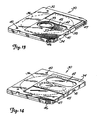
- Disk drive 10 is configured to use commercially available five and one-quarter inch optical disk cartridges 30 such as that illustrated in Figures 13 and 14.
- Cartridge 30 includes an enclosure 32, a sliding door 34, and a magneto-optic disk 36 positioned within the enclosure. The perimeter of disk 36 is illustrated in phantom in Figures 13 and 14.
- Disk 36 includes a pair of opposed recording surfaces 38 mounted about a hub 39. Data is stored in circular servo tracks 33 which are radially spaced about disk 36.
- the top and bottom of enclosure 32 have a pair of holes 40 which are engaged by locating pins 118 ( Figure 4) when cartridge 30 is positioned in drive 10.
- Both sides of enclosure 32 include recesses 46 which are engaged by latch clips ( Figure 15) to further secure cartridge 30 in drive 10.
- a pair of door sensor recesses 47 extend into opposite sides of the rear edge of enclosure 32.
- Door 34 includes a recess 41 which is engaged by a door opening mechanism ( Figures 2 and 3) to slide the door to its open position. Both sides of door 34 include an opening 42. When in its open position shown in Figure 13, openings 42 of door 34 will be positioned over openings 45 of a similar size and shape in both the bottom and top of enclosure 32, thereby exposing hub 39 and recording surfaces 38 of disk 36. When cartridge 30 is not in use, door 34 is biased by a spring (not shown) to a closed position shown in Figure 14. When in its closed position door 34 covers openings 45 and protectively encloses optical disk 36 within enclosure 32.
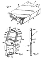
- a mechanical system of disk drive 10 is illustrated generally in Figures 2-4.
- the mechanical system includes cartridge retaining mechanism 48, cartridge door opening and sensor mechanism 49, baseplate assembly 50 and baseplate assembly drive mechanism 100.
- Baseplate assembly 50 includes rotary arm 70, optical assembly 71, tracking motor 72 and drive motor and spindle assembly 74, all of which are mounted to baseplate 76.
- cartridge 30 is securely latched in its inserted position by cartridge retaining mechanism 48.
- Cartridge door opening and sensor mechanism 49 opens cartridge door 34 as cartridge 30 is being inserted, and provides signals to the electrical system ( Figure 17) indicating whether or not the door has been properly opened. If cartridge door 34 is completely opened, drive mechanism 100 will raise baseplate assembly 50 from a lower or load/unload position to an upper or operative position.
- Drive motor and spindle assembly 74 engages and rotates disk 36 when baseplate assembly 50 is in its operative position.
- Tracking motor 72 drives and positions arm 70 about a tracking axis 25 with respect to servo tracks 33 on disk 36 as information is written, read and erased at bit positions by optical assembly 71.
- Cartridge retaining mechanism 48 and door opening and sensor mechanism 49 can be described with reference to Figures 2-4 and 15-16.
- Cartridge retaining mechanism 48 includes a pair of cartridge guides 51, one of which is secured to each side panel 16 and 18.
- Guides 51 include generally U-shaped cartridge edge receiving guide tracks 52 which extend rearwardly from the forward ends of side panels 15 and 15 for a distance equal to the length of cartridge 30. After it is inserted into drive 10 through door 26, the edges of cartridge 30 enter guide tracks 52.
- Guide tracks 52 guide cartridge 30 into drive 10 and support the cartridge in its inserted position.
- a latch cam recess 53, latch guide recesses 54 and latch clip recess 55 are all formed in the side wall of each guide 51, rearwardly of the associated guide track 52. Recesses 53, 54 and 55 all cooperate with a sliding latch member 56 which includes a hollow body 71, guide lugs 73, latch clip 57 and spring guide pin 58. As best shown in Figures I6A-16D, latch cam recess 52 includes four ramping track sections 59-62 which are separated by ledges and arranged in a cardioid pattern to form a closed one-way or unidirectional path having a cartridge release stop position 63 and a cartridge latch stop position 64.
- Each retainer clip recess 55 has an inner wall 65 and a sloping wall 79 which slopes out of recess 55 from the inner wall as it extends rearwardly along associated guide 51.
- Latch members 56 can be one-piece molded plastic members.
- Each latch clip 57 includes a living hinge section 66 which slopes toward the side of the latch 56 having guide lugs 73 as it extends from body 71.
- Each living hinge section 66 is terminated by an elongated tab 67.
- Latch members 56 are guided in reciprocal forward and rearward motion along guides 51 by guide lugs 73 which extend into latch guide recesses 54.
- a cam follower such as Z-shaped pin 68 is associated with each latch member 56 and has an end 75 which fits into hole 77 in the latch member and an end 69 which extends into and rides within tracks 59-62 of latch cam recess 53.
- Latch members 56 are biased toward the front of drive 10 by springs 81 which extend around guide pins 58.
- Latch members 56 function as push-type or touch-type latches.
- ends 69 of pins 68 will be in release stop positions 64 of cam recesses 53.
- Latch clips 57 will extend into latch clip recesses 55 when latch members 56 are in this position, with living hinge section 66 resting adjacent sloping side walls 79 and tabs 67 adjacent walls 65.
- Cartridge 30 is unlatched and ejected from disk drive 10 by a complementary push or touch motion.
- Pushing cartridge 30 into drive 10 causes ends 69 of pins 68 to travel along track sections 61 and into track sections 62 as shown in Figure 16C.
- springs 81 will force latch members 56 and cartridge 30 forward as pin ends 69 traverse track sections 62 and return to release stop positions 63 in track sections 61.
- Latch clips 57 will then retract into recesses 55, releasing cartridge 30.
- Release stop positions 64 are forwardly of latch stop positions 63 by a distance which causes the forward end of cartridge 30 to extend out of door 26. An operator can then grasp cartridge 30 and pull it out of drive 10.
- Door opening and sensor mechanism 49 includes a pair of sliding feeler assemblies 260, a pair of Hall-effect sensors 262 and left and right cartridge door opening links 264.
- Door opening links 264 are elongated members pivotally mounted by pins 266 to downwardly extending sections 268 of cartridge guides 11. Both links 264 includes a door engaging lug 265 at their free ends.
- Coil springs 270 ( Figure 4) bias links 264 to the extended positions shown in Figure 2.
- Right opening link 264 is positioned at a height equal to that of the top surface of cartridge 30 when the cartridge is loaded into the drive.
- Left opening link 264 extends parallel to the lower edge of cartridge 30, below right link 264.
- Feeler assemblies 260 are slidably mounted to latch members 56 and each includes a slide mount 270, forwardly extending feeler tab 272, permanent magnet 274 and spring 276.
- Slide mounts 270 engage grooves 278 in latch members 56, while springs 276 fit within cavities 280 in the latch members.
- Springs 276 bias feeler assemblies 260 to a forward position shown in Figure 2, with feeler tabs 272 extending beyond the forward edge of latch member bodies 71.
- Hall-effect sensors 262 are mounted to a support 282 and positioned at a location displaced from and not aligned with magnets 274 when feeler assemblies 260 and latch members 56 are in their forwardmost positions.
- Feeler tabs 272 are positioned adjacent door sensor recesses 47 of cartridge 30 when the cartridge is inserted into drive 30. If cartridge door 34 is fully opened when cartridge 30 is inserted into drive 10,one of door sensor recesses 47 will be covered by the door. Tab 272 of the feeler assembly 260 on the side of drive 10 adjacent door 34 will then be engaged by the door and forced rearwardly with respect to the associated latch member 56, moving the assemblies' magnet 274 under and adjacent to the associated Hall-effect sensor 262. The other feeler tab 272 will enter sensor recess 47 since it is not covered by door 34, preventing the slide mount 270 and associated magnet 274 from sliding rearwardly with respect to latch body 71.
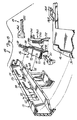
- Baseplate assembly 50 can be described generally with reference to Figure 4, which is a bottom view disk drive 10 with bottom panel 14 removed.
- Rotary arm 70, tracking motor 72 and drive motor and spindle assembly 74 are all mounted to baseplate 76.
- Baseplate 76 and all elements mounted thereto are pivotally suspended within disk drive 10 below guides 51 by flexure member 78.
- flexure member 78 is an elongated piece of tempered spring steel which extends along the back edge of baseplate 76, and is fastened to the top surface of the baseplate by screws 80.
- Opposite ends of flexure member 78 are fastened to brackets extending from side panels 16 and 18 by screws 82.
- Baseplate 76 is a generally planar member which includes a disk access aperture 86, a pair of structural apertures 88, and a drive motor and spindle assembly aperture 90 ( Figures 5 and 6). In one embodiment baseplate 76 is machined from aluminum.
- drive motor and spindle assembly 74 includes a mounting base 92 and a motor and spindle hub frame 94 which extends from the mounting base. Centering hub 95 is mounted to and extends from frame 94. Mounting base 92 is fastened to a lower surface of baseplate 76 by means of screws 96. Motor and spindle hub frame 94 extends through aperture 90 and beyond the upper surface of baseplate 76.
- a preferred embodiment of drive motor and spindle assembly 74 is described in copending application Serial No. 246,502, filed September 19, 1988 and assigned to the same assignee as the present invention. Other drive motor and spindle assemblies can also be used.
- Baseplate assembly 50 is driven between its cartridge load/unload position and its operative position by drive mechanism 100.
- Drive mechanism 100 includes motor 102 and worm gear 104 which are mounted to front panel 20 by bracket 106.
- Motor 102 rotates worm gear 104 about a generally horizontal axis.
- a threaded shaft 108 and coaxially mounted gear 110 are rotatably mounted in a vertical orientation adjacent worm gear 104 by means of bracket 112.
- Shaft 108 extends through threaded nut 114 which is attached to the lower side of baseplate 76 by screws 116.
- Motor 102 is controlled by the electrical subsystem of disk drive 10.
- Cartridge 30 is loaded into and unloaded from disk drive 10 when baseplate assembly 50 is pivoted downward to its cartridge load/unload position shown in Figure 5.
- Centering hub 95 of motor and spindle hub frame 74 is located below cartridge 30 when the cartridge is in its load/unload position.
- motor 102 is actuated and causes threaded shaft 108 to rotate in a first direction forcing nut 114 and baseplate assembly 50 into its operative position shown in Figure 6.
- Locating pins 118 which extend upwardly from the forward corners of baseplate 76 are then positioned in holes 40 of cartridge 30 to ensure proper alignment between baseplate assembly 50 and the cartridge.
- Centering hub 95 will also extend through opening 45 of cartridge 30 and engage hub 39 of optical disk 36.
- tracking motor 72 can be actuated to drive arm 70 about tracking axis 25 to position optical assembly 71 adjacent desired servo tracks 33 on disk 36. Digital information can then be written, read and erased at bit positions on servo tracks 33. If it is desired to remove cartridge 30 from drive 10 after these operations are completed, motor 102 is again actuated. When shaft 108 is rotated in a second direction baseplate assembly 50 is lowered to its cartridge load/unload position and disengaged from cartridge 30. Cartridge 30 can then be removed from drive 10 in the manner previously described.
- Rotary arm 70 and tracking motor 72 can be described with reference to Figures 7 and 8.
- arm 70 includes an elongated and generally planar base 124 surrounded by a wall 126 which extends in a perpendicular direction from both sides of the base.
- a cylindrical pivot housing 128 is formed in wall 126 at one end of arm 70, while a generally cylindrical focus and bias field switching assembly housing 130 is formed in the wall at the opposite end of the arm. Housing 130 extends beyond the upper edge of wall 126 in the embodiment shown.
- the distance between the center of housing 128 and the center of housing 130 is fifty-nine and one-quarter millimeters about a longitudinal axis parallel to the portion of wall 126 opposite base 124 from the wall portion intersecting the two housings, and nine and four-tenths millimeters about a transverse axis perpendicular to the longitudinal axis.
- Arm 70 is fabricated from magnesium in one embodiment. The described design of arm 70 is lightweight with low inertia, yet rigid to resist bending forces.
- Rotary arm 70 is pivotally mounted to baseplate 76 by pivot assembly 132.
- pivot assembly 132 includes upper ball bearing assembly 133, lower ball bearing assembly 134, flanged sleeve 135 and bolt 136.
- Bearing assemblies 133 and 134 each have an inner race IR and outer race OR.
- Outer races OR of bearing assemblies 133 and 134 are separated by spacer 137 and bonded to the interior surface of pivot housing 128.
- Inner races IR of bearing assemblies 133 and 134 are preloaded (i.e. forced toward one another) and bonded to an exterior surface of sleeve 135.
- Arm 70 is secured to baseplate 76 by bolt 136.
- flanged end 138 of sleeve 135 is positioned between baseplate 76 and arm 70, and ensures that the baseplate and arm are parallel to one another. Preloading inner races IR of bearing assemblies 133 and 134 effectively increases the virtual stiffness of the bearings and contributes to the overall performance of drive 10.
- the distance between the center of pivot assembly 132 and the axis of rotation of drive motor and spindle assembly 74 is fifty millimeters along an axis parallel to the forward edge of the baseplate, and sixteen millimeters along an axis parallel to the side edge of the baseplate.
- optical and opto-electronic elements of disk drive 10 are mounted to rotary arm 70. These elements include laser diode 142, collimator lens 144, beam shaping prism 146, turn-around prism 148, focus and bias field switching assembly 150, sensor lens 152, polarizing beam splitter 154, and optical detectors 156 and 158.
- Laser diode 142 is mounted within an extended portion of wall 126 and produces a laser beam 160 which is illustrated by broken lines in Figure 71
- Laser beam 160 is collimated by lens 144 before it is impinged upon beam shaping prism 146.
- Prism 146 changes the aspect ratio of collimated beam 160 from approximately three-to-one to one-to-one.
- Laser beam 160 then passes through a leaky coating (not visible) between prisms 146 and 148 before it is directed to focus and bias field switching assembly 150 from prism 148.
- the leaky coating allows seventy percent transmission of p-polarization components of laser beam 160 and zero percent transmission of s-polarization components. This ratio is a compromise for write and read requirements.
- the leaky coating also introduces little or no phase shift between the p- and s-polarization components of beam 160.
- incident portions of laser beam 160 are directed to focus and bias field switching assembly 150 through an aperture 194 ( Figure 9) in housing 130.
- focus and bias field switching assembly 150 reflects incident laser beam 160 toward and focuses the beam onto optical disk 36.
- the polarization angle of incident beam 160 is then modulated by the magnetic orientation of bit positions on optical disk 36 in accordance with known magneto-optic principles, and the beam reflected back to turn-around prism 148 through focusing and bias field switching assembly 150.
- the modulated and reflected portions of laser beam 160 are directed to polarizing beam splitter 154 through sensor lens 152 by turn-around prism 148.
- Sensor lens 152 shapes the reflected beam for proper focus control.
- Beam splitter 154 splits the modulated and reflected portions of beam 16 into its s- and p- polarization components, and impinges each of these components upon one of detectors 156 and 158.
- At least one of detectors 156 and 158 is capable of producing signals representative of focus and tracking errors of objective lens 170 ( Figure 9) with respect to servo tracks 3 and disk 36.
- Focus and tracking error signals generated as a function of the detector signals are used by focus and tracking servo systems, respectively, of the electrical subsystem to properly focus beam 160 onto disk 36 and to track desired servo tracks 33.
- An information signal representative of the digital state of data read from optical disk 36 is derived differentially from the signals produced by detectors 156 and 158.
- detectors 156 and 158 are central bar detectors of the type shown in copending application Serial Number 265,219 filed October 31, 1988 and assigned to the same assignee as the present invention.
- Focus and bias field switching assembly 150 is shown in greater detail in Figures 9 and 10.
- Assembly 150 includes a focusing assembly !64 and a bias field assembly 162.
- Focusing assembly 164 includes a generally planar metallic pole piece 166, objective lens support 168, objective lens 170, and prism 172.
- Pole piece 166 is a circular member bonded by epoxy to a first or lower edge of housing 130.
- Pole piece 166 has a circular central aperture 174 and a pair of elongated apertures 176 positioned on opposite sides of the circular aperture.
- a pair of permanent magnets 178 are bonded to opposite sides of each elongated aperture 176, and are radially spaced from 1ne another with respect to central aperture 174.
- Lens support 168 is preferably a one-piece plastic member which includes a lower mounting section 180, middle prism cage section 182, and upper lens mount section 184. Sections 180, 182 and 184 are vertically spaced about the path of laser beam 160 between prism 172 and optical disk 36 (i.e., perpendicular to the disk and parallel to the optical axis of lens 170).
- One side of prism cage section 182 has a beam opening 186 which extends into prism cavity 188.
- An elongated opening 190 extends through lens support 168 between lens mount section 184 and prism cavity 188, forming a path for beam 160.
- Objective lens 170 is mounted within lens mount section 184 of lens support 168 using epoxy or other means.
- Prism 172 is positioned within cavity 188 and is fixedly mounted to housing 130 by means of a support such as 192 ( Figure 9).
- Beam opening 186 which extends into prism cage section 182 of lens support 168 is aligned with an opening 194 which extends through housing 130.
- Incident portions of laser beam 160 are directed to focus and bias field switching assembly 150 through openings 194 and 186 before being reflected by prism 172, directed through objective lens 170, and impinged upon bit positions of optical disk 36.
- Modulated portions of laser beam 160 which are reflected from the optical disk traverse an identical path before they are directed back through turn-around prism 148 to detectors 156 and 158.
- a pair of leaf springs 196 movably and resiliently suspend lens support 168 within housing 130.
- Each spring 196 has a circular outer rim 198, a circular inner rim 200, and a leaf member 202 extending between the inner and outer rims.
- Outer rim 200 of the lower spring 196 is bonded to a lower edge of pole piece 166, while its inner rim 200 is secured to mounting section 180 of lens support 168 by fastening plug 204.
- Upper spring 196 has its outer rim 198 bonded to an upper edge of housing 130 and its inner rim 200 secured to lens mount section 184 of lens support 168.
- a pair of wire coils 206 are secured to opposite sides of lens support 182. As shown in Figures 9 and 10, coils 206 extend into elongated apertures 176 between magnets 178. Magnetic fields generated by coils 206 in response to focus drive signals produced by the electrical system interact with the magnetic fields produced by magnets 178. Lens support 168 and objective lens 170 are thereby driven against the bias force of springs 200 and positioned along focus axis 23 to focus laser beam 160 onto disk 36.
- Bias field assembly 162 includes an annular permanent magnet 210 and an actuator mechanism 212 for driving the magnet between write and erase positions with respect to optical disk 36.
- Actuator mechanism 212 lu includes a ring-shaped plastic coil form and magnet housing 214 which is mounted to an upper edge of housing 130 by means of mounting ring 216. Coils 218 and 220 are wound about recesses in the exterior surface of housing 214.
- Actuator mechanism 212 also includes magnet sliding guide 222 which has a ring-shaped magnet receiving face 224 and a plurality of legs 226 which extend downward into housing 130 from magnet housing 214.
- ring magnet 210 and face 224 of guide 222 are concentrically positioned around lens mount section 184 of lens support 168.
- Magnet 210 and guide 222 are movable within magnet housing 214 between a write position illustrated in solid lines in Figures 9 and 10, and an erase position illustrated in broken lines in Figure 9.
- magnet 210 When in its write position, magnet 210 will be positioned at a distance from optical disk 36 which causes a magnetic B field having a value less than or equal to the required write threshold to be impinged upon the bit positions onto which laser beam 160 is focused.
- magnet 210 When moved to its erase position, magnet 210 will be at a 1, distance from disk 36 which causes a magnetic B field having a value greater than or equal to the erase threshold to be impinged upon the bit positions. With magnet 210 in its erase position, data can be erased from the bit positions.
- the polarity of the magnetic B field which is applied to optical disk 36 when magnet 20 is in its write position is opposite the polarity of the field impinged upon the disk when the magnet is in its erase position.
- Guide 222 prevents magnet 210 from becoming cocked or wedged within magnet housing 214 while it is being driven between its write and erase positions. As shown in Figure 9, portions of legs 226 ride along an interior surface of housing 130 while guide 222 and magnet 210 are moved together. Magnet housing 214 also includes several grooves 228 on its interior surface. Guide lugs 230 which extend radially outward from the edges of guide face 224 ride within grooves 228. Lugs 230 engage mounting ring 216 when magnet 210 is in its write position, and prevent further movement of the magnet and guide 222 away from optical disk 36. The movement of magnet 210 toward optical disk 36 is limited to the erase position when lugs 230 engage the upper ends of grooves 228.
- Magnet 210 is held in both the write and erase positions by its magnetic attraction to ferro-magnetic members 232.
- Members 232 are mounted within recesses in the interior surface of magnet housing 214 adjacent magnet 210 in both its write and erase positions. The size of members 232 and the distance between them and edges of magnet 210 can be adjusted to control the retaining force needed to hold magnet 210 in its write or erase positions.
- coils 218 and 220 are located in planes parallel to the pole surfaces of magnet 210.
- Coils 218 are positioned on magnet housing 214 in such a manner that the center 234 of the plane in which they are located is positioned closer to the top edge of the magnet housing than the center 236 of the edge of magnet 210 when the magnet is in its erase position.
- Coils 220 are positioned on magnet housing 214 at such a location that the center 238 of the plane in which they are located is closer to the lower edge of the magnet housing than center 240 of the edge of magnet 210 when the magnet is in its write position.
- Coils 218 and 220 are connected in series with one another and function in a solenoid-like manner. As indicated by the dot and arrow current flow convention used in Figure 10, coils 218 are wound in a direction opposite that of coils 220. In response to a bias field select pulse of a first or positive polarity applied to coils 218 and 220, the magnetic fields generated by the coils will interact with the magnetic fields of magnet 210 and force the magnet to its write position. Magnet 210 will be held in the write position by its attractive force with ferro-magnetic members 232 adjacent coils 220.
- bias field select pulse of a second or negative polarity When a bias field select pulse of a second or negative polarity is applied to coils 218 and 220, the magnetic fields generated by these coils will interact with the field of magnet 210 and force the magnet to its erase position. Magnet 210 will be held in its erase position by its attractive force with ferro-magnetic members 232 adjacent coils 218. The polarity of the bias field select pulse applied to coils 218 and 220 therefore determines whether magnet 210 is located in its write or erase positions.
- Tracking motor 72 can be described with reference to Figures 4, 7, 11 and 12.
- Tracking motor 72 is a moving coil linear motor and includes coil assembly 122 and magnet assembly 252.
- Coil assembly 122 can be formed in a mold (not shown) by winding a first wire coil 244 around coil forming pins 242A-242D and a second coil 246 around pins 242E-242H.
- a rigid polymer base 240 is then molded around coils 244 and 246.
- Active portions 244A and 244B of coil 244 and active portions 246A and 246B of coil 246 are all coplanar and overlap in an arcuate central track 243 of base 240.
- Tracking coil assembly 122 is rigidly fastened to arm 70 by fitting base 240 between a pair of generally parallel shelves 248 which extend from the arm opposite focus and bias field switching assembly 150 from pivot assembly 132. Screw 250 and adhesive are used to bolt tracking motor coil assembly 122 to arm 70.
- Magnet assembly 252 is rigidly mounted to baseplate 76 adjacent tracking coil assembly 122.
- Magnet assembly 252 includes a magnet mount 254 having a generally U-shaped cross section and a pair of planar faces which extend over the opposite sides of coil assembly 122.
- Two pair of permanent magnets 256 and 258 are mounted on the interior surface of each face of magnet mount 254, and are positioned between ridges 245 in track 243 of base 240.
- Magnets 256 and 258 are parallel to coils 244 and 246.
- magnetic fields produced by the coils will interact with the magnetic fields of magnets 256 and 258, and drive arm 70 in a plane parallel to disk 36.
- Objective lens 170 and laser beam 160 can thereby track or be centered over desired servo tracks 33 on disk 36.
- control and signal processing circuitry 292 is interfaced to a host computer over bus 294.
- control and signal processing circuitry 292 includes a programmable digital signal processor and associated memory which are mounted to the inside surface of top panel 12.
- control and signal processing circuitry 292 will monitor Hall-effect sensors 262 to determine whether or not cartridge door 34 has been properly opened to allow access to disk 36. If sensors 262 indicate that door 34 has been opened, motor 102 will be actuated to raise baseplate assembly 50 from its load/unload position to its operative position. Centering hub 95 of drive motor and spindle assembly 74 will then engage hub 39 of disk 36. Drive motor and spindle assembly 74 are subsequently actuated to rotate optical disk 36.
- laser 142 will generate and impinge laser beam 160 upon the disk.
- Tracking and focus servo systems which include control and signal processing circuitry 292, will generate tracking and focus drive signals in response to signals provided by detectors 156 and/or 158.
- the focus and tracking drive signals are applied to focus and tracking motor coils 206 and 244, 246, respectively, to keep laser beam 160 in focus and tracking servo tracks 33 on disk 36.
- the intensity of laser beam 160 is modulated and switched between intensity levels in phase with bias field switching signals applied to bias field switching assembly coils 218, 220 to read, write and erase data at individual bit positions on disk 36.
- the information written to and read from disk 36 is transmitted between circuitry 292 and the host computer over bus 294.
- Switch 15 is actuated when the operated wants to remove cartridge 30 from disk drive 10.
- control and signal processing circuitry 292 provides a stop request to the host computer.
- drive motor and spindle assembly 74 is stopped to allow the optical disk to spin down.
- baseplate assembly drive motor 102 will be actuated and drive baseplate assembly 50 to its load/unload position. The operator can then remove cartridge 30 from disk drive 10 in the manner previously described.
- the operating status of disk drive 10 is indicated to the operator by LED display 17.
- Disk drive 10 has considerable advantages over those of the prior art.
- the low profile and compact nature of all of its components, including baseplate assembly 50, rotary arm 70, tracking motor 72, and focus and bias field switching assembly 150 facilitate assembly into a half-height enclosure.
- tracking motor 72 directly adjacent to focus and bias field switching assembly 150 (i.e. by direct coupling these two assemblies), and opposite the assembly from pivot mechanism 130, the effects of arm and bearing dynamics upon tracking servo system response are reduced.
- the phase and magnitude of movement of objective lens 170 are caused by the forces generated by tracking motor 72, and are primarily determined by the stiffness of coupling between coils 244, 246 and the objective lens. This stiffness is not controlled by the structure of arm 70 between objective lens 170 and pivot assembly 132, or by bearing 134.
Landscapes
- Physics & Mathematics (AREA)
- Optics & Photonics (AREA)
Applications Claiming Priority (2)
| Application Number | Priority Date | Filing Date | Title |
|---|---|---|---|
| US07/401,620 US5132944A (en) | 1988-09-20 | 1989-08-31 | Half-height magneto-optic disk drive |
| US401620 | 2003-03-27 |
Publications (3)
| Publication Number | Publication Date |
|---|---|
| EP0415543A2 true EP0415543A2 (de) | 1991-03-06 |
| EP0415543A3 EP0415543A3 (en) | 1992-11-25 |
| EP0415543B1 EP0415543B1 (de) | 1998-09-02 |
Family
ID=23588496
Family Applications (1)
| Application Number | Title | Priority Date | Filing Date |
|---|---|---|---|
| EP90307980A Expired - Lifetime EP0415543B1 (de) | 1989-08-31 | 1990-07-20 | Magneto-optische Platteneinheit mit halber Dicke |
Country Status (3)
| Country | Link |
|---|---|
| US (1) | US5132944A (de) |
| EP (1) | EP0415543B1 (de) |
| DE (1) | DE69032612T2 (de) |
Cited By (5)
| Publication number | Priority date | Publication date | Assignee | Title |
|---|---|---|---|---|
| EP0426763A4 (en) * | 1988-09-20 | 1992-09-16 | Hewlett-Packard Company | Bias field switching system for magneto-optic disk drive |
| EP0553551A3 (en) * | 1992-01-21 | 1994-10-19 | Fujitsu Ltd | Optical disk apparatus having a reduced size |
| EP0579172A3 (en) * | 1992-07-13 | 1996-05-22 | Sony Corp | Disc cartridge loading device |
| US5623457A (en) * | 1993-04-12 | 1997-04-22 | Sony Corporation | Photomagnetic disc drive system having a locking mechanism |
| US5815470A (en) * | 1994-08-11 | 1998-09-29 | Sony Corporation | Disc drive unit |
Families Citing this family (14)
| Publication number | Priority date | Publication date | Assignee | Title |
|---|---|---|---|---|
| JP3428030B2 (ja) * | 1991-05-28 | 2003-07-22 | ソニー株式会社 | ディスク記録及び/又は再生装置 |
| JPH04351784A (ja) * | 1991-05-28 | 1992-12-07 | Sony Corp | ディスク記録及び/又は再生装置 |
| JPH05174390A (ja) * | 1991-06-21 | 1993-07-13 | Sony Corp | 光学ブロックの支持機構 |
| US5428583A (en) * | 1991-10-31 | 1995-06-27 | Sony Corporation | Magneto-optical disc recording/reproducing apparatus |
| US5329503A (en) * | 1991-10-31 | 1994-07-12 | Sony Corporation | Magneto-optical disc recording/reproducing apparatus |
| JP3018686B2 (ja) * | 1991-11-15 | 2000-03-13 | ソニー株式会社 | 光学ピックアップ装置の支持機構 |
| US5524343A (en) * | 1994-03-18 | 1996-06-11 | Seagate Technology, Inc. | Press-fit glueless bearing pivot assembly |
| US5742441A (en) * | 1995-04-07 | 1998-04-21 | Discovision Associates | Method and apparatus for aligning an objective lens |
| US5708633A (en) * | 1995-06-07 | 1998-01-13 | Discovision Associates | Method and apparatus for manufacturing information storage devices |
| JP2000003522A (ja) | 1998-06-15 | 2000-01-07 | Fujitsu Ltd | 光ディスク装置 |
| US20020101816A1 (en) * | 1999-05-20 | 2002-08-01 | Michael F. Braitberg | Removable optical storage device and system |
| JP2007257725A (ja) * | 2006-03-23 | 2007-10-04 | Hitachi Ltd | 光ディスク装置 |
| US10861493B1 (en) * | 2014-07-29 | 2020-12-08 | Kla Corporation | Magneto-optic systems with multi-ID disk positioning |
| DE102016218391A1 (de) * | 2016-09-23 | 2018-03-29 | Röchling Automotive SE & Co. KG | Magnetfeld-basierte Betriebszustandserfassung von Luftklappen |
Family Cites Families (29)
| Publication number | Priority date | Publication date | Assignee | Title |
|---|---|---|---|---|
| GB1525696A (en) * | 1974-11-18 | 1978-09-20 | Rca Corp | Lid interlock system |
| US3983317A (en) * | 1974-12-09 | 1976-09-28 | Teletype Corporation | Astigmatizer for laser recording and reproducing system |
| US4013033A (en) * | 1976-01-28 | 1977-03-22 | Porter Stephen G | Weed guard for trolling motors |
| NL182609C (nl) * | 1977-02-10 | 1988-04-05 | Philips Nv | Videoplatenspeler. |
| NL7703232A (nl) * | 1977-03-25 | 1978-09-27 | Philips Nv | Optische aftastinrichting. |
| US4340955A (en) * | 1978-03-27 | 1982-07-20 | Discovision Associates | Video disc player |
| US4326284A (en) * | 1980-05-09 | 1982-04-20 | Rca Corporation | Video disc player having turntable assist apparatus |
| JPS6138145Y2 (de) * | 1980-08-14 | 1986-11-04 | ||
| NL8300133A (nl) * | 1983-01-14 | 1984-08-01 | Philips Nv | Inrichting voor het met behulp van een stralingsbundel inschrijven en/of uitlezen van informatie. |
| KR870001132B1 (ko) * | 1983-04-14 | 1987-06-09 | 도오요오 보오세끼 가부시끼가이샤 | 제전성섬유 및 그 제조방법 |
| US4519055A (en) * | 1983-04-19 | 1985-05-21 | The United States Of America As Represented By The Secretary Of The Air Force | Optical disc transport system |
| US4545045A (en) * | 1983-05-31 | 1985-10-01 | Storage Technology Partners Ii | Recording disk load and unload apparatus |
| NL8303700A (nl) * | 1983-10-27 | 1985-05-17 | Philips Nv | Electro-optische inrichting. |
| DE3469236D1 (en) * | 1983-11-08 | 1988-03-10 | Philips Nv | A disc-record player with a loading device for loading a disc into the record player |
| US4818066A (en) * | 1984-01-30 | 1989-04-04 | Canon Kabushiki Kaisha | Objective lens driving device |
| DE3573853D1 (en) * | 1984-01-31 | 1989-11-23 | Matsushita Electric Industrial Co Ltd | Pick-up arm for an optical disk player |
| JPS60231964A (ja) * | 1984-04-28 | 1985-11-18 | Canon Inc | 記録又は再生装置 |
| DE3424456A1 (de) * | 1984-07-03 | 1986-01-09 | Nixdorf Computer Ag, 4790 Paderborn | Elektrodynamischer antrieb zur schwenkbewegung eines oder mehrerer traegerarme fuer wandlerkoepfe von plattenspeichern |
| US4752922A (en) * | 1984-07-06 | 1988-06-21 | Storage Technology Partners 11 | Optical disk recording and readout system having read, write and coarse light beams |
| JPH0325319Y2 (de) * | 1985-07-13 | 1991-05-31 | ||
| JPH0668843B2 (ja) * | 1985-08-16 | 1994-08-31 | ソニー株式会社 | 光学ピツクアツプ装置 |
| US4823214A (en) * | 1985-09-19 | 1989-04-18 | Laser Magnetic Storage International Company | Disk drive for cartridge disks |
| JPS62273652A (ja) * | 1986-05-21 | 1987-11-27 | Copal Co Ltd | デイスクカ−トリツジのシヤツタ開閉機構 |
| JPS6320732A (ja) * | 1986-07-11 | 1988-01-28 | Olympus Optical Co Ltd | デイスク用光ピツクアツプ |
| US4736356A (en) * | 1986-07-14 | 1988-04-05 | Optotech, Inc. | Optical disk drive |
| JPH0348765Y2 (de) * | 1986-10-13 | 1991-10-17 | ||
| EP0273071B1 (de) * | 1986-12-30 | 1991-08-28 | Ibm Deutschland Gmbh | Schwenkbarer Zugriffsarm für optische Platten |
| NL8701526A (nl) * | 1987-06-30 | 1989-01-16 | Philips Nv | Inrichting voor het optisch aftasten van een roterende plaat. |
| JPH01184653A (ja) * | 1988-01-11 | 1989-07-24 | Fuji Photo Film Co Ltd | テープレコーダ |
-
1989
- 1989-08-31 US US07/401,620 patent/US5132944A/en not_active Expired - Lifetime
-
1990
- 1990-07-20 DE DE69032612T patent/DE69032612T2/de not_active Expired - Fee Related
- 1990-07-20 EP EP90307980A patent/EP0415543B1/de not_active Expired - Lifetime
Cited By (8)
| Publication number | Priority date | Publication date | Assignee | Title |
|---|---|---|---|---|
| EP0426763A4 (en) * | 1988-09-20 | 1992-09-16 | Hewlett-Packard Company | Bias field switching system for magneto-optic disk drive |
| EP0553551A3 (en) * | 1992-01-21 | 1994-10-19 | Fujitsu Ltd | Optical disk apparatus having a reduced size |
| US6052357A (en) * | 1992-01-21 | 2000-04-18 | Fujitsu Limited | Compact optical disk apparatus having a swing-motion optical head |
| EP0862168A3 (de) * | 1992-01-21 | 2001-05-16 | Fujitsu Limited | Optisches Plattengerät mit reduzierten Abmessungen |
| EP0579172A3 (en) * | 1992-07-13 | 1996-05-22 | Sony Corp | Disc cartridge loading device |
| US5623457A (en) * | 1993-04-12 | 1997-04-22 | Sony Corporation | Photomagnetic disc drive system having a locking mechanism |
| US5815470A (en) * | 1994-08-11 | 1998-09-29 | Sony Corporation | Disc drive unit |
| US5841752A (en) * | 1994-08-11 | 1998-11-24 | Sony Corporation | Disc drive unit |
Also Published As
| Publication number | Publication date |
|---|---|
| DE69032612D1 (de) | 1998-10-08 |
| EP0415543A3 (en) | 1992-11-25 |
| EP0415543B1 (de) | 1998-09-02 |
| DE69032612T2 (de) | 1999-01-28 |
| US5132944A (en) | 1992-07-21 |
Similar Documents
| Publication | Publication Date | Title |
|---|---|---|
| US5132944A (en) | Half-height magneto-optic disk drive | |
| RU2056647C1 (ru) | Устройство для записи и/или воспроизведения с оптического диска | |
| EP0652558A2 (de) | Plattenkassette-Falscheinlege-Verhinderungsmechanismus | |
| US4442516A (en) | Drive mechanism for disc player with bearing supported slider | |
| US4764831A (en) | Apparatus and method for retaining a head arm of a disk drive assembly | |
| US4932019A (en) | Disk player having a vibration dissipating device | |
| JP3191816B2 (ja) | バイアス磁界発生方法、データ書き込み消去装置、及び光磁気ディスク・ドライブ装置 | |
| US7103895B2 (en) | Optical pickup device, and recorder and/or player | |
| US5216643A (en) | Rotary arm and optical head for a magneto-optic disk drive | |
| KR100275710B1 (ko) | 대물렌즈 구동 장치 | |
| US5218488A (en) | Method and apparatus for producing write and erase magnetic field for disk drive | |
| US5029157A (en) | Disk player having a pickup securing device | |
| JP2944379B2 (ja) | 光ディスクプレーヤ | |
| JP3076670B2 (ja) | 光磁気ディスク装置 | |
| JP3271217B2 (ja) | ディスクドライブ装置 | |
| JPH04141830A (ja) | 光学ヘッド及びディスク駆動装置 | |
| KR100245964B1 (ko) | 기록 및 재생장치 | |
| JP2915207B2 (ja) | 光記録再生装置 | |
| KR0170307B1 (ko) | 광디스크 기록/재생 장치 | |
| US20040244020A1 (en) | Disk recording and reproducing device | |
| JPH0714180A (ja) | 光学ピックアップ装置のキャリッジ駆動装置 | |
| JPH04232622A (ja) | 分離型光学ヘッド | |
| JPH05101554A (ja) | 光磁気デイスクライブラリ装置 | |
| JPS61261886A (ja) | 画像情報処理装置 | |
| JPH05182236A (ja) | 光ディスクドライブ装置 |
Legal Events
| Date | Code | Title | Description |
|---|---|---|---|
| PUAI | Public reference made under article 153(3) epc to a published international application that has entered the european phase |
Free format text: ORIGINAL CODE: 0009012 |
|
| AK | Designated contracting states |
Kind code of ref document: A2 Designated state(s): DE FR GB |
|
| PUAL | Search report despatched |
Free format text: ORIGINAL CODE: 0009013 |
|
| AK | Designated contracting states |
Kind code of ref document: A3 Designated state(s): DE FR GB |
|
| 17P | Request for examination filed |
Effective date: 19930430 |
|
| 17Q | First examination report despatched |
Effective date: 19940516 |
|
| GRAG | Despatch of communication of intention to grant |
Free format text: ORIGINAL CODE: EPIDOS AGRA |
|
| GRAG | Despatch of communication of intention to grant |
Free format text: ORIGINAL CODE: EPIDOS AGRA |
|
| GRAH | Despatch of communication of intention to grant a patent |
Free format text: ORIGINAL CODE: EPIDOS IGRA |
|
| GRAH | Despatch of communication of intention to grant a patent |
Free format text: ORIGINAL CODE: EPIDOS IGRA |
|
| GRAA | (expected) grant |
Free format text: ORIGINAL CODE: 0009210 |
|
| AK | Designated contracting states |
Kind code of ref document: B1 Designated state(s): DE FR GB |
|
| REF | Corresponds to: |
Ref document number: 69032612 Country of ref document: DE Date of ref document: 19981008 |
|
| ET | Fr: translation filed | ||
| PLBE | No opposition filed within time limit |
Free format text: ORIGINAL CODE: 0009261 |
|
| STAA | Information on the status of an ep patent application or granted ep patent |
Free format text: STATUS: NO OPPOSITION FILED WITHIN TIME LIMIT |
|
| 26N | No opposition filed | ||
| REG | Reference to a national code |
Ref country code: GB Ref legal event code: 732E |
|
| REG | Reference to a national code |
Ref country code: FR Ref legal event code: TP |
|
| REG | Reference to a national code |
Ref country code: GB Ref legal event code: IF02 |
|
| PGFP | Annual fee paid to national office [announced via postgrant information from national office to epo] |
Ref country code: GB Payment date: 20050713 Year of fee payment: 16 |
|
| PGFP | Annual fee paid to national office [announced via postgrant information from national office to epo] |
Ref country code: FR Payment date: 20050718 Year of fee payment: 16 |
|
| PGFP | Annual fee paid to national office [announced via postgrant information from national office to epo] |
Ref country code: DE Payment date: 20050831 Year of fee payment: 16 |
|
| PG25 | Lapsed in a contracting state [announced via postgrant information from national office to epo] |
Ref country code: GB Free format text: LAPSE BECAUSE OF NON-PAYMENT OF DUE FEES Effective date: 20060720 |
|
| PG25 | Lapsed in a contracting state [announced via postgrant information from national office to epo] |
Ref country code: DE Free format text: LAPSE BECAUSE OF NON-PAYMENT OF DUE FEES Effective date: 20070201 |
|
| GBPC | Gb: european patent ceased through non-payment of renewal fee |
Effective date: 20060720 |
|
| REG | Reference to a national code |
Ref country code: FR Ref legal event code: ST Effective date: 20070330 |
|
| PG25 | Lapsed in a contracting state [announced via postgrant information from national office to epo] |
Ref country code: FR Free format text: LAPSE BECAUSE OF NON-PAYMENT OF DUE FEES Effective date: 20060731 |