EP0415699B1 - Dispositif d'enregistrement et de reproduction d'un signal vidéo numérique - Google Patents
Dispositif d'enregistrement et de reproduction d'un signal vidéo numérique Download PDFInfo
- Publication number
- EP0415699B1 EP0415699B1 EP90309378A EP90309378A EP0415699B1 EP 0415699 B1 EP0415699 B1 EP 0415699B1 EP 90309378 A EP90309378 A EP 90309378A EP 90309378 A EP90309378 A EP 90309378A EP 0415699 B1 EP0415699 B1 EP 0415699B1
- Authority
- EP
- European Patent Office
- Prior art keywords
- block
- error
- video signal
- signal
- blocks
- Prior art date
- Legal status (The legal status is an assumption and is not a legal conclusion. Google has not performed a legal analysis and makes no representation as to the accuracy of the status listed.)
- Expired - Lifetime
Links
Images




Classifications
-
- G—PHYSICS
- G11—INFORMATION STORAGE
- G11B—INFORMATION STORAGE BASED ON RELATIVE MOVEMENT BETWEEN RECORD CARRIER AND TRANSDUCER
- G11B27/00—Editing; Indexing; Addressing; Timing or synchronising; Monitoring; Measuring tape travel
- G11B27/02—Editing, e.g. varying the order of information signals recorded on, or reproduced from, record carriers
- G11B27/031—Electronic editing of digitised analogue information signals, e.g. audio or video signals
- G11B27/032—Electronic editing of digitised analogue information signals, e.g. audio or video signals on tapes
-
- G—PHYSICS
- G11—INFORMATION STORAGE
- G11B—INFORMATION STORAGE BASED ON RELATIVE MOVEMENT BETWEEN RECORD CARRIER AND TRANSDUCER
- G11B20/00—Signal processing not specific to the method of recording or reproducing; Circuits therefor
- G11B20/00086—Circuits for prevention of unauthorised reproduction or copying, e.g. piracy
-
- G—PHYSICS
- G11—INFORMATION STORAGE
- G11B—INFORMATION STORAGE BASED ON RELATIVE MOVEMENT BETWEEN RECORD CARRIER AND TRANSDUCER
- G11B20/00—Signal processing not specific to the method of recording or reproducing; Circuits therefor
- G11B20/10—Digital recording or reproducing
- G11B20/18—Error detection or correction; Testing, e.g. of drop-outs
- G11B20/1806—Pulse code modulation systems for audio signals
- G11B20/1809—Pulse code modulation systems for audio signals by interleaving
-
- H—ELECTRICITY
- H04—ELECTRIC COMMUNICATION TECHNIQUE
- H04N—PICTORIAL COMMUNICATION, e.g. TELEVISION
- H04N19/00—Methods or arrangements for coding, decoding, compressing or decompressing digital video signals
- H04N19/10—Methods or arrangements for coding, decoding, compressing or decompressing digital video signals using adaptive coding
- H04N19/134—Methods or arrangements for coding, decoding, compressing or decompressing digital video signals using adaptive coding characterised by the element, parameter or criterion affecting or controlling the adaptive coding
- H04N19/142—Detection of scene cut or scene change
-
- H—ELECTRICITY
- H04—ELECTRIC COMMUNICATION TECHNIQUE
- H04N—PICTORIAL COMMUNICATION, e.g. TELEVISION
- H04N19/00—Methods or arrangements for coding, decoding, compressing or decompressing digital video signals
- H04N19/10—Methods or arrangements for coding, decoding, compressing or decompressing digital video signals using adaptive coding
- H04N19/169—Methods or arrangements for coding, decoding, compressing or decompressing digital video signals using adaptive coding characterised by the coding unit, i.e. the structural portion or semantic portion of the video signal being the object or the subject of the adaptive coding
- H04N19/179—Methods or arrangements for coding, decoding, compressing or decompressing digital video signals using adaptive coding characterised by the coding unit, i.e. the structural portion or semantic portion of the video signal being the object or the subject of the adaptive coding the unit being a scene or a shot
-
- H—ELECTRICITY
- H04—ELECTRIC COMMUNICATION TECHNIQUE
- H04N—PICTORIAL COMMUNICATION, e.g. TELEVISION
- H04N19/00—Methods or arrangements for coding, decoding, compressing or decompressing digital video signals
- H04N19/85—Methods or arrangements for coding, decoding, compressing or decompressing digital video signals using pre-processing or post-processing specially adapted for video compression
- H04N19/87—Methods or arrangements for coding, decoding, compressing or decompressing digital video signals using pre-processing or post-processing specially adapted for video compression involving scene cut or scene change detection in combination with video compression
-
- H—ELECTRICITY
- H04—ELECTRIC COMMUNICATION TECHNIQUE
- H04N—PICTORIAL COMMUNICATION, e.g. TELEVISION
- H04N19/00—Methods or arrangements for coding, decoding, compressing or decompressing digital video signals
- H04N19/85—Methods or arrangements for coding, decoding, compressing or decompressing digital video signals using pre-processing or post-processing specially adapted for video compression
- H04N19/89—Methods or arrangements for coding, decoding, compressing or decompressing digital video signals using pre-processing or post-processing specially adapted for video compression involving methods or arrangements for detection of transmission errors at the decoder
-
- H—ELECTRICITY
- H04—ELECTRIC COMMUNICATION TECHNIQUE
- H04N—PICTORIAL COMMUNICATION, e.g. TELEVISION
- H04N19/00—Methods or arrangements for coding, decoding, compressing or decompressing digital video signals
- H04N19/85—Methods or arrangements for coding, decoding, compressing or decompressing digital video signals using pre-processing or post-processing specially adapted for video compression
- H04N19/89—Methods or arrangements for coding, decoding, compressing or decompressing digital video signals using pre-processing or post-processing specially adapted for video compression involving methods or arrangements for detection of transmission errors at the decoder
- H04N19/895—Methods or arrangements for coding, decoding, compressing or decompressing digital video signals using pre-processing or post-processing specially adapted for video compression involving methods or arrangements for detection of transmission errors at the decoder in combination with error concealment
-
- H—ELECTRICITY
- H04—ELECTRIC COMMUNICATION TECHNIQUE
- H04N—PICTORIAL COMMUNICATION, e.g. TELEVISION
- H04N5/00—Details of television systems
- H04N5/76—Television signal recording
- H04N5/91—Television signal processing therefor
- H04N5/92—Transformation of the television signal for recording, e.g. modulation, frequency changing; Inverse transformation for playback
- H04N5/926—Transformation of the television signal for recording, e.g. modulation, frequency changing; Inverse transformation for playback by pulse code modulation
-
- H—ELECTRICITY
- H04—ELECTRIC COMMUNICATION TECHNIQUE
- H04N—PICTORIAL COMMUNICATION, e.g. TELEVISION
- H04N5/00—Details of television systems
- H04N5/76—Television signal recording
- H04N5/91—Television signal processing therefor
- H04N5/93—Regeneration of the television signal or of selected parts thereof
- H04N5/94—Signal drop-out compensation
- H04N5/945—Signal drop-out compensation for signals recorded by pulse code modulation
-
- G—PHYSICS
- G11—INFORMATION STORAGE
- G11B—INFORMATION STORAGE BASED ON RELATIVE MOVEMENT BETWEEN RECORD CARRIER AND TRANSDUCER
- G11B2220/00—Record carriers by type
- G11B2220/90—Tape-like record carriers
-
- H—ELECTRICITY
- H04—ELECTRIC COMMUNICATION TECHNIQUE
- H04N—PICTORIAL COMMUNICATION, e.g. TELEVISION
- H04N19/00—Methods or arrangements for coding, decoding, compressing or decompressing digital video signals
- H04N19/60—Methods or arrangements for coding, decoding, compressing or decompressing digital video signals using transform coding
-
- H—ELECTRICITY
- H04—ELECTRIC COMMUNICATION TECHNIQUE
- H04N—PICTORIAL COMMUNICATION, e.g. TELEVISION
- H04N19/00—Methods or arrangements for coding, decoding, compressing or decompressing digital video signals
- H04N19/65—Methods or arrangements for coding, decoding, compressing or decompressing digital video signals using error resilience
Definitions
- the present invention relates to an apparatus for recording and reproducing digital video signals after bit rate reduction.
- bit rate reduction there is a system of variable length coding to the orthogonally transformed components obtained by subjecting the objective signal to orthogonal transformation.
- orthogonal transformation and the inverse orthogonal transformation there arise errors caused by rounding in view of the number of digits used for operation thereof and the output digits.
- the accuracy of the input is 8 bits
- the accuracy of the output is 14 bits
- what is actually used for bit rate reduction is the upper 9 - 10 bits.
- DCT discrete cosine transformation
- the real value of the coefficient is irrational number.
- EP-A-0126593 A digital video tape recorder which suffers from these disadvantages is disclosed in EP-A-0126593.
- This video recorder employs a plurality of heads, the signals supplied by each head comprising different sections of the signal which are demultiplexed to give a complete signal.
- This system decodes and recodes the signal each time it is copied, thus causing degradation of each stage.
- the object of the present invention is to provide a digital video signal recorder and reproducer in which is is possible to suppress degradation in image quality accumulated in case of repetition of copying to the minimum extent and to suppress degradation in image quality by concealment in the normal reproduction of the digital video signals which were subjected to bit rate reduction.
- a digital video signal recording and reproducing apparatus comprising:
- Fig. 1 shows a block diagram of the digital video signal recorder and reproducer in the first embodiment of the present invention, in which the parts 11a and 11b are A/D converters, 12a and 12b are bit rate reduction encoders (hereinafter to be BRR encoders).
- the parts 11a and 11b are A/D converters
- 12a and 12b are bit rate reduction encoders (hereinafter to be BRR encoders).
- 13a and 13b are input parts for copy signal
- 14a and 14b are input selectors
- 15a and 15b are signal processors for recording
- 16a and 16b are magnetic/electric conversion parts (magnetic head and magnetic recording medium)
- 17a and 17b are demodulators
- 18a and 18b are error correctors
- 19a and 19b are output parts for copy signal
- 20a and 20b are bit rate reduction decoders (hereinafter to be BRR decoders)
- 21a and 21b are D/A converters
- 22 is channel for copy signal.
- the inputted signal is subjected to A/D conversion with the A/D converter 11a, and bit rate reduction with the BRR encoder 12a.
- the signal from the BRR encoder 12a, and in copy recording, the signal from the input part for copy signal 13a, is selected by the input selector 14a.
- the output signal of the input selector 14a is subjected to signal processings such as error correction encoding, modulation, etc. with the signal processor for recording 15a, and thereafter recorded on the magnetic/electric conversion part 16a.
- the data reproduced from the magnetic/electric conversion part 16a is demodulated with the demodulator 17a, and the signal obtained by correcting with the error corrector 18a is outputted from the output part for copy signal 19a as a copy signal.
- the signal is subjected to inverse bit rate reduction with the BRR decoder 20a and the signal subjected to D/A conversion with the D/A converter 21a is outputted.
- the reproduction output for copying from the output part for copy signal 19a is inputted to the input part for copy signal 13b through the channel for copy signal 22, and after selection with the output from BRR encoder 12 and the input selector 14b, the signal is subjected to processings such as error correction encoding, modulation, etc. with the signal processor for recording 15b, and recorded on the magnetic/electric conversion part 16b.
- the frequency of encoding in bit rate reduction is only once at the initial recording, irrespective of the frequency of the subsequent copying.
- the frequency of decoding in bit rate reduction is also only once at the final outputting. Accordingly, it does not occur for the distortion in orthogonal transformation and bit rate reduction to be accumulated.
- the error corrector 18a is to be divided into two parts of the error correcting code decoder (hereinafter to be EGG decoder) 25a and the concealment part 26a.
- the error corrector 18b also can be divided into two parts.
- the ECC decoder 25a the correctable errors are corrected, and uncorrectable errors are only detected and flags showing the detection of errors are added.
- the concealment part 26a the errors are concealed based on the flags.
- the signal process recording 15b is to be divided into four parts of a multiplexer 31b for the BRR encoded video signal and other auxiliary data, data protection converter 32b, error correcting code encoder (hereinafter to be ECC encoder) 33b, and modulator 34b.
- the signal processor for recording 15a also can be divided into four parts.
- the auxiliary data besides the information such as character information, title, record date and time, etc., information relating to the format of inputted video signal and audio signal, information relating to the recorded state of signal such as copy protection, generations of - copy and editing, and further the information on the record relating to concealment of error, etc.
- the auxiliary data are as such transferred to the input part for copy signal 13b from the output part for copy signal 19a.
- change is given only to the data which require change such as the information on the recording state of the editing or copy generation, so that the original information can be used for any other data. Any alteration in generation concerning the concealment of errors is to be performed on the portion on which concealment of errors is to be applied. Also, in case of recording not the input signal for copying but the normally inputted video signal, initial state of the information relating to them is to be set.
- the fourth embodiment of the present invention is necessary when there is a possibility for the errors to occur in the communication channel for copy signal 22, where ECC encoding is carried out in the output part for copy signal 19a, and decoding thereof is carried out in the input part for copy signal 13b to correct the errors which occurred in the channel for copy signal 22. Also, according to necessity, there may be so arranged as to provide the input part for copy signal 13b with a function to request the output part for copy signal 19a for retransmission of data.
- the block constitution given in the abovementioned embodiments is an example. Even by the different constitution, it is possible to carry out copying by the similar method.
- a video signal in one page is divided by a rectangular parallelepiped formed of three dimension space of horizontal, vertical and time direction (when 1 page is 1 field, this becomes rectangle), and, based on the said rectangular parallelepiped or rectangle as one unit, using an orthogonal transformation or other transformation similar thereto, DC coefficient and AC coefficients are obtained.
- DC coefficient is a value corresponding to the average of the total video image element value which constitutes the said unit, and is a visually important component.
- AC coefficient values are used for bit rate reduction by utilizing the fact that they are distributed in a narrow range.
- BRR encoding there is a method for BRR encoding by collecting the rectangular parallelepipeds of plural units into one block to carry out BRR encoding. In this case, the whole screen in one page or an optionally divided part of the screen of one page, having the rectangular parallelepiped of one unit as the minimum unit is rearranged, and the rectangular parallelepipeds of optional unit number are combined to make 1 block.
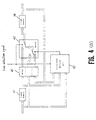
- Fig. 4(a) is a block diagram of an error concealment part 26a of the fifth embodiment, in which the parts 41 and 44 are 1-page memories each having capacity of storing 1 page data, 42 is a concealment decision part, 43 is a switch, and 45 is a delay.
- a block which has been transmitted or recorded and reproduced is first inputted to the 1-page memory 41.
- the concealment decision part 42 the block outputted from the 1-page memory 41, when an error is detected in the block, is subjected to judgement as to with which of the data in the reference block one page after that to be inputted or the data in the reference block one page before that to be outputted from the 1-page memory 44 has the stronger correlation of the data of the block.
- the switch 43 when no error has been'detected, the output of the 1-page memory 41 is selected, and when an error has been detected, the reference block of the page selected by the concealment decision part 42 is selected.
- the block selected with the switch 43 is outputted via the 1-page memory 44.
- the data in the block in which errors have been detected can be utilized in the concealment decision part 42.
- the block having the stronger correlation can be selected.
- the difference of the DC coefficients of the parallelepiped which is a unit of the bit rate reduction is taken between the block with which the error has been detected and each reference block, and, based on the respective absolute values, correlation detection operation is carried out by one block.
- a method of obtaining the sum of the absolute values of the differences of the DC coefficients by one block respectively is the simplest way. While the operation is carried out at the concealment detection part 42, the respective data are delayed in block unit by the delay 45.
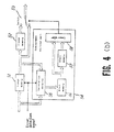
- Fig. 4(b) is a block diagram of the concealment part 26a of the sixth embodiment, in which the parts 51 and 52 are 1-page memories, 53 is a switch, 54 is a concealment decision part, 55 is a correlation detector, 56 and 57 are each a block memory, and 58 is a comparator.
- the block which has been transmitted or recorded and reproduced is first inputted to the 1-page memory 51. At this time, by selecting the block in which an error has been detected to "write-inhibit" state, the signal concealed by the reference block one page before is written in the 1-page memory 51. The signal is further transferred to the 1-page memory 52.
- the signal from the 1-page memory 51 is selected by using the switch 53.
- the signal from the 1-page memory 52 is selected by using the switch 53.
- the difference of the DC coefficient of the parallelepiped which is a unit of the bit rate reduction is taken between the signal from the 1-page memory 51 and the signal to be inputted, and, based on the respective absolute values, correlation detection operation is carried out by one block with correlation block with correlation detector 55. However, if an error has been detected with either block, the related information is written in the block memory 56.
- a method of obtaining the average of the absolute values of the differences of the DC coefficients by one block is the simplest way. And, the results thereof are written in the block memory 56 by block, and transferred to the block memory 57 on a page by page basis.
- the correlated information between the block near the block in which errors have been detected and the block near the reference block one page before it is read out from the block memory 57, and the information about correlation between the block near the block in which errors have been detected and the block near the reference block one page after it is read out from the block memory 56, and the respective correlated information is subjected to operation in consideration of the distance from the block in which the error has been detected, by which judgement is made as to with which reference block the correlation is stronger.
- the method of obtaining the average of the correlated information is the simplest.
- the data which are mutually near in space have strong correlation. Accordingly, when judgement is made on the data in the block lying near the block in which the error has been detected (e.g., adjacent block) as to with which of the blocks near the reference block one page before the block in which the error has been detected and the reference block one page after it, respectively, it becomes possible to select the reference block which has the strong correlation with the block in which the error has been detected.
- the block lying near the block in which the error has been detected e.g., adjacent block
- an operation to obtain the correlated information to be carried out with the correlation detector 55 is carried out on a page by page basis.
- the blocks are not to be used.
- the method of obtaining the average of the absolute values of the difference of DC coefficients by 1 block is the simplest.
- the result of said operation is written in the block memory 56 as the correlated information and transferred to the block memory 57 by page.
- the block memories 56 and 57 may be D-FF of the digit number sufficient for 1 operation result.
- the comparator 58 the correlated information between the page in which the error has been detected and the page before it is read out from the block memory 57, and the correlated information between the page in which the error has been detected and the page after it is read out from the block memory 56, and judgement is made as to with which reference block the correlation is stronger.
- the scene change as there is correlation on only either one of the screen one page before or one page after over all pages, it becomes possible to select more accurately the page having the strong correlation by judging the concealment method in page unit.
- Fig. 5(a) is a block diagram of an error concealment part 26a of another embodiment, in which the parts 61 and 67 are 1-page memories, 62 is a concealment information detector, 63 is a concealment decision part, 64 is a first switch, 65 is a second switch, 66 is a concealment information modifier, and 68 is a delay.
- the operation of the seventh embodiment is explained hereafter.
- the block which has been transmitted or recorded and reproduced is first inputted to the 1-page memory 61.
- the concealment information detector 62 the concealment information of the reference block one page after that to be inputted and the concealment information of the reference block one page before that outputted from the 1-page memory 67 are detected, and search is performed as to whether those reference blocks were previously concealed by the data in the block which is presently in process.
- the said block is selected as such by the second switch 65.
- the first switch 64 is controlled by the information outputted from the concealment information detector 62, so as to select with the second switch 65 the reference block so concealed, and if there is not the previously concealed block, judgement is made with the concealment decision part 63 as to with which of the data in the reference blocks of one page before or one page after the correlation is stronger, and the first switch 64 is controlled by the information outputted from the concealment information detector 62, so that the reference block having the stronger correlation is selected by the second switch 65.
- the block thus selected with the second switch 65 is inputted to the concealment information modifier 66.
- the concealment information modifier 66 modification of the concealment information is performed appropriately to store whether the block is concealed and in the case of concealment, with which reference block of the page (before or after) the concealment has been made.
- the output of the concealment information modifier 66 is also outputted through the 1-page memory 67.
- the data in the block in which errors have been detected in the concealment decision part 63 By comparing the data in the block one page before from the 1-page memory 67 with the data in the block one page after to be inputted and selecting the block in which there are a large number of the close data, the block having the stronger correlation can be selected. Comparison of data is performed in the similar manner to that in the concealment decision part 42 in the fifth embodiment.
- the delay 68 delays the respective data in block unit.
- Fig. 5(b) is a block diagram of an error concealment part 26a of another embodiment, in which the parts 71 and 72 are 1-page memories, 73 is a second switch, 74 is a concealment information modifier, 75 is a concealment information detector, 76 is a first switch, 77 is a concealment decision part, 78 is a correlation detector, 79 and 80 are block memories, and 81 is a comparator.
- the block which has been transmitted or recorded and reproduced is first inputted to the 1-page memory 71. At this time, the signal concealed by the reference block one page before by setting the block in which error has been detected to 'write inhibit', the concealed signal by the reference block one page before is written in the 1-page memory 71.
- This signal is further transferred to the 1-page memory 72.
- the signal from the 1-page memory 71 is selected by using the second switch 73.
- the signal from the 1-page memory 72 is selected by using the second switch 73.
- the concealment information detector 75 detects the concealment information in the reference block one page after that inputted to the 1-page memory 72 and the concealment information in the reference block one page before that outputted from the 1-page memory 72 with respect to the block in which error has been detected, and searches as to whether those reference blocks were previously concealed by the data of the block at present in process.
- the first switch 76 is controlled so as to select with the second switch 73 the reference block so concealed, and if there is not the previously concealed block, judgement is made with the concealment decision part 77 as to with which of the data in the reference blocks of one page before or one page after the correlation is stronger, and the first switch 76 is controlled so that the reference block having the stronger correlation is selected by the second switch 73.
- the block thus selected with the second switch 73 is inputted to the concealment information modifier 74.
- the concealment information modifier 74 Modiion is performed according to necessity so as to make it possible to show the condition whether the concealment information in each block is in the block in which the respective block is concealed, and in case of the concealment, with which reference block of the page (before or after) the concealment has been made.
- the concealment decision part 77 the difference of the DC coefficients of the parallelepiped which is a unit of the bit rate reduction is taken between the signal from the 1-page memory 71 and the signal to be inputted, and, based on the respective absolute values, correlation detection operation is carried out by one block with the correlation detector 78. However, if an error has been detected with either block, the related information is written in the block memory 79.
- a method of obtaining the average of the absolute values of the differences of the DC coefficients by one block is the simplest way. And, the results thereof are written in the block memory 79 by block, and transferred to the block memory 80 by page.
- the comparator 81 the correlated information of the block near the block in which errors have been detected and the block near the reference block one page before it is read out from the block memory 80, and the correlated information of the block near the block in which errors have been detected and the block near the reference block one page after it is read out from the block memory 79, and the respective correlated information is subjected to operation in consideration of the distance from the block in which the error has been detected, by which judgement is made as to with which reference block the correlation is stronger.
- the method of obtaining the average of the correlated information is the simplest.
- an operation to obtain the correlated information to be carried out with the correlation detector 78 is carried out by 1 page.
- the method of obtaining the average of the absolute values of the difference of DC coefficients by 1 block is the simplest.
- the result of said operation is written in the block memory 79 as the correlated information and transferred to the block memory 80 by page.
- the block memories 79 and 80 may be D-FF of the digit number sufficient for 1 operation result.
- the comparator 81 the correlated information between the page in which the error has been detected and the page before it is read out from the block memory 80, and the correlated information between the page in which the error has been detected and the page after it is read out from the block memory 79, and judgement is made as to with which reference block the correlation is stronger.
- This procedure can be the same as that of the concealment decision part 54 in the sixth embodiment.
- the fifth, sixth, seventh and eighth embodiments there may be used not only the DC coefficient of parallelepiped but also the low frequency coefficient for the comparative operation. Further, as a bit rate reduction, a method other than the orthogonal transformation may be applicable. In order to simplify the apparatus, it may be possible to restrict the concealment to a method of replacing at all times with a block one page before. By this method, detection of inter-page correlation becomes unnecessary, and it may suffice for the concealment information to be always detected only one page after.
- Fig. 6 is a block diagram of the correlation detectors 55 and 78 of the ninth embodiment, in which the parts 101 and 102 are the signal input parts, 103 is an inverter, 104 and 107 are adders, 105 is an absolute converter, 106 is an adaptive weighting circuit, 108 is an averaging circuit, 109 is a detection judger, and 110 is a counter.
- the signal of the n-th page is inputted from the signal input part 101, and the n+1-th page from the signal input part 102, and the difference between them is obtained by using the inverter 103 and adder 104, an absolute value is taken by the absolute converter 105, and linear addition is carried out by using an adaptive weighting circuit 106 and adder 107.
- judgement on the selection of the sample block is also carried out with the counter 110, by which the value obtained by controlling the linear addition with the adder 107 is used as the correlated information.
- This circuit constitution is an example.
- the signal on the n-th page and that on the n+1-th page may be inputted from either of the signal input parts 101 and 102.
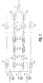
- Fig. 7 is a block diagram of the concealment decision parts 42 and 63 of the tenth embodiment, in which the parts 101, 102a, 102b are signal input parts, 103a and 103b are inverters, 104a, 104b, 107a, and 107b are adders,105a and 105b are absolute converters, 106a and 106b are adaptive weighting circuits, 108a and 108b are averaging circuits, 109a and 109b are detection judgers, 110a and 110b are counters, and 111 is a comparator.
- the signal on the n-th page is inputted from the signal 101, the signal on the n-1-th page from the signal input part 102a, and the signal on the n+1-th page from the signal input part 102b.
- the correlated information of the signals between the n-th page and the n-1-th page obtained by the averaging circuit 108a is compared with the correlated information of the signals between the n-th page and the n+1-th page obtained by the averaging circuit 108b and judgement is made that the smaller value one has the stronger correlation.
- the method of obtaining the respective correlated information is the same as in the ninth embodiment.
Landscapes
- Engineering & Computer Science (AREA)
- Multimedia (AREA)
- Signal Processing (AREA)
- Computer Security & Cryptography (AREA)
- Television Signal Processing For Recording (AREA)
- Compression Or Coding Systems Of Tv Signals (AREA)
Claims (21)
- Dispositif d'enregistrement et de reproduction de signal vidéo numérique comprenant :des moyens de codage (12a, 12b) destinés à soumettre un signal vidéo numérique d'entrée à un codage de réduction de débit binaire pour obtenir un premier signal vidéo codé à réduction de débit binaire ;des moyens de traitement de signal d'enregistrement (15a, 15b) comprenant des moyens de modulation destinés à moduler le premïer signal vidéo codé à réduction de débit binaire provenant desdits moyens de codage pour obtenir un signal vidéo modulé ;des moyens d'enregistrement et de reproduction (16a, 16b) destinés à enregistrer le signal vidéo modulé provenant desdits moyens de traitement de signal d'enregistrement sur un support d'enregistrement et destinés à reproduire le signal enregistré provenant dudit support d'enregistrement pour obtenir un signal vidéo modulé reproduit ;des moyens de démodulation (17, 17b) destinés à démoduler le signal modulé reproduit pour obtenir un signal codé à réduction de débit binaire reproduit ;des moyens de correction et de dissimulation d'erreur (18a, 18b) destinés à détecter des erreurs du signal codé à réduction de débit binaire reproduit qui contiennent des erreurs corrigibles et des erreurs non-corrigibles, lesdits moyens de correction et de dissimulation d'erreur corrigeant lesdites erreurs corrigibles et dissimulant lesdites erreurs non-corrigibles pour obtenir un signal vidéo codé dans lequel les erreurs ont été corrigées ou dissimulées ;des moyens de décodage (20a, 20b) destinés à décoder le signal vidéo codé obtenu à partir desdits moyens de correction et de dissimulation d'erreur pour obtenir un signal vidéo numérique reproduit,caractérisé en ce qu'il comprend, de plus :des moyens d'entrée de copie (13a, 13b) destinés à entrer, comme signal d'entrée de copie, un second signal vidéo codé à réduction de débit binaire fourni à partir de l'extérieur dudit dispositif ;des moyens de sélection (14a, 14b) destinés à sortir, de manière sélective, soit ledit premier signal vidéo codé à réduction de débit binaire provenant desdits moyens de codage, soit ledit second signal vidéo codé à réduction de débit binaire provenant desdits moyens d'entrée de copie et destinés à fournir un signal vidéo codé à réduction de débit binaire sélectionné auxdits moyens de traitement de signal d'enregistrement, de sorte que lesdits moyens de modulation modulent le signal vidéo codé à réduction de débit binaire sélectionné provenant desdits moyens de sélection pour obtenir le signal vidéo modulé ; etdes moyens de sortie de copie (19a, 19b) destinés à sortir le signal vidéo codé obtenu à partir desdits moyens de correction et de dissimulation d'erreur comme signal de sortie de copie.
- Dispositif selon la revendication 1, dans lequel lesdits moyens de traitement de signal d'enregistrement comprennent des moyens (31b) destinés à ajouter des données auxiliaires spécifiques au signal vidéo codé à réduction de débit binaire provenant desdits moyens de sélection, de sorte que lesdites données auxiliaires soient enregistrées et reproduites avec le signal vidéo codé à réduction de débit binaire et dans lequel lesdits moyens de sortie de copie sortent des données auxiliaires reproduites avec le signal vidéo codé provenant desdits moyens de correction d'erreur.
- Dispositif selon la revendication 1, dans lequel ledit second signal vidéo codé à réduction de débit binaire contient un code de correction d'erreur et lesdits moyens d'entrée de copie comprennent des moyens destinés à décoder ledit code de correction d'erreur.
- Dispositif selon la revendication 1, dans lequel lesdits moyens de sortie de copie (19a, 19b) comprennent des moyens (19a, 19b) destinés à soumettre le signal vidéo codé, à sortir comme signal de sortie de copie, à un codage à correction d'erreur pour obtenir un signal de sortie de copie contenant un code de correction d'erreur.
- Dispositif selon la revendication 1, dans lequel lesdits moyens de traitement de signal d'enregistrement (15a, 15b) comprennent des moyens (31, 32) destinés à ajouter au signal vidéo codé à réduction de débit binaire provenant desdits moyens de sélection des informations de protection de copie indiquant une condition de protection de copie du signal vidéo codé à réduction de débit binaire.
- Dispositif selon la revendication 1, dans lequel ledit second signal vidéo codé à réduction de débit binaire contient des informations de protection de copie indiquant une condition de protection de copie du second signal vidéo codé à réduction de débit binaire et dans lequel lesdits moyens de traitement de signal d'enregistrement (15a, 15b) comprennent des moyens (31, 32) destinés à modifier lesdites informations de protection de copie.
- Dispositif selon la revendication 1, dans lequel lesdits moyens de correction et de dissimulation d'erreur (18a, 18b) comprennent :des moyens de correction d'erreur (25a) destinés à détecter et corriger des erreurs du signal codé à réduction de débit binaire reproduit pour obtenir un signal vidéo codé à erreur corrigée dans lequel une erreur non-corrigible a été détectée, mais n'a pas été corrigée ; etdes moyens de dissimulation d'erreur (26a) destinés à dissimuler ladite erreur non-corrigible contenue dans le signal vidéo codé à erreur corrigée provenant desdits moyens de correction d'erreur pour obtenir un signal vidéo codé à erreur dissimulée.
- Dispositif selon la revendication 7, dans lequel lesdits moyens de codage (12a, 12b) divisent un signal vidéo numérique d'entrée de chaque page constituée d'un ou plusieurs champs en blocs et soumettent le signal vidéo numérique d'entrée à un codage de réduction de débit binaire sur une base bloc par bloc pour obtenir le signal vidéo codé à réduction de débit binaire.
- Dispositif selon la revendication 8, dans lequel lorsqu'un bloc avec erreurs est traité dans lequel une erreur non-corrigible a été détectée et n'a pas été corrigée, ledit bloc avec erreurs est inclus tel quel dans le signal vidéo codé obtenu à partir desdits moyens de correction d'erreur.
- Dispositif selon la revendication 9, dans lequel lesdits moyens de dissimulation d'erreur (26a) comprennent :des moyens de décision de bloc de référence (42 ; 54 ; 63 ; 77), couplés à la sortie desdits moyens de correction d'erreur agencés pour utiliser les blocs de référence pour vérifier les corrélations des données dans ledit bloc avec erreurs avec les données dans un premier bloc de référence à une position correspondante sur une page précédente et les données dans un second bloc de référence qui se trouve à une position correspondante sur une page suivante, pour décider lequel des premier et second blocs de référence a une corrélation plus forte avec le bloc avec erreurs que l'autre, et pour sortir un signal de décision de bloc indicatif de l'un des premier et second blocs de référence qui a la plus forte corrélation avec le bloc avec erreurs que l'autre ; etdes moyens de remplacement (43, 53, 65, 73) sensibles au signal de décision de bloc pour remplacer le bloc avec erreurs par le bloc de référence indiqué par le signal de décision de bloc pour obtenir, de ce fait, un signal vidéo codé à erreur dissimulée.
- Dispositif selon la revendication 10, dans lequel lesdits moyens de traitement de signal d'enregistrement (15a, 15b) comprennent des moyens destinés à ajouter au signal vidéo codé à réduction de débit binaire des données de dissimulation indiquant si, oui ou non, un bloc est un bloc dissimulé qui a été remplacé par un autre bloc, et le bloc par lequel le bloc dissimulé a été remplacé, de sorte queledit signal codé à réduction de débit binaire reproduit comprenne des informations de dissimulation reproduites et,dans lequel lesdits moyens de correction et de dissimulation d'erreur (18a, 18b) comprennent en outre :des moyens de détection de bloc dissimulé (62, 75) couplés auxdits moyens de correction d'erreur (25a) destinés à détecter, à partir des informations de dissimulation reproduites de blocs précédents, lequel ledit bloc avec erreurs pourrait avoir remplacé, si ledit bloc avec erreurs est ou non un bloc par lequel un autre bloc a été remplacé et quel bloc a été remplacé par ledit bloc avec erreurs, et destinés à sortir un signal de détection de bloc indiquant si, oui ou non, ledit bloc avec erreurs a remplacé un autre bloc et, si ledit bloc avec erreurs a remplacé un autre bloc, un bloc qui a été remplacé par ledit bloc avec erreurs, et dans lequel lesdits moyens de remplacement comprennent, de plus, des moyens de sélection (64 ; 76) sensibles audit signal de détection de bloc, agencés de telle sorte que lesdits moyens de remplacement remplacent le bloc avec erreurs par le bloc indiqué par ledit signal de détection de bloc lorsque le bloc avec erreurs a remplacé un autre bloc et remplacent le bloc avec erreurs par ledit bloc de référence indiqué par ledit signal de décision de bloc lorsque le bloc avec erreurs n'a pas remplacé un autre bloc.
- Dispositif selon les revendications 10 ou 11, dans lequel lesdits moyens de décision de bloc de référence (42 ; 54 ; 63 ; 77) comprennent des moyens (55 ; 78) destinés à vérifier la corrélation entre les données dans ledit bloc avec erreurs et dans lesdits blocs de référence en calculant les corrélations entre un ou plusieurs premiers blocs de référence sur la même page comme ledit bloc avec erreurs et d'autres blocs de référence dans des positions correspondantes sur les pages précédente et suivante.
- Dispositif selon la revendication 12, dans lequel ledit bloc de référence sur la même page que ledit bloc avec erreurs est ledit bloc avec erreurs et lesdits autres blocs de référence comprennent lesdits blocs remplacés.
- Dispositif selon la revendication 12, dans lequel ledit premier bloc de référence est un bloc contigu audit bloc avec erreurs.
- Dispositif selon la revendication 12, dans lequel lesdits premiers blocs de référence sont des blocs contigus audit bloc avec erreurs.
- Dispositif selon l'une des revendications 14 ou 15, dans lequel tous lesdits blocs de référence sont des blocs sans erreurs.
- Le dispositif selon la revendication 12, dans lequel lesdits premiers blocs de référence sont tous les blocs sur la page avec ledit bloc avec erreurs dans lesquels aucune erreur n'a été détectée et aucune erreur n'a été détectée dans les blocs correspondants sur lesdites pages précédente et suivante.
- Dispositif selon l'une quelconque des revendications 12 ou 17, dans lequel lesdits moyens de codage (12a, 12b) divisent un signal vidéo numérique dans chaque bloc en composantes basse fréquence et en composantes haute fréquence.
- Dispositif selon la revendication 18, dans lequel lesdits moyens (55, 78) comparent les composantes basse fréquence dans le ou les premiers blocs de référence et les composantes basse fréquence dans les autres blocs de référence pour détecter, de ce fait, la corrélation entre le bloc avec erreurs et chacun desdits premiers et autres blocs de référence.
- Dispositif selon la revendication 19, dans lequel lesdits moyens de décision de bloc de référence (42, 54, 63, 77) comprennent, de plus, des moyens (111) destinés à comparer une somme des valeurs absolues des différences entre les composantes basse fréquence dans le ou les premiers blocs de référence et les composantes basse fréquence dans l'autre ou les autres blocs de référence sur la page précédente et une somme des valeurs absolues des différences entre les composantes basse fréquence dans le ou les premiers blocs de référence et les composantes basse fréquence dans l'autre ou les autres blocs de référence sur la page suivante, et
destinés à sélectionner l'un des premiers et des autres blocs de référence associé à la page qui donne la plus petite valeur des sommes. - Dispositif selon la revendication 19, dans lequel lesdits moyens de décision de bloc de référence (42, 54, 63, 77) comprennent, de plus, des moyens (111) destinés à comparerune moyenne des valeurs absolues des différences entre les composantes basse fréquence dans le ou les premiers blocs de référence et les composantes basse fréquence dans l'autre ou les autres blocs de référence sur la page précédente ; etune moyenne des valeurs absolues des différences entre les composantes basse fréquence dans le ou les premiers blocs de référence et les composantes basse fréquence dans l'autre ou les autres blocs de référence sur la page suivante ; etdestinés à sélectionner l'un des premiers et des autres blocs de référence associé à la page qui donne la plus petite valeur des moyennes.
Applications Claiming Priority (4)
| Application Number | Priority Date | Filing Date | Title |
|---|---|---|---|
| JP221978/89 | 1989-08-29 | ||
| JP22197889A JP2636431B2 (ja) | 1989-08-29 | 1989-08-29 | 誤り修正装置及び誤り修正方法 |
| JP173429/90 | 1990-06-29 | ||
| JP2173429A JP2815467B2 (ja) | 1990-06-29 | 1990-06-29 | ディジタル映像信号記録再生装置及び記録再生方法 |
Publications (3)
| Publication Number | Publication Date |
|---|---|
| EP0415699A2 EP0415699A2 (fr) | 1991-03-06 |
| EP0415699A3 EP0415699A3 (en) | 1992-05-27 |
| EP0415699B1 true EP0415699B1 (fr) | 1997-07-23 |
Family
ID=26495406
Family Applications (1)
| Application Number | Title | Priority Date | Filing Date |
|---|---|---|---|
| EP90309378A Expired - Lifetime EP0415699B1 (fr) | 1989-08-29 | 1990-08-28 | Dispositif d'enregistrement et de reproduction d'un signal vidéo numérique |
Country Status (3)
| Country | Link |
|---|---|
| US (1) | US5193010A (fr) |
| EP (1) | EP0415699B1 (fr) |
| DE (1) | DE69031102T2 (fr) |
Families Citing this family (27)
| Publication number | Priority date | Publication date | Assignee | Title |
|---|---|---|---|---|
| EP0465110A3 (en) * | 1990-06-27 | 1993-08-11 | Matsushita Electric Industrial Co., Ltd. | Apparatus for record and playback of a digital signal |
| JP2890740B2 (ja) * | 1990-08-09 | 1999-05-17 | 松下電器産業株式会社 | ディジタル映像信号再生装置 |
| JPH0498987A (ja) * | 1990-08-16 | 1992-03-31 | Matsushita Electric Ind Co Ltd | 誤り修整方法 |
| EP0492528B1 (fr) * | 1990-12-27 | 1996-10-09 | Kabushiki Kaisha Toshiba | Appareil d'enregistrement et de reproduction |
| EP0744869B1 (fr) * | 1990-12-28 | 2000-03-22 | Canon Kabushiki Kaisha | Appareil de traitement d'image |
| DE69225346T2 (de) * | 1991-02-07 | 1998-09-03 | Matsushita Electric Ind Co Ltd | Verfahren und Vorrichtung zur Übertragung und Reproduktion von einem digitalen Signal |
| US5621578A (en) * | 1992-02-06 | 1997-04-15 | Matsushita Electric Industrial Co., Ltd. | Method of transmitting digital video and audio signals between bit rate reduction encoded signal recording and reproducing systems |
| US5313471A (en) * | 1991-02-26 | 1994-05-17 | Matsushita Electric Industrial Co., Ltd. | Error concealing method |
| US5146325A (en) * | 1991-04-29 | 1992-09-08 | Rca Thomson Licensing Corporation | Video signal decompression apparatus for independently compressed even and odd field data |
| US5208666A (en) * | 1991-10-25 | 1993-05-04 | Tektronix, Inc. | Error detection for digital television equipment |
| US5400076A (en) * | 1991-11-30 | 1995-03-21 | Sony Corporation | Compressed motion picture signal expander with error concealment |
| JPH05244468A (ja) * | 1992-02-28 | 1993-09-21 | Mitsubishi Electric Corp | 画像受信装置 |
| JP2962053B2 (ja) * | 1992-06-25 | 1999-10-12 | 松下電器産業株式会社 | 信号処理装置 |
| US5581360A (en) * | 1992-06-17 | 1996-12-03 | Sony Corporation | Methods and systems for dubbing a variable-length encoded digital video signal on a record medium |
| JPH065015A (ja) * | 1992-06-18 | 1994-01-14 | Canon Inc | 記録再生装置、記録装置及び再生装置 |
| US5589994A (en) * | 1992-08-21 | 1996-12-31 | Mitsubishi Denki Kabushiki Kaisha | Image recording method and apparatus with reduced error propagation |
| JP3158740B2 (ja) * | 1992-11-20 | 2001-04-23 | ソニー株式会社 | ディジタルビデオ信号の送信方法及びダビング方法 |
| US5532837A (en) * | 1992-12-18 | 1996-07-02 | Matsushita Electric Industrial Co., Ltd. | Digital video signal processing apparatus |
| JPH06205386A (ja) * | 1992-12-28 | 1994-07-22 | Canon Inc | 画像再生装置 |
| KR100261072B1 (ko) * | 1993-04-30 | 2000-07-01 | 윤종용 | 디지털 신호처리시스템 |
| WO1995003674A1 (fr) * | 1993-07-19 | 1995-02-02 | British Telecommunications Public Limited Company | Detection d'erreurs dans des images video |
| JP3428697B2 (ja) * | 1993-09-07 | 2003-07-22 | キヤノン株式会社 | 画像復号化方法 |
| US6075918A (en) * | 1995-10-26 | 2000-06-13 | Advanced Micro Devices, Inc. | Generation of an intermediate video bitstream from a compressed video bitstream to enhance playback performance |
| US5768536A (en) * | 1995-10-26 | 1998-06-16 | Advanced Micro Devices, Inc. | Generation of a secondary video bitstream from a compressed video bitstream to enhance playback performance |
| KR100189534B1 (ko) * | 1996-06-27 | 1999-06-01 | 윤종용 | 비트 에러레이트를 이용한 디지탈 영상기록 재생장치의 트랙킹 제어회로 및 그 제어방법 |
| US7168026B2 (en) * | 2001-06-22 | 2007-01-23 | Intel Corporation | Method and apparatus for preservation of failure state in a read destructive memory |
| JP2004062950A (ja) * | 2002-07-25 | 2004-02-26 | Sony Corp | データ処理装置およびデータ処理方法、並びにプログラム |
Family Cites Families (7)
| Publication number | Priority date | Publication date | Assignee | Title |
|---|---|---|---|---|
| GB2140189B (en) * | 1983-05-19 | 1986-04-30 | Sony Corp | Digital video tape recorder apparatus |
| EP0232417B1 (fr) * | 1985-10-02 | 1991-11-06 | Deutsche Thomson-Brandt GmbH | Procede pour corriger les erreurs de transmission |
| JP2597987B2 (ja) * | 1986-02-08 | 1997-04-09 | ソニー株式会社 | ブロツク化伝送信号のデコード装置 |
| JP2557624B2 (ja) * | 1986-03-17 | 1996-11-27 | 株式会社 日立メディコ | デイジタルデ−タ記録再生装置 |
| JPS6367036A (ja) * | 1986-09-08 | 1988-03-25 | Matsushita Electric Ind Co Ltd | デイジタルデ−タ修整装置 |
| JPH01194691A (ja) * | 1988-01-29 | 1989-08-04 | Hitachi Ltd | ディジタル画像信号の記録再生装置 |
| JP2750717B2 (ja) * | 1988-12-15 | 1998-05-13 | 国際電信電話 株式会社 | 画像伝送誤り訂正方式 |
-
1990
- 1990-08-28 DE DE69031102T patent/DE69031102T2/de not_active Expired - Fee Related
- 1990-08-28 EP EP90309378A patent/EP0415699B1/fr not_active Expired - Lifetime
- 1990-08-28 US US07/574,288 patent/US5193010A/en not_active Expired - Lifetime
Also Published As
| Publication number | Publication date |
|---|---|
| US5193010A (en) | 1993-03-09 |
| DE69031102T2 (de) | 1998-01-15 |
| DE69031102D1 (de) | 1997-08-28 |
| EP0415699A3 (en) | 1992-05-27 |
| EP0415699A2 (fr) | 1991-03-06 |
Similar Documents
| Publication | Publication Date | Title |
|---|---|---|
| EP0415699B1 (fr) | Dispositif d'enregistrement et de reproduction d'un signal vidéo numérique | |
| US5142537A (en) | Video signal processing circuit | |
| EP0540350B1 (fr) | Méthode et dispositif pour codage à longueur variable | |
| US7317738B2 (en) | Data transmission method for embedded data, data transmitting and reproducing apparatuses and information recording medium therefor | |
| EP0617558B1 (fr) | Appareil pour dissimuler des erreurs de données | |
| US5481554A (en) | Data transmission apparatus for transmitting code data | |
| US5410553A (en) | Error concealment control method and device of digital video signal | |
| US5589994A (en) | Image recording method and apparatus with reduced error propagation | |
| EP0471580B1 (fr) | Méthode de masquage pour signal vidéo | |
| GB2265046A (en) | Digital recording and reproducing | |
| US6031959A (en) | Television signal recording and reproducing apparatus | |
| US5392129A (en) | Digital VCR signal processing apparatus for concealing uncorrectable errors | |
| US5805469A (en) | Digital audio signal processing apparatus and method for error concealment | |
| US5740187A (en) | Data processing using interpolation of first and second information based on different criteria | |
| US5384665A (en) | Data dividing apparatus | |
| EP0553817A2 (fr) | Appareil de transfert d'informations digitales | |
| JP3360868B2 (ja) | 映像データ処理装置及び方法 | |
| US6219157B1 (en) | Image coding apparatus | |
| JP3207739B2 (ja) | 画像再生装置 | |
| JP3291785B2 (ja) | ブロック変換符号化データの伝送装置 | |
| KR100213421B1 (ko) | 착오정정부호화 수단을 가진 기록장치 | |
| JP3282245B2 (ja) | ブロック符号化におけるエラー修整装置 | |
| JP3291371B2 (ja) | ブロック識別信号処理装置 | |
| JP3854688B2 (ja) | 画像処理装置、画像処理方法及びコンピュータ読み取り可能な記録媒体 | |
| JP3063675B2 (ja) | 映像信号の再生装置 |
Legal Events
| Date | Code | Title | Description |
|---|---|---|---|
| PUAI | Public reference made under article 153(3) epc to a published international application that has entered the european phase |
Free format text: ORIGINAL CODE: 0009012 |
|
| AK | Designated contracting states |
Kind code of ref document: A2 Designated state(s): DE FR GB NL |
|
| PUAL | Search report despatched |
Free format text: ORIGINAL CODE: 0009013 |
|
| AK | Designated contracting states |
Kind code of ref document: A3 Designated state(s): DE FR GB NL |
|
| 17P | Request for examination filed |
Effective date: 19921030 |
|
| 17Q | First examination report despatched |
Effective date: 19941110 |
|
| GRAG | Despatch of communication of intention to grant |
Free format text: ORIGINAL CODE: EPIDOS AGRA |
|
| GRAH | Despatch of communication of intention to grant a patent |
Free format text: ORIGINAL CODE: EPIDOS IGRA |
|
| GRAH | Despatch of communication of intention to grant a patent |
Free format text: ORIGINAL CODE: EPIDOS IGRA |
|
| GRAA | (expected) grant |
Free format text: ORIGINAL CODE: 0009210 |
|
| AK | Designated contracting states |
Kind code of ref document: B1 Designated state(s): DE FR GB NL |
|
| REF | Corresponds to: |
Ref document number: 69031102 Country of ref document: DE Date of ref document: 19970828 |
|
| ET | Fr: translation filed | ||
| PLBE | No opposition filed within time limit |
Free format text: ORIGINAL CODE: 0009261 |
|
| STAA | Information on the status of an ep patent application or granted ep patent |
Free format text: STATUS: NO OPPOSITION FILED WITHIN TIME LIMIT |
|
| 26N | No opposition filed | ||
| REG | Reference to a national code |
Ref country code: GB Ref legal event code: IF02 |
|
| PGFP | Annual fee paid to national office [announced via postgrant information from national office to epo] |
Ref country code: DE Payment date: 20070823 Year of fee payment: 18 |
|
| PGFP | Annual fee paid to national office [announced via postgrant information from national office to epo] |
Ref country code: GB Payment date: 20070822 Year of fee payment: 18 |
|
| PGFP | Annual fee paid to national office [announced via postgrant information from national office to epo] |
Ref country code: NL Payment date: 20070815 Year of fee payment: 18 |
|
| PGFP | Annual fee paid to national office [announced via postgrant information from national office to epo] |
Ref country code: FR Payment date: 20070808 Year of fee payment: 18 |
|
| GBPC | Gb: european patent ceased through non-payment of renewal fee |
Effective date: 20080828 |
|
| NLV4 | Nl: lapsed or anulled due to non-payment of the annual fee |
Effective date: 20090301 |
|
| PG25 | Lapsed in a contracting state [announced via postgrant information from national office to epo] |
Ref country code: NL Free format text: LAPSE BECAUSE OF NON-PAYMENT OF DUE FEES Effective date: 20090301 |
|
| REG | Reference to a national code |
Ref country code: FR Ref legal event code: ST Effective date: 20090430 |
|
| PG25 | Lapsed in a contracting state [announced via postgrant information from national office to epo] |
Ref country code: FR Free format text: LAPSE BECAUSE OF NON-PAYMENT OF DUE FEES Effective date: 20080901 Ref country code: DE Free format text: LAPSE BECAUSE OF NON-PAYMENT OF DUE FEES Effective date: 20090303 |
|
| PG25 | Lapsed in a contracting state [announced via postgrant information from national office to epo] |
Ref country code: GB Free format text: LAPSE BECAUSE OF NON-PAYMENT OF DUE FEES Effective date: 20080828 |