EP0415839A2 - Connecteur à fibre optique - Google Patents
Connecteur à fibre optique Download PDFInfo
- Publication number
- EP0415839A2 EP0415839A2 EP90402371A EP90402371A EP0415839A2 EP 0415839 A2 EP0415839 A2 EP 0415839A2 EP 90402371 A EP90402371 A EP 90402371A EP 90402371 A EP90402371 A EP 90402371A EP 0415839 A2 EP0415839 A2 EP 0415839A2
- Authority
- EP
- European Patent Office
- Prior art keywords
- ferrule
- optical fiber
- distance
- connector
- stopper
- Prior art date
- Legal status (The legal status is an assumption and is not a legal conclusion. Google has not performed a legal analysis and makes no representation as to the accuracy of the status listed.)
- Withdrawn
Links
- 239000013307 optical fiber Substances 0.000 title claims abstract description 24
- 230000006835 compression Effects 0.000 claims 1
- 238000007906 compression Methods 0.000 claims 1
- 230000003287 optical effect Effects 0.000 abstract description 4
- 238000010276 construction Methods 0.000 description 7
- 230000008878 coupling Effects 0.000 description 5
- 238000010168 coupling process Methods 0.000 description 5
- 238000005859 coupling reaction Methods 0.000 description 5
- 230000000881 depressing effect Effects 0.000 description 3
- 239000000853 adhesive Substances 0.000 description 1
- 230000001070 adhesive effect Effects 0.000 description 1
- 239000000919 ceramic Substances 0.000 description 1
- 230000000694 effects Effects 0.000 description 1
- 229910001220 stainless steel Inorganic materials 0.000 description 1
- 239000010935 stainless steel Substances 0.000 description 1
Images


Classifications
-
- G—PHYSICS
- G02—OPTICS
- G02B—OPTICAL ELEMENTS, SYSTEMS OR APPARATUS
- G02B6/00—Light guides; Structural details of arrangements comprising light guides and other optical elements, e.g. couplings
- G02B6/24—Coupling light guides
- G02B6/36—Mechanical coupling means
- G02B6/38—Mechanical coupling means having fibre to fibre mating means
- G02B6/3807—Dismountable connectors, i.e. comprising plugs
- G02B6/381—Dismountable connectors, i.e. comprising plugs of the ferrule type, e.g. fibre ends embedded in ferrules, connecting a pair of fibres
- G02B6/3818—Dismountable connectors, i.e. comprising plugs of the ferrule type, e.g. fibre ends embedded in ferrules, connecting a pair of fibres of a low-reflection-loss type
- G02B6/3821—Dismountable connectors, i.e. comprising plugs of the ferrule type, e.g. fibre ends embedded in ferrules, connecting a pair of fibres of a low-reflection-loss type with axial spring biasing or loading means
-
- G—PHYSICS
- G02—OPTICS
- G02B—OPTICAL ELEMENTS, SYSTEMS OR APPARATUS
- G02B6/00—Light guides; Structural details of arrangements comprising light guides and other optical elements, e.g. couplings
- G02B6/24—Coupling light guides
- G02B6/36—Mechanical coupling means
- G02B6/38—Mechanical coupling means having fibre to fibre mating means
- G02B6/3807—Dismountable connectors, i.e. comprising plugs
- G02B6/3869—Mounting ferrules to connector body, i.e. plugs
Definitions
- the present invention relates to an optical fiber connector using a precise ferrule.
- Such known optical fiber connectors have construction generally as shown in Fig. 7.
- Such known construction comprises an optical fiber 20 fixed at the center of ferrule 30, which is housed in a connector sleeve 40 being axially movable and a compressive spring 50 is arranged between the bottom of the connector sleeve 40 and the ferrule 30.
- the ferrule 30 is in general column shape and the connector sleeve 40 is in general cylindrical shape.
- Fig. 7 and other figures show the connector just schematically and parts not relating to the present invention are omitted and the size of various parts may be exaggerated to give an easy understanding of the invention.
- Jointing between the connector sleeves 40A and 40B and the adaptor 60 is effected by a bayonet coupling, a screw coupling and other jointing means.
- optical connection is substantially interrupted.
- the present invention has for its object to solve the abovementioned problems.
- the present invention is to realize an optical fiber connector in which even either of the ferrule 30A or 30B moved backward by depressing the spring 50, the optical connection is not interrupted.
- the maximum amount of constriction D is arranged less than the double value of the amount of constriction d at the time of abutting connection. According to this construction, the amount of movement of ferrule when the optical fiber cord 20 is pulled backwards is less than the maximum amount of follow-up forward movement of the other ferrule. Thus there will be no chance in that a clearance is caused between the abutting surface of the ferrule and hence there will be no fear the optical connection is disconnected.
- the maximum amount D of constriction of the spring 50 inside the optical fiber connector being less than double (2d) of the constriction amount d is realized in practice as follows.
- a stopper step portion 34 is provided on the ferrule 30, which stopper step portion 34 having a stopper surface facing against the bottom 42 of the connector sleeve 40 and the distance between the bottom surface 42 of the connector sleeve 40 and the distance between the bottom surface 42 of the connector sleeve 40 and the stopper step portion 34 is made equal to D, wherein (D ⁇ 2d).
- the ferrule 30 can not move backwardly relative to the connector sleeve more than the above distance D so that the spring 50 is not constrained more than the amount D.
- the ferrule 30 is in most of the cases formed as cylindrical shape or rectangular column shape provided with a fine hole for passing through the optical fiber along the center axis.
- the stopper step portion 34 is preferably provided along the whole periphery of cylindrical shape or the like.
- even a part of the stopper step portion is lacked, as far as the function as a stopper is effective, such model may be included in the scope of the present invention.
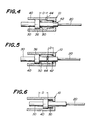
- a stopper sleeve 62 is mounted on the ferrule 30 to rest between its flange 36 and the bottom 42 of the connector sleeve 40 so as to form a gap corresponding to the distance D ( ⁇ 2d) between the bottom 42 of the connector sleeve 40.
- the outer diameter of the stopper sleeve 62 is made smaller than the inner diameter of the coil spring 50 so as not to interfere the spring action 26 of the coil spring 50.
- the stopper sleeve is fixed in its position against the ferrule 30 as shown in Fig. 3, however, it functions properly as well as the case that the stopper sleeve is not fixed its position. Accordingly, such embodiment of non-fixing the stopper sleeve is also included in the scope of the present invention.
- a stopper step portion 44 having the stopper surface against the flange 36 is provided near the bottom portion 42 of the connector sleeve 40.
- the interval between the stopper step portion 44 and the flange 36 is made equal to the amount D ( ⁇ 2d).
- a stopper ring 64 formed of C-shape ring is mounted on the shaft of ferrule 30 and the interval between the stopper ring 64 and the bottom 42 of the connector sleeve 40 is made equal to D ( ⁇ 2d).
- a groove is provided on the ferrule to mate with the C-shape ring 64 and fixed it.
- the invention is not limited to this construction. The necessary condition is to fix the stopper ring 64 not to move in axial direction of the ferrule 30.
- the stopper C-shape ring 64 may be fixed by using adhesive to the ferrule 30.
- this embodiment can be realized by arranging and selecting the height of the spring 50 when it is fully constrained and all the spring wire elements come in contact with each other so as not allow further constriction, to be related to said maximum amount D.
- this can be realized by selecting the height of the compressing spring 50 at its fully constrained condition, to be equal to an amount of the distance between the bottom 42 of the sleeve 40 and the flange 36 deducted by the distance D.
Landscapes
- Physics & Mathematics (AREA)
- General Physics & Mathematics (AREA)
- Optics & Photonics (AREA)
- Mechanical Coupling Of Light Guides (AREA)
Applications Claiming Priority (2)
| Application Number | Priority Date | Filing Date | Title |
|---|---|---|---|
| JP102155/89 | 1989-08-31 | ||
| JP1989102155U JPH0746885Y2 (ja) | 1989-08-31 | 1989-08-31 | 光コネクタ |
Publications (2)
| Publication Number | Publication Date |
|---|---|
| EP0415839A2 true EP0415839A2 (fr) | 1991-03-06 |
| EP0415839A3 EP0415839A3 (en) | 1992-03-04 |
Family
ID=14319841
Family Applications (1)
| Application Number | Title | Priority Date | Filing Date |
|---|---|---|---|
| EP19900402371 Withdrawn EP0415839A3 (en) | 1989-08-31 | 1990-08-27 | Optical fiber connector |
Country Status (4)
| Country | Link |
|---|---|
| US (1) | US5011258A (fr) |
| EP (1) | EP0415839A3 (fr) |
| JP (1) | JPH0746885Y2 (fr) |
| CA (1) | CA2023879A1 (fr) |
Cited By (3)
| Publication number | Priority date | Publication date | Assignee | Title |
|---|---|---|---|---|
| US7116882B2 (en) | 2002-07-16 | 2006-10-03 | Tyco Electronics Raychem Nv | Device for cleaving an optical fibre |
| WO2014195242A1 (fr) * | 2013-06-05 | 2014-12-11 | Reichle & De-Massari Ag | Dispositif de connexion enfichable |
| EP3379312A4 (fr) * | 2016-01-29 | 2019-07-10 | Fujikura Ltd. | Connecteur optique et système de connecteur optique |
Families Citing this family (8)
| Publication number | Priority date | Publication date | Assignee | Title |
|---|---|---|---|---|
| US5157749A (en) * | 1984-06-08 | 1992-10-20 | Amp Incorporated | High precision optical fiber connectors |
| US5179608A (en) * | 1990-09-28 | 1993-01-12 | Adc Telecommunications, Inc. | Connector for optical fiber |
| US5239604A (en) * | 1991-01-31 | 1993-08-24 | Adc Telecommunications, Inc. | Optical fiber crimp |
| US5159655A (en) * | 1991-01-31 | 1992-10-27 | Adc Telecommunications, Inc. | Optical fiber crimp |
| US5285510A (en) * | 1992-12-15 | 1994-02-08 | The Whitaker Corporation | Fiber optic connector |
| US5408558A (en) * | 1993-10-21 | 1995-04-18 | Litecom, Inc. | Connecting system with cleaved fiber and crimp termination |
| US6591056B1 (en) | 2000-03-30 | 2003-07-08 | Delphi Technologies, Inc. | Connector terminus springs |
| CN110735568B (zh) * | 2019-11-25 | 2024-11-12 | 广东东箭汽车科技股份有限公司 | 拉线传动系统及汽车 |
Family Cites Families (18)
| Publication number | Priority date | Publication date | Assignee | Title |
|---|---|---|---|---|
| US4798440A (en) * | 1983-01-24 | 1989-01-17 | Amp Incorporated | Fiber optic connector assembly |
| JPS59147308A (ja) * | 1983-02-14 | 1984-08-23 | Yazaki Corp | 光フアイバ−接続用コネクタ |
| US4747658A (en) * | 1983-03-14 | 1988-05-31 | International Telephone And Telegraph Corporation | Fiber optic contact |
| US4518220A (en) * | 1983-03-30 | 1985-05-21 | Gte Products Corporation | Fiber optic drawer connector assembly |
| FR2564210B1 (fr) * | 1984-05-11 | 1988-06-03 | Radiall Ind | Procede de blocage mecanique d'un element interieur dans un corps exterieur et application de ce procede a la realisation d'un embout de connecteur de fibre optique |
| JPH0627884B2 (ja) * | 1984-07-20 | 1994-04-13 | 日本電気株式会社 | 光コネクタ |
| US4787701A (en) * | 1984-11-13 | 1988-11-29 | Raychem Corp. | Optical fiber contact assembly |
| JPH0521044Y2 (fr) * | 1985-01-29 | 1993-05-31 | ||
| US4735480A (en) * | 1985-11-20 | 1988-04-05 | Raychem Corp. | Optical fiber connector |
| JPS62124513A (ja) * | 1985-11-25 | 1987-06-05 | Toshiba Corp | 光コネクタ |
| US4714317A (en) * | 1986-04-14 | 1987-12-22 | Siecor Corporation | Biconic optical fiber connector/attenuator |
| JPS63115115A (ja) * | 1986-10-31 | 1988-05-19 | Sumitomo Electric Ind Ltd | 光コネクタ |
| US4852963A (en) * | 1987-06-30 | 1989-08-01 | American Telephone And Telegraph Company, At&T Bell Laboratories | Optical fiber biconic connector |
| US4812009A (en) * | 1987-06-30 | 1989-03-14 | American Telephone And Telegraph Company, At&T Bell Laboratories | Optical fiber connector |
| US4752111A (en) * | 1987-08-28 | 1988-06-21 | Amp Incorporated | Fiber optic connector |
| US4804243A (en) * | 1987-09-04 | 1989-02-14 | Itt Corporation | Contact retention arrangement |
| US4880291A (en) * | 1988-02-04 | 1989-11-14 | American Telephone & Telegraph Company, At&T Bell Laboratories | Optical fiber connector and methods of making |
| DE8901990U1 (de) * | 1989-02-20 | 1989-03-30 | Siemens AG, 1000 Berlin und 8000 München | Lichtwellenleiterstecker |
-
1989
- 1989-08-31 JP JP1989102155U patent/JPH0746885Y2/ja not_active Expired - Lifetime
-
1990
- 1990-08-22 US US07/570,825 patent/US5011258A/en not_active Expired - Fee Related
- 1990-08-23 CA CA002023879A patent/CA2023879A1/fr not_active Abandoned
- 1990-08-27 EP EP19900402371 patent/EP0415839A3/en not_active Withdrawn
Cited By (3)
| Publication number | Priority date | Publication date | Assignee | Title |
|---|---|---|---|---|
| US7116882B2 (en) | 2002-07-16 | 2006-10-03 | Tyco Electronics Raychem Nv | Device for cleaving an optical fibre |
| WO2014195242A1 (fr) * | 2013-06-05 | 2014-12-11 | Reichle & De-Massari Ag | Dispositif de connexion enfichable |
| EP3379312A4 (fr) * | 2016-01-29 | 2019-07-10 | Fujikura Ltd. | Connecteur optique et système de connecteur optique |
Also Published As
| Publication number | Publication date |
|---|---|
| EP0415839A3 (en) | 1992-03-04 |
| JPH0746885Y2 (ja) | 1995-10-25 |
| JPH0342106U (fr) | 1991-04-22 |
| US5011258A (en) | 1991-04-30 |
| CA2023879A1 (fr) | 1991-03-01 |
Similar Documents
| Publication | Publication Date | Title |
|---|---|---|
| US6550979B1 (en) | Floating connector subassembly and connector including same | |
| US4725117A (en) | Optical fiber contact and method of terminating an optical fiber using same | |
| EP1486808B1 (fr) | Réceptacle pour connexion à fibre optique et sa méthode de fabrication | |
| US5285510A (en) | Fiber optic connector | |
| US4787701A (en) | Optical fiber contact assembly | |
| US5011258A (en) | Optical fiber connector | |
| US4804243A (en) | Contact retention arrangement | |
| US5737464A (en) | Monolithic optical fiber coupler including sleeve with flexible flap | |
| US4832435A (en) | Positioning mechanism of optical fiber connector | |
| CA2245838A1 (fr) | Connecteur de fibres optiques et manchon de connecteur | |
| JPH0532728B2 (fr) | ||
| EP1130434B1 (fr) | Dispositif pour retenir un ressort sur une ferrule de fibre optique | |
| JPH11271571A (ja) | ケ―ブル固定手段を有する光ファイバ・コネクタ | |
| US4516829A (en) | Fiber optic contact retention assembly | |
| US4296999A (en) | Optical fibre connectors | |
| EP0156075A2 (fr) | Connecteur débrayable pour fibres optiques | |
| GB2112168A (en) | Fibre optic connectors | |
| EP4314918B1 (fr) | Support de ferrule pour ferrule mt miniature et interface d'adaptateur pour accouplement avec des connecteurs de fibre optique | |
| EP0375168B1 (fr) | Connecteur optique | |
| JP4843436B2 (ja) | サブモジュール | |
| WO2022070485A1 (fr) | Connecteur optique | |
| JPS60205512A (ja) | 光フアイバコネクタ | |
| EP0182577A2 (fr) | Contact des fibres optiques | |
| US5142599A (en) | Push-on connector | |
| EP1257012A2 (fr) | Connecteur à fibre optiques |
Legal Events
| Date | Code | Title | Description |
|---|---|---|---|
| PUAI | Public reference made under article 153(3) epc to a published international application that has entered the european phase |
Free format text: ORIGINAL CODE: 0009012 |
|
| AK | Designated contracting states |
Kind code of ref document: A2 Designated state(s): DE ES FR GB IT |
|
| PUAL | Search report despatched |
Free format text: ORIGINAL CODE: 0009013 |
|
| AK | Designated contracting states |
Kind code of ref document: A3 Designated state(s): DE ES FR GB IT |
|
| STAA | Information on the status of an ep patent application or granted ep patent |
Free format text: STATUS: THE APPLICATION IS DEEMED TO BE WITHDRAWN |
|
| 18D | Application deemed to be withdrawn |
Effective date: 19920905 |