EP0415844A1 - Gerät für elastische Aufhängung insbesondere für einen Fahrzeugmotor - Google Patents
Gerät für elastische Aufhängung insbesondere für einen Fahrzeugmotor Download PDFInfo
- Publication number
- EP0415844A1 EP0415844A1 EP90402380A EP90402380A EP0415844A1 EP 0415844 A1 EP0415844 A1 EP 0415844A1 EP 90402380 A EP90402380 A EP 90402380A EP 90402380 A EP90402380 A EP 90402380A EP 0415844 A1 EP0415844 A1 EP 0415844A1
- Authority
- EP
- European Patent Office
- Prior art keywords
- motor
- engine
- stops
- stiffness
- elastic system
- Prior art date
- Legal status (The legal status is an assumption and is not a legal conclusion. Google has not performed a legal analysis and makes no representation as to the accuracy of the status listed.)
- Ceased
Links
- 239000000725 suspension Substances 0.000 title claims description 6
- 206010052904 Musculoskeletal stiffness Diseases 0.000 claims description 28
- 238000013016 damping Methods 0.000 claims description 9
- 239000002131 composite material Substances 0.000 claims description 7
- 230000000750 progressive effect Effects 0.000 claims description 2
- 238000011084 recovery Methods 0.000 abstract description 3
- 238000006073 displacement reaction Methods 0.000 abstract 1
- 238000010586 diagram Methods 0.000 description 3
- 230000000694 effects Effects 0.000 description 3
- 229920001971 elastomer Polymers 0.000 description 3
- 210000000056 organ Anatomy 0.000 description 3
- 239000000806 elastomer Substances 0.000 description 2
- 238000000034 method Methods 0.000 description 2
- 230000001413 cellular effect Effects 0.000 description 1
- 239000003795 chemical substances by application Substances 0.000 description 1
- 230000007797 corrosion Effects 0.000 description 1
- 238000005260 corrosion Methods 0.000 description 1
- 239000013013 elastic material Substances 0.000 description 1
- 239000013536 elastomeric material Substances 0.000 description 1
- 239000000835 fiber Substances 0.000 description 1
- 239000000463 material Substances 0.000 description 1
- 239000011347 resin Substances 0.000 description 1
- 229920005989 resin Polymers 0.000 description 1
- 230000035939 shock Effects 0.000 description 1
- 238000004513 sizing Methods 0.000 description 1
- 230000001052 transient effect Effects 0.000 description 1
Images

Classifications
-
- B—PERFORMING OPERATIONS; TRANSPORTING
- B60—VEHICLES IN GENERAL
- B60K—ARRANGEMENT OR MOUNTING OF PROPULSION UNITS OR OF TRANSMISSIONS IN VEHICLES; ARRANGEMENT OR MOUNTING OF PLURAL DIVERSE PRIME-MOVERS IN VEHICLES; AUXILIARY DRIVES FOR VEHICLES; INSTRUMENTATION OR DASHBOARDS FOR VEHICLES; ARRANGEMENTS IN CONNECTION WITH COOLING, AIR INTAKE, GAS EXHAUST OR FUEL SUPPLY OF PROPULSION UNITS IN VEHICLES
- B60K5/00—Arrangement or mounting of internal-combustion or jet-propulsion units
- B60K5/12—Arrangement of engine supports
- B60K5/1283—Adjustable supports, e.g. the mounting or the characteristics being adjustable
-
- F—MECHANICAL ENGINEERING; LIGHTING; HEATING; WEAPONS; BLASTING
- F16—ENGINEERING ELEMENTS AND UNITS; GENERAL MEASURES FOR PRODUCING AND MAINTAINING EFFECTIVE FUNCTIONING OF MACHINES OR INSTALLATIONS; THERMAL INSULATION IN GENERAL
- F16F—SPRINGS; SHOCK-ABSORBERS; MEANS FOR DAMPING VIBRATION
- F16F1/00—Springs
- F16F1/36—Springs made of rubber or other material having high internal friction, e.g. thermoplastic elastomers
- F16F1/42—Springs made of rubber or other material having high internal friction, e.g. thermoplastic elastomers characterised by the mode of stressing
- F16F1/422—Springs made of rubber or other material having high internal friction, e.g. thermoplastic elastomers characterised by the mode of stressing the stressing resulting in flexion of the spring
- F16F1/426—Radial flexion of ring-type springs
-
- F—MECHANICAL ENGINEERING; LIGHTING; HEATING; WEAPONS; BLASTING
- F16—ENGINEERING ELEMENTS AND UNITS; GENERAL MEASURES FOR PRODUCING AND MAINTAINING EFFECTIVE FUNCTIONING OF MACHINES OR INSTALLATIONS; THERMAL INSULATION IN GENERAL
- F16F—SPRINGS; SHOCK-ABSORBERS; MEANS FOR DAMPING VIBRATION
- F16F2236/00—Mode of stressing of basic spring or damper elements or devices incorporating such elements
- F16F2236/02—Mode of stressing of basic spring or damper elements or devices incorporating such elements the stressing resulting in flexion of the spring
- F16F2236/025—Mode of stressing of basic spring or damper elements or devices incorporating such elements the stressing resulting in flexion of the spring radial flexion of ring-type springs
Definitions
- the invention relates to an elastic suspension device, in particular for a vehicle engine, comprising an elastic system with relatively low stiffness, supporting the engine, and relatively stiffness stops capable of limiting the vertical deflections of the engine in both directions. , which is normally centered in relation to these stops.
- the load applied to this device by the motor includes the weight of the motor, stopped or idling (case in which, as indicated above, the motor is normally "centered” relative to its stops), weight at which In addition, during normal operation, the forces generated in this device by the recovery of the engine torque.
- active stops are used, which gradually disappear after having played their role of limiters of travel, which again allows the engine under load to be supported only by the elastic system with low stiffness, and thus improve acoustic damping.
- this principle leads to authorizing considerable movement of the engine, which may be incompatible with its environment (size, connections, etc.).
- it is a complicated system, and the control of the stops is very difficult to develop.
- the object of the present invention is to remedy these drawbacks of the prior art, and to ensure optimum conditions for damping noise and vibrations both when the engine is loaded and when it is idle.
- an elastic suspension device of the general type defined at the start will, in accordance with the invention, be essentially characterized in that it further comprises a position-adjusting motor member mounted in series with said motor and said elastic system. , the control of this take-up member being slaved to the vertical position of the motor, so that during large variations in the load exerted vertically by the motor on said elastic system, said motor is automatically refocused relative to said stiffness stops relatively large.
- the motor remains permanently "centered” between the stops and therefore remains supported only by the elastic system with relatively low stiffness, without allowing it large deflections, the play between the stops with high stiffness can remain very low.
- the engine retains the very small vertical deflections which would be its if it were supported by a suspension device with high stiffness, whereas it is supported in fact by an elastic system with low stiffness.
- a device is essentially characterized by a servo unit whose control output is connected to said take-up member and whose input is connected to a detector of the vertical position of the motor.
- the response time of the control chain does not need to be very short, because the passengers of the vehicle will be able to accommodate a short transient period of discomfort.
- the engine under the effect of the reaction torque, momentarily comes into abutment on one of the abutments with relatively great stiffness, its "refocusing" between the abutments, by means of said take-up member, intervening only with a certain time delay.
- This makes it possible to use a simplified servo unit, relatively compact and inexpensive, and to greatly limit the energy consumed by the position-adjusting motor member.
- take-up drive member it is thus possible to use, for example, a hydraulic or pneumatic cylinder, in particular if the corresponding power sources already exist on the vehicle, or even an electric motor, these members may all be of limited power.
- said elastic system with relatively low stiffness it may be constituted by any kind of metallic spring or made of composite or elastomeric material, or even pneumatic or hydropneumatic, as soon as it is low stiffness, that it is capable of carrying the load, that it is not very subject to creep (although this creep can also be compensated by the take-up member), and that it has good resistance to fatigue.
- a spring made of tubular composite material may be used for this purpose, the axis of which is arranged horizontally, or a composite leaf spring, this spring being provided with means for connecting its wall, on the one hand to the motor. and on the other hand to said position-adjusting motor member.
- Springs of this type are also very resistant to external agents and are in particular insensitive to corrosion, while intrinsically having excellent properties for damping noise and vibrations, and being able to undergo significant fatigue.
- the relatively large stiffness stops will preferably be of the type with progressive stiffness as a function of the load, and will have a damping characteristic.
- it will be possible advantageously to use abutments of damped cellular rubber, with an appropriate shape to ensure the progressiveness of the stiffness, and possibly a filling of damping material.
- FIGS. 1 and 2 are diagrams of the principle allowing a better understanding of what has been explained at the beginning:
- FIG. 1 shows the diagram of the basic technique (without compensation system), and the FIG. 2 the technique of the invention.
- 1 denotes the motor
- 2 the elastic system with relatively low stiffness
- 3 the stops with relatively high stiffness
- 4 designating a rigid structure capable of moving between these stops and integral with the motor 1.
- a position-adjusting motor 5 has been added, in series with the motor 1 and the system 2 and connected to the control output 6 of a servo unit 7 whose input 8 is connected to a detector 9 of the position of the rigid structure 4.
- the member 5 will permanently allow the tension of the system 2 to be adjusted to adapt it to the load of the motor 1 and thus ensure the "refocusing" of the motor, relative to the stops 3, by only allowing it a very small vertical clearance (distance between the stops 3 only of a few mm), the necessary variation of the tension of the system 2 being ensured by the deformation which it undergoes the driving member 5.
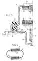
- FIG. 3 there is shown in axial half-section the purely mechanical part of a practical embodiment of the device of FIG. 2, FIG. 4 being a cross-section view of the spring made of tubular composite material, as well as of its means of connection to the motor 1 and to the member 5.
- FIG. 3 10 designates a structure integral with the engine and suitable for securing, by means of an axial stud 11 with internal thread, on the one hand between this engine and a rigid structure 12, comprising at its base the aforementioned rigid structure 4, and on the other hand between this same motor and the system 2 with relatively low stiffness.
- the relatively rigid stops have also been referenced 3; an example of their possible structure has been described above. These stops have a rigid frame 13 by which they can be secured to the body 14 of the vehicle.
- an elastic system 2 is used a tubular member with an elongated cross section and a horizontal axis, which member is advantageously made of a composite material (resin reinforced with resistant fibers), for the reasons indicated above.
- the means of connection of this tubular member 2 to the jack 5 preferably comprise holding plates such as 18, arranged on either side of the wall of the member 2, with the interposition of a layer 19 of elastic material, for example in elastomer.
- connection mode is provided on the motor side, the wall of the tubular member 2 being clamped between an inner plate 20 and the rigid structure 12, again with the interposition of a layer of elastomer or the like.
Landscapes
- Engineering & Computer Science (AREA)
- Mechanical Engineering (AREA)
- General Engineering & Computer Science (AREA)
- Chemical & Material Sciences (AREA)
- Combustion & Propulsion (AREA)
- Transportation (AREA)
- Health & Medical Sciences (AREA)
- Child & Adolescent Psychology (AREA)
- Arrangement Or Mounting Of Propulsion Units For Vehicles (AREA)
- Vibration Prevention Devices (AREA)
Applications Claiming Priority (2)
| Application Number | Priority Date | Filing Date | Title |
|---|---|---|---|
| FR8911389A FR2651290B1 (fr) | 1989-08-30 | 1989-08-30 | Dispositif de suspension elastique, en particulier pour moteur de vehicule. |
| FR8911389 | 1989-08-30 |
Publications (1)
| Publication Number | Publication Date |
|---|---|
| EP0415844A1 true EP0415844A1 (de) | 1991-03-06 |
Family
ID=9384998
Family Applications (1)
| Application Number | Title | Priority Date | Filing Date |
|---|---|---|---|
| EP90402380A Ceased EP0415844A1 (de) | 1989-08-30 | 1990-08-28 | Gerät für elastische Aufhängung insbesondere für einen Fahrzeugmotor |
Country Status (2)
| Country | Link |
|---|---|
| EP (1) | EP0415844A1 (de) |
| FR (1) | FR2651290B1 (de) |
Citations (3)
| Publication number | Priority date | Publication date | Assignee | Title |
|---|---|---|---|---|
| FR2465927A1 (fr) * | 1979-09-18 | 1981-03-27 | Nissan Motor | Systeme absorbant les vibrations, a utiliser dans un vehicule |
| EP0042068A2 (de) * | 1980-06-14 | 1981-12-23 | Messerschmitt-Bölkow-Blohm Gesellschaft mit beschränkter Haftung | Ovaler Federrahmen |
| EP0081085A1 (de) * | 1981-11-20 | 1983-06-15 | Nissan Motor Co., Ltd. | Auf Vibrationen reagierende Einbauvorrichtung für einen Fahrzeugmotor |
Family Cites Families (3)
| Publication number | Priority date | Publication date | Assignee | Title |
|---|---|---|---|---|
| JPS5241775A (en) * | 1975-09-30 | 1977-03-31 | Toyoda Gosei Co Ltd | Vibration damping elastic support |
| JPS56116519A (en) * | 1980-02-20 | 1981-09-12 | Nissan Motor Co Ltd | Engine mount of car |
| JPS5923139A (ja) * | 1982-07-30 | 1984-02-06 | Toyota Motor Corp | 振動吸収方法 |
-
1989
- 1989-08-30 FR FR8911389A patent/FR2651290B1/fr not_active Expired - Lifetime
-
1990
- 1990-08-28 EP EP90402380A patent/EP0415844A1/de not_active Ceased
Patent Citations (3)
| Publication number | Priority date | Publication date | Assignee | Title |
|---|---|---|---|---|
| FR2465927A1 (fr) * | 1979-09-18 | 1981-03-27 | Nissan Motor | Systeme absorbant les vibrations, a utiliser dans un vehicule |
| EP0042068A2 (de) * | 1980-06-14 | 1981-12-23 | Messerschmitt-Bölkow-Blohm Gesellschaft mit beschränkter Haftung | Ovaler Federrahmen |
| EP0081085A1 (de) * | 1981-11-20 | 1983-06-15 | Nissan Motor Co., Ltd. | Auf Vibrationen reagierende Einbauvorrichtung für einen Fahrzeugmotor |
Non-Patent Citations (3)
| Title |
|---|
| PATENT ABSTRACTS OF JAPAN vol. 1, no. 101 (M-77)(2903) 8 septembre 1977, & JP-A-52 41775 (TOYOTA GOSEI KK) 31 mars 1977, * |
| PATENT ABSTRACTS OF JAPAN vol. 5, no. 199 (M-102)(871) 17 décembre 1981, & JP-A-56 116519 (NISSAN JIDOSHA KK) 12 septembre 1981, * |
| PATENT ABSTRACTS OF JAPAN vol. 8, no. 116 (M-299)(1553) 30 mars 1984, & JP-A-59 23139 (TOYOTA JIDOSHA KK) 6 février 1984, * |
Also Published As
| Publication number | Publication date |
|---|---|
| FR2651290B1 (fr) | 1994-05-06 |
| FR2651290A1 (fr) | 1991-03-01 |
Similar Documents
| Publication | Publication Date | Title |
|---|---|---|
| FR2670552A1 (fr) | Attache hydroelastique de suspension et biellette de liaison geometrique liee a cette attache. | |
| CA2634967C (fr) | Suspension d'un turbomoteur a la structure d'un aeronef | |
| CA2044275C (fr) | Procede de suspension de roue de vehicule | |
| FR2492026A1 (fr) | Dispositif porteur en caoutchouc possedant une capacite d'amortissement pneumatique | |
| FR2474974A1 (fr) | Structure de montage de moteur pour vehicule automobile | |
| FR2974335A1 (fr) | Pantographe pour vehicule ferroviaire | |
| FR2711201A1 (fr) | Amortisseur à effet d'amortissement variable en fonction de la charge. | |
| EP0223712A1 (de) | Änderungen an hydraulischen Dämpfern | |
| FR2636391A1 (fr) | Perfectionnements apportes aux manchons antivibratoires hydrauliques | |
| FR2495718A1 (fr) | Support amortisseur, notamment pour moteur a combustion interne de vehicule automobile | |
| EP1043514B1 (de) | Drehmomentanlaufsdämpfungsvorrichtung | |
| FR2914716A1 (fr) | Butee de compression hydraulique, notamment pour amortisseur hydraulique de suspension de vehicule automobile | |
| FR2651290A1 (fr) | Dispositif de suspension elastique, en particulier pour moteur de vehicule. | |
| EP0108000A1 (de) | Anti-Kippvorrichtung für Antriebsaggregat eines Kraftfahrzeuges | |
| EP0148060A2 (de) | Aufhängung mit Niveau und Anschlagpufferregelung | |
| FR2713297A1 (fr) | Perfectionnements aux dispositifs antivibratoires hydrauliques. | |
| EP0498710B1 (de) | Elastisches Lager mit wechselnder Steifheit | |
| EP4040005A1 (de) | Schwingungsfreie halterung und fahrzeug mit einer solchen schwingungsfreien halterung | |
| EP1067309B1 (de) | Hydroelastisches Lager für die Antriebseinheit in einem Kraftfahrzeug | |
| FR2814785A1 (fr) | Biellette de suspension d'un groupe moto-propulseur de vehicule automobile et dispositif de suspension comportant une telle biellette | |
| EP2448818A1 (de) | System zur anbringung eines antriebsmotors | |
| EP0520881B1 (de) | Aufhängungsarm für eine schwingende Anlage, insbesondere für eine Fahrzeugbrennkraftmaschine | |
| EP1978277B1 (de) | Ausgleichsmodul für einen Fahrzeughydraulikdämpfer und Dämpfer, der mit einem solchen Ausgleichsmodul ausgestattet ist | |
| FR2829545A1 (fr) | Support antivibratoire et dispositif antivibratoire comportant un tel support | |
| FR2879274A1 (fr) | Butee acoustique pilotable et procede de controle de la rigidite de la butee |
Legal Events
| Date | Code | Title | Description |
|---|---|---|---|
| PUAI | Public reference made under article 153(3) epc to a published international application that has entered the european phase |
Free format text: ORIGINAL CODE: 0009012 |
|
| AK | Designated contracting states |
Kind code of ref document: A1 Designated state(s): BE DE ES GB IT LU NL SE |
|
| 17P | Request for examination filed |
Effective date: 19910601 |
|
| 17Q | First examination report despatched |
Effective date: 19920429 |
|
| STAA | Information on the status of an ep patent application or granted ep patent |
Free format text: STATUS: THE APPLICATION HAS BEEN REFUSED |
|
| 18R | Application refused |
Effective date: 19921017 |