EP0416105A1 - Filtre de lumiere a interference selective et dispositif optique l'utilisant - Google Patents
Filtre de lumiere a interference selective et dispositif optique l'utilisant Download PDFInfo
- Publication number
- EP0416105A1 EP0416105A1 EP89907364A EP89907364A EP0416105A1 EP 0416105 A1 EP0416105 A1 EP 0416105A1 EP 89907364 A EP89907364 A EP 89907364A EP 89907364 A EP89907364 A EP 89907364A EP 0416105 A1 EP0416105 A1 EP 0416105A1
- Authority
- EP
- European Patent Office
- Prior art keywords
- layer structure
- light filter
- radiation
- filter according
- interference light
- Prior art date
- Legal status (The legal status is an assumption and is not a legal conclusion. Google has not performed a legal analysis and makes no representation as to the accuracy of the status listed.)
- Withdrawn
Links
Images



Classifications
-
- G—PHYSICS
- G02—OPTICS
- G02B—OPTICAL ELEMENTS, SYSTEMS OR APPARATUS
- G02B5/00—Optical elements other than lenses
- G02B5/20—Filters
- G02B5/28—Interference filters
- G02B5/285—Interference filters comprising deposited thin solid films
- G02B5/287—Interference filters comprising deposited thin solid films comprising at least one layer of organic material
-
- G—PHYSICS
- G02—OPTICS
- G02B—OPTICAL ELEMENTS, SYSTEMS OR APPARATUS
- G02B5/00—Optical elements other than lenses
- G02B5/20—Filters
- G02B5/28—Interference filters
- G02B5/289—Rugate filters
Definitions
- the invention relates to optical devices, and more particularly relates to selective interference light filters and optical devices using the same.
- the invention can be used in spectroscopy, lighting technology, in optical and laser device construction, in carrying out space research.
- Interference light filters which contain two or more groups of alternating layers of insulating material with different refractive index, which have an optical thickness which is a quarter wavelength of a luminous flux directed onto a light filter (SU, A, 539284; SU, A, 881647).
- Such filters are complicated to manufacture, protective coatings are necessarily applied to them, which, by additionally complicating the process of manufacturing the light filters, also the optical properties of the light filter, i.e. the radiation permeability, deteriorate.
- the wavelength can be changed continuously within very narrow limits.
- Selective interference filters which have a layer structure, from each layer of which a light radiation directed onto the light filter is reflected.
- the layer structure is formed from a dielectric layer applied to a metal base, which has a half-width that can be divided by ⁇ of a phase, and an even number of alternating quarter-wave layers from two dielectrics with a high or low refractive index.
- This combination of layers is from above covered with a metal absorption layer that has a thickness much thinner than the working wavelength.
- Such known light filter reflects not only the selective wavelengths that go beyond the limits of the reflection band and represent interference.
- these light filters have disadvantages that are the same as those set out above.
- Optical devices namely spectral devices (IVPeisakhson “Optika spektralnykh priborov / Optik der spectraltechnik /", 1975, publisher “Mashinostroenie”, Leningrad, pp. 5 to 10), are known which have an entrance and an exit slit, a collimator and a chamber objective, a selective, for example a dispersing system, which is made on the basis of a dispersing primate or a diffraction grating, and contain a receiving device.
- spectral devices allow the working wavelength to be changed continuously, but the presence of a narrow entrance slit limits the light intensity of these devices with regard to the luminous flux, which is why only intensive radiation can be examined.
- Optical devices which contain a source of continuous radiation, one or two selecting elements, a holder or a cuvette for the object to be irradiated. These devices can include lenses and a radiation receiver. In these devices, either a prism or a diffraction grating or light filter serve as the selecting element (V.V. Leebedeva "Tekhnika opticheskoi spektoskopii /technik der Optik Spektoskopie /", 1977, Verlag der Moscow University, Moscow, p. 166).
- the application of the prism and the diffraction grating requires the introduction of a gap limiting the light intensity.
- the wavelengths are selected discretely, for which purpose sets of light filters that cannot be changed according to the wavelengths are used.
- the use of a wedge light filter that can be changed according to the wavelengths also necessitates the introduction of a slit that limits the light intensity.
- the wedge interference light filter is manufactured by wedge-shaped evaporation of layers of pure materials in a vacuum. This technology is very complicated, which is why the devices with the wedge filters are not widely used.
- the invention aims to create a selective narrow-band interference light filter which can be changed according to the wavelength, which has a simpler production technology and is multifunctional.
- the invention has for its object to provide a selective interference light filter and an optical device using the same, which allow to change the working wavelength when changing the angle of incidence of light radiation by changing the path difference of interference beams within wide limits.
- the object is achieved in that in the selective interference light filter, which has a layer structure, each layer of which is reflective for radiation directed onto the light filter, the layers of the layer structure are carried out equidistantly with a periodically changing refractive index according to the invention, and by irradiating an element arranged in front of a mirror only in the process of irradiation and made of a light-sensitive material that is transparent to the radiation with at least one monochromatic radiation of a predetermined wavelength are formed.
- the light filters according to the invention are distinguished by the possibility of a continuous change in the working wavelength within very wide limits.
- the layer structure reflects different wavelengths depending on the angle of incidence of light on this structure.
- the changeover range of the length of a wave retroreflected by a layer structure depends on an effective refractive index of this structure, and the larger the refractive index, the narrower the changeover range.
- the element to be irradiated can either be produced from a photo emulsion based on silver salts or from bichromated gelatin, or from photo-registering polymerizing agent, or from photopolymerizing composition.
- Vacuum evaporation generally produces a maximum of 30 to 40 layers.
- the further increase in the number of layers leads to the storage of defects, which is why it does not increase the reflection factor and does not narrow the spectral band.
- n 1 and n 2 are materials with a large difference in refractive indices n 1 and n 2. Since n 1 must not be below 1.3, n 2 is generally greater than 2. As a result, the effective refractive index of a layer system proves to be close to 2 or above.
- the method for producing the light filter according to the invention allows light filters with a large number of layers (from approximately 100 to 200) to be used automatically the accuracy to be observed of the resulting layer thicknesses (half wavelength).
- the effective refractive index of the layer system remains close to the refractive index of the light-sensitive raw material. (For a photo emulsion made of silver salts, it is approximately 1.5).
- the large number of layers ensures a high reflection factor and a narrow spectral band (not worse than in the case of filters produced by vapor deposition) with a low degree of modulation of the refractive index, while the low effective refractive index ensures a wide changeover range for the wavelength.
- the light filter prefferably has a substrate to which a layer structure is applied.
- the light filter which has a substrate on which a layer structure is applied, has the following advantages over a light filter without a substrate: high strength due to the strength of the substrate, higher reflection factor, narrower spectral band and better contrast because of the removal of a beam from the interference is reflected at the air - layer structure boundary.
- the substrate can serve to suppress interference maxima of higher orders compared to the first working order.
- At least one prism, on the reflection surface of which a layer structure can rest, while the light radiation can be directed onto any free prism surface, or at least one optical wedge, on the one surface of which a layer structure can be applied, while the light radiation on the other surface, can be used as the substrate can be directed, or serve a lens-shaped element.
- the light filter with a prism-shaped substrate extends the switching range for the working wavelengths.
- the light filter in which the optical wedge appears as a substrate has the advantage over a light filter with a flat substrate that the beam reflected at the air - substrate boundary is not only linearly separated from the interference beams, but also has a different direction, such as this is also the case with the prismatic substrate.
- the advantage of the light filter with the flat substrate is retained in the light filter with the wedge - it has smaller dimensions, while its entrance and exit surfaces coincide.
- the light filter with the lenticular substrate is not only a filtering, but also a focusing optical element.
- the layer structure can each have two or more combinations of equidistant layers, each of which is assigned to a separate wavelength of the monochromatic radiation.
- Such a light filter is polychrome. It reflects two or more wavelengths at the same time, each of which is switched to the light filter when the angle of incidence of the radiation changes.
- the combinations of the equidistant layers are arranged one behind the other in the layer structure in the beam path of the light radiation directed onto the layer structure and are spatially coincident.
- Such a light filter is manufactured much more easily than a similar known light filter.
- the spatial coincidence of the combinations of the equidistant layers makes it possible to obtain the ratio of the predetermined wavelengths with a high degree of accuracy during reflection, because the different combinations of the layers are simultaneously (at the same time) receive.
- two or more combinations of the equidistant layers to be formed by parallel bundles of the monochromatic radiation, the layer structure containing individual sections which represent combinations of the equidistant layers which correspond to individual sections of the wavefront of the light radiation directed onto the layer structure.
- Such a light filter delivers spatially separated beams of different wavelengths during reflection.
- the layer structure has layers whose aquidistance in the cross section of the layer structure is fulfilled by a plane which is simultaneously perpendicular to any layer and to the direction of the change in layer thickness, and is formed by radiation which is formed by a continuous spectrum is characterized.
- Such a light filter allows the wavelength to be changed not only by changing the angle of the incidence of light onto the light filter, but also by longitudinally displacing the light filter in the vicinity of a slit diaphragm.
- the present light filter is characterized by a very simple manufacturing technology.
- a device for compressing them can be arranged on the layer structure, which ensures a linear change in the thickness of the equidistant layers along the layer structure.
- the change in the refractive index is achieved with very simple means.
- the prism can have the shape of a rhomboid in the layer have, on the two symmetrical side surfaces the same layer structures are applied.
- the prism can also have two pairs of mutually symmetrical side surfaces with a common plane of symmetry, and the layer structures can rest on each side surface of a pair.
- Such a light filter is selective both according to the wavelength and the angle of incidence. It reflects the light radiation of only one wavelength, which propagates in a certain direction, and can also have smaller dimensions and mass due to the removal of non-functioning parts of the rhomboid.
- the light filter has a body, in the walls of which two openings are made for the radiation passage to the layer structure or for the exit of the filtered radiation are.
- the layer structure can be arranged in the body so as to be pivotable and / or linearly displaceable with respect to the guided radiation.
- the emitted filtered radiation is not limited by the opening in the body, which can be important in those constructions of the light filter where the filtered radiation shifts in space.
- the light filter can also have a body, one wall of which the entry surface of the prism or the optical wedge will serve, while an aperture for the beam passage to the layer structure can be attached to the opposite body wall, the layer structure and the aperture with the possibility of mutual pivoting and / or a linear displacement can be carried out.
- the beam direction and / or the length of the reflected wave can be scanned in such light filters.
- the present selective interference light filter is used as an selecting element in an optical device which contains a selecting element for separating one or more wavelengths from radiation incident thereon is pivotally arranged.
- This device has a greater light intensity than the known ones.
- the light filter according to the invention ensures a continuous change in the working wavelength, has a narrow spectral band, a high contrast and reflection factor.
- FIG. 5 shows a light filter according to the invention with several prisms
- FIG. 6 shows a light filter according to the invention with several ioptical wedges
- FIG. 7 shows a light filter according to the invention with combinations of layers arranged one behind the other in the beam path;
- FIG. 8 shows a light filter according to the invention with spatially separated combinations of the layers
- FIG. 10 shows a light filter according to the invention with a stepless change in the wavelength of a filtered radiation
- FIG. 11 shows a light filter according to the invention with a device for compressing a layer structure
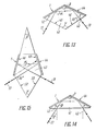
- FIG. 13 shows a light filter according to the invention with a substrate having the shape of a rhomboid in section
- FIG. 14 shows a light filter according to the invention with a substrate having the shape of an isosceles triangle in section;
- FIG. 16 shows a light filter according to the invention with a body
- FIG. 17 shows a further embodiment of the light filter according to the invention with a body
- FIG. 18 shows a basic circuit diagram of an optical device according to the invention.
- the selective interference light filter has a layer structure 1 (FIG. 1) which contains equidistant layers 2, 3, 4 and 5 with a refractive index that changes periodically according to the depth. 1 schematically indicates how such a filter is manufactured.
- An element made of a transparent, light-sensitive material is taken, irradiated with a parallel luminous flux 6 by an optical system 7 from a light source 8.
- the element to be irradiated is arranged in front of a metal mirror 9, which is removed after the irradiation.
- the irradiation is carried out with at least one monochromatic radiation of a predetermined wavelength
- the wave of light flux 6 reflected by mirror 9 interferes with a striking wave, creating standing waves.
- the refractive index of the light-sensitive material changes differently.
- the element made of the light-sensitive material is given a layer structure 1.
- the wave bellies 10 correspond in that they come to lie equidistantly at a distance of ⁇ 0 / 2n from one another in the element to be irradiated, where n is the refractive index of the material the layer structure 1 the equidistant layers 2 to 5, which is why the periodicity of the layers 2 to 5 and consequently the layer thickness is.
- Levels 12 of maximum change in the refractive index of the light-sensitive material are indicated schematically by vertical lines.
- the number N of layers 2 to 5 in layer structure 1 depends on the thickness D of the element to be irradiated and the thickness d of each layer 2 to 5 and is determined by the relationship given.
- Each layer 2 to 5 is partially reflective for light radiation directed onto the layer structure.
- the interference of the beams reflected by the layers 2 to 5 has a maximum for a certain wavelength, which is the same as the path difference of the interference waves.
- the radiation of this wavelength is filtered off by the light filter under consideration.
- the element to be irradiated is made of a transparent, light-sensitive material, as which either a photo emulsion based on silver salts or bichromated gelatin, or photo-registering polymerizing agent, or a photopolymerizing composition is used.
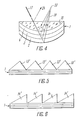
- the layer structure 1 has a substrate, which is either a prism 13 (FIG. 2) or an optical one Wedge 14 (Fig. 3) is used, or the substrate is in the form of a lens I5 (Fig. 4).
- the layer structure 1 is applied to a reflecting surface 16, while the light radiation 17 is directed onto any free surface 18.
- the filtered radiation 19 emerges through another surface 20 of the prism 13.
- the layer structure 1 is applied to a surface 21 (FIG. 3) of the optical wedge 14, the light radiation 17 is directed onto its surface 22, and the filtered radiation 19 emerges through the same surface 22.
- the light filter When using the lens 15 (FIG. 4), the light filter has a construction similar to that described above and focuses the radiation 17 next to its filtering point and in the focal point 23 of the lens 15 if the light radiation 17 was collimated.
- the radiation 24 (FIGS. 2 to 4) reflected at the boundary between the surrounding medium and the light filter has a direction deviating from the filtered radiation 19 in all the embodiments considered.
- the substrate may contain more than one prism 13 or wedge 14 as shown in FIGS. 5 and 6.
- the prisms 13 '(or wedges 14') lie along the structure 1, and their number depends on the length of the structure 1.
- Each of the prisms 13 ' has dimensions and consequently a mass which are much smaller than in the embodiment according to FIG. 2 when a prism 13 is used.
- the mass and dimensions of all prisms 13 ' are smaller than the mass and dimensions of prism 13.
- the overall dimensions and the mass of the entire light filter according to FIG. 5 are therefore considerably smaller than in the embodiment according to FIG. 2, and it can be said that the construction of the entire light filter is quasi-flat.
- the design of the light filter is similar even when using a large number of wedges 14 '(Fig. 6).
- the element to be irradiated can be subjected to the action of two or more radiations with different wavelengths. Combinations of equidistant layers assigned to these wavelengths are formed in the element. The combinations of the layers in the layer structure are arranged in different ways, which are determined by the tasks and determination of the finished light filter,
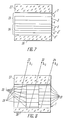
- the combinations 25 and 26 of the layers 2 to 5 and 2 ', 3', 4 ', 5' lie one behind the other in the beam path of the radiation 17 (FIG. 2).
- the light filter has two substrates 27 (FIG. 7) and 28 made of glass.
- the combinations 29, 30 and 31 are spatially separated along the layer structure 1, which has individual sections, which is why the radiations 32, 33, 34 of the respective wavelengths ⁇ 1, ⁇ 2, ⁇ 3, which are filtered by all combinations 29 to 31, result as a result the radiation effect appeared on each section of structure 1, are separated in space.
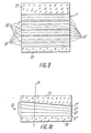
- a light filter is schematically arranged, for the manufacture of which an element has been irradiated by radiation with a continuous spectrum.
- the layers 2 ′′, 3 ′′, 4 ′′, 5 ′′ lie in a layer structure 35 equidistant in a cross section through one of the layers 2 ′′ to 5 ′′ and the direction of a change in the thickness of the layers 2 "" to 5 "vertical plane 36.
- the thickness of the layers 2" to 5 “changes monotonically along the layer structure 35.
- Such a light filter allows a spectrum of radiation to be examined to be obtained or a stepless changeover of the Wavelength of the filtered radiation 17 (Fig. 1) by moving it in front of any aperture in a slit form (not shown in the drawing).
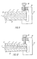
- a light filter has similar functional capabilities, in which a device 37 for compressing the same is arranged on the layer structure 1 (FIG. 11). It contains a screw clamp 38 and a screw 39 which changes the pressure force of the screw clamp 38.
- the layer structure 1 is made of an elastic compressible material, for example of bichromated gelatin.
- the layers 2 ′′ to 5 ′′ have an equidistance (FIG. 12) only in a cross section in analogy to this, as is shown in FIG. 10.
- the prism according to the invention can have an average shape of a rhomboid 40 (FIG. 13) or an isosceles triangle 41 (FIG. 14), which represents a special embodiment of the rhomboid and its properties are therefore not considered separately.
- Two layer structures 1 and 44 are applied to two symmetrical side surfaces 42 (FIG. 13), 43 of the rhomboid 40.
- the light radiation 17 is directed onto a free surface 45, while the filtered radiation 19, by being successively reflected by the layer structures 1 and 44, emerges through the other free surface 46.
- the angle ⁇ between the free surfaces 45 and 46 is based on the following relationships: selected, where ⁇ is the angle between the surfaces 42 and 43, on which the layer structures 1 and 44 are applied.
- prism 47 (FIG. 15) has a complicated shape with at least two pairs of side surfaces symmetrical in pairs 48, 49 or 50, 51 with a common plane of symmetry on: for a pair of surfaces 48, 49, layer structures 1, 4 are plotted, while the angles ⁇ and ⁇ between surfaces 48, 49 and 50, 51 of the pairs according to Relationship (3) can be selected.
- the light radiation 17 strikes the free surface 50 and is sequentially reflected by the structures 44 and 1, while the filtered radiation 19 emerges through the free surface 15.
- the light filter containing the layer structure 1 on the prism 13 has a body 52 in which an entry opening 53 for the passage of the radiation 17 and an opening 54 for the exit of the filtered radiation 19 are made.
- the inlet opening 53 forms a diaphragm, as which any light guide can appear, for example.
- the layer structure 1 is pivotable with respect to the radiation 17 supplied about the body 52 with the possibility of a simultaneous or separate longitudinal displacement.
- the prism 13 with the layer structure has a rotating mechanism which contains, for example, a worm drive 57, 58 and a handle 59.
- the prism 13 is attached to the gear 57 of the worm gear 57, 58.
- the prism is linearly displaced by means of a screw 60, which interacts with the toothed wheel 57, which is sprung by a spring 61.
- the radiation 17 is transmitted to the prism through a diaphragm formed by the openings 53, 55, 56 and, after being filtered off, emerges through the opening 54 on the opposite wall of the body 52.
- the body 52 ' (FIG. 17) can be arranged outside the light filter, and one wall thereof serves as the entry surface 16 of the prism 13.
- a diaphragm is arranged on the opposite wall 62 of the body 52', which is formed by a system of openings 53, 55 and 56 is formed in a sleeve 63.
- the longitudinal displacement device of the prism 13 contains a screw 64 and a spring 65 which cooperate with the sleeve 63 of the diaphragm and enable a mutual longitudinal displacement of the diaphragm and the prism 13 by changing the angle of incidence of the radiation 17 on the layer structure 1.
- the pivoting of the prism 13 fastened on a rotary bearing 66 is achieved by changing the shape of the body 52 ', as a corrugated tube is used.
- the filtered radiation 19 leaves the light filter through the surface 20.
- an optical device (FIG. 18) which contains the present light filter as a selecting element.
- the optical device contains a collimator lens 66, the mount 67 of which serves as an entry opening, a light filter 68 and a radiation receiver 69.
- the optical device of the given construction represents a gapless, bright monochromator.
- a radiation source 70 is introduced into the optical device, which is characterized by a continuous spectrum.
- the device serves as a monochromatic reflector with an adjustable wavelength.
- the selective interference light filter works as follows.
- Light radiation 17 is directed onto the light filter, and each layer 2 to 5 (FIG. 2) of the layer structure 1 reflects a small part of this radiation.
- a reflected radiation 19 is formed which contains many light beams which have a constant path difference from one another which depends on the layer thickness d, the refractive index n and the angle ⁇ of the incidence of light on the layer structure 1. The result of the interference amounts to the fact that the interference maximum is only reached for the wavelength ⁇ that the condition enough.
- the light-sensitive material of the element to be irradiated is chosen to be practically transparent for the target wavelength ⁇ o , which at the same time changes its refractive index slightly under the effect of light and has sufficient resolution for the formation of a layer structure (the internal inhomogeneities in the material should be less than ⁇ / 15) .
- the radiation 21 reflected at the air-light filter boundary is linearly separated from the radiation 19 reflected by the layers 2 to 5 or even propagates in another direction. Therefore, it does not interfere with the radiation 19 and does not distort the interference image.
- the separation of the radiation 24 reflected at the air / light filter boundary is angular, and the changeover range for the wavelength is wider than in the case of a plane-parallel substrate.
- the lens 15 (FIG. 4) in the reflected radiation 19, the maximum is observed for one wavelength, the monochromatic light being focused at the focal point 23 of the lens 15 when the filter is incident on a plane-parallel light beam.
- the light filter with the combinations 25 and 26, 29, 30 and 31 reflects two or more wavelengths upon the incidence of the radiation 17 characterized by a continuous spectrum, whereby the waves in the room can be covered or separated (29 ', 30' and 31 'or 29, 30, 31).
- the wavelength ⁇ of the reflected light changes.
- the possibility of changing the wavelength of the reflection light by changing the angle of light incidence on the filter is retained.
- the construction of the light filter shown in Figs. 11, 12 enables the value d ⁇ / dx, i.e. to change the dispersion of the light filter.
- the light filter according to FIGS. 13, 14 reflects only one wavelength and only in the case when the wave of this length falls on the light filter at a certain angle (The parameters of the prism are chosen such that radiation incident on the light filter normal to the entrance surface 31 is separated).
- the light filter which is designed in the manner as shown in FIGS. 15, 16, 17, only separates a light that is normally incident thereon, because, for example, the diaphragm (FIGS. 16, 17) does not transmit rays that are incident at an oblique angle, and with a certain mutual orientation of the diaphragm and the layer structure 1, the light filter filters out the light of only one wavelength.
- the light filter is set to any wavelength from a desired range.
- an angular scan is carried out, i.e. the direction of the light source is determined with a desired wavelength (not shown in the drawings).
- the optical device which contains the light filter under consideration as a selecting element, a collimator element and a radiation receiver, can also be used as gapless bright monochromator work, with the help of which the spectrum of any, including weak, radiation sources is analyzed.
- the light from the source strikes the lens, while the light filter 1 reflects the selected wavelength and directs it to the radiation receiver. By swiveling the light filter, the wavelength is changed.
- the device is used to irradiate various objects.
- the light from the source with the continuous spectrum is incident on the collimator lens and is filtered by the light filter.
- a monochromatic radiation is generated at the exit which irradiates the object.
- the selective interference light filter has a layer structure which is produced from a photo emulsion which contains a silver bromide.
- the thickness of the layer structure is 18 ⁇ m. This contains at least 85 layers.
- the refractive index varies from 1.52 to 1.60.
- the filtered radiation has the wavelength ⁇ in a range from 480 to 633 nm.
- the reflection factor amounts to up to 40% in the green spectral range.
- the spectral bandwidth makes up 8 to 10 nm in the entire changeover range for the wavelength.
- the selective interference light filter contains a layer structure made of brominated gelatin (with ammonium dichromate) is made.
- the thickness of the layer structure is 10 ⁇ m. This contains at least 60 layers.
- the refractive index varies from 1.50 to 1.60.
- the filtered radiation has the wavelength ⁇ in a range from 380 to 488 nm.
- the reflection factor is up to 70% in the blue-green spectral range.
- the spectral bandwidth is between 5 and 6 nm.
- the selective interference light filter contains a layer structure made of photo-registering polymerizing agent of the type of a registering oxidant with anthracene.
- the thickness of the layer structure is 1 nm. This contains at least 4500 layers.
- the filtered radiation has the wavelength ⁇ in a range from 475 to 633 nm.
- the reflection factor is up to 10% in the green spectral range.
- the spectral bandwidth is 0.1 to 0.2 nm.
- the selective interference light region contains a layer structure which is produced from a liquid polymerizing composition.
- the composition has a radically polymerizing vinyl monomer and a stabilizing agent.
- the thickness of the layer structure is 20 ⁇ m.
- the filtered radiation has a wavelength of 350 to 442 nm.
- the reflection factor is 15%, the spectral bandwidth 3 to 4 nm.
- the selective interference light filter contains a layer structure made of a silver bromide Photo emulsion is made.
- the thickness of the layer structure is 21 ⁇ m. This contains at least 100 layers.
- the layer structure lies on the hypotenuse surface of a three-sided prism, which has angles of 90 °, 45 °, 45 °.
- the filtered radiation has a wavelength in a range from 360 to 610 nm.
- the reflection range is from 40% in the red and violet spectral range to 70% in the green spectral range.
- the spectral bandwidth is 8 to 10 nm.
- the selective interference light filter contains a layer structure which is produced from a photo emulsion comprising silver bromide.
- the thickness of the layer structure is 21 ⁇ m. This contains at least 100 layers.
- the layer structure is applied to a surface of an optical wedge at an angle of 30 °.
- the filtered radiation has a wavelength in a range from 570 to 633 nm.
- the reflection factor is about 60%.
- the selective interference light filter contains a layer structure which is produced from a photo emulsion comprising silver bromide.
- the thickness of the layer structure is 21 ⁇ m.
- the layer structure is applied to a flat substrate.
- the filtered radiation has two wavelengths, which are in a bundle side by side reproduce. If a screen is set up in the radiation path of the filtered radiation, the spot on the screen consists of two parts of different colors. When the angle of incidence of the light radiation on the filter is changed from 0 to 35 °, the two lengths change, the shorter one changing from 380 to 488 nm and the longer one from 570 to 633 nm.
- the selective interference light filter contains a layer structure which is produced from a photo emulsion comprising silver bromide.
- the thickness of the layer structure is 42 ⁇ m.
- the layers produced by the first laser take up half the thickness of the plate, the other half thickness is occupied by the layers produced by the second laser.
- the first combination of the layers lies first in the radiation path of the radiation incident on the filter. Analysis of the filtered radiation shows that it contains two wavelengths at the same angle of incidence on the filter. When the angle of incidence changes, the wavelengths of the filtered radiation change from 570 to 633 and from 350 to 488 nm for ⁇ ' O or ⁇ " O .
- the selective interference light filter contains a layer structure which is produced from a photo emulsion comprising silver bromide.
- the filter is irradiated by a source characterized by a continuous spectrum, it becomes a radiation with a wavelength of 449 nm and with a spectral bandwidth of 10 nm, but only with a normal one Incidence of radiation filtered on the filter.
- the angle of incidence changes by 1 °
- the intensity of the filtered radiation drops twice, while when the angle of incidence changes by 2 °, the filter practically does not let light radiation through.
- the light filter according to the invention is selective, narrow-band, switchable according to the wavelength. It can be easier to manufacture and multifunctional to use.
- the switchable light filter which has a switchover range of 240 nm with a spectral bandwidth of 8 nm, can replace 30 switchable light filters with the same spectral band. Considering the cost of a light filter, the application of the invention has a noticeable economic effect.
- the invention can be used in spectroscopy, lighting technology, in optical and laser device construction, in carrying out space research.
Landscapes
- Physics & Mathematics (AREA)
- General Physics & Mathematics (AREA)
- Optics & Photonics (AREA)
- Exposure And Positioning Against Photoresist Photosensitive Materials (AREA)
- Optical Filters (AREA)
- Optical Modulation, Optical Deflection, Nonlinear Optics, Optical Demodulation, Optical Logic Elements (AREA)
Abstract
Applications Claiming Priority (1)
| Application Number | Priority Date | Filing Date | Title |
|---|---|---|---|
| PCT/SU1989/000032 WO1990008967A1 (fr) | 1989-02-03 | 1989-02-03 | Filtre de lumiere a interference selective et dispositif optique l'utilisant |
Publications (2)
| Publication Number | Publication Date |
|---|---|
| EP0416105A1 true EP0416105A1 (fr) | 1991-03-13 |
| EP0416105A4 EP0416105A4 (en) | 1992-04-08 |
Family
ID=21617400
Family Applications (1)
| Application Number | Title | Priority Date | Filing Date |
|---|---|---|---|
| EP19890907364 Withdrawn EP0416105A4 (en) | 1989-02-03 | 1989-02-03 | Selective interference light filter and optical device using it |
Country Status (3)
| Country | Link |
|---|---|
| EP (1) | EP0416105A4 (fr) |
| JP (1) | JPH03504771A (fr) |
| WO (1) | WO1990008967A1 (fr) |
Cited By (3)
| Publication number | Priority date | Publication date | Assignee | Title |
|---|---|---|---|---|
| EP0562827A1 (fr) * | 1992-03-25 | 1993-09-29 | Hughes Aircraft Company | Etalons comportant de couches dispersives |
| WO2001042821A1 (fr) * | 1999-12-09 | 2001-06-14 | Femtolasers Produktions Gmbh | Miroir a plusieurs couches |
| WO2002068999A3 (fr) * | 2001-02-26 | 2003-04-03 | Femtolasers Produktions Gmbh | Miroir de dispersion multicouche |
Families Citing this family (2)
| Publication number | Priority date | Publication date | Assignee | Title |
|---|---|---|---|---|
| BR9912618A (pt) * | 1998-07-31 | 2001-05-02 | Minnesota Mining & Mfg | Artigo compreendendo uma pelìcula óptica de múltiplas camadas e processo de fabricar o mesmo |
| DE102014014980A1 (de) * | 2014-10-07 | 2016-04-07 | Technische Universität Dresden | Richtungsselektiver interferometrischer optischer Filter |
Family Cites Families (12)
| Publication number | Priority date | Publication date | Assignee | Title |
|---|---|---|---|---|
| SE350616B (fr) * | 1971-03-02 | 1972-10-30 | Lkb Produkter Ab | |
| SU382041A1 (ru) * | 1971-09-24 | 1973-05-22 | Интерференционный фильтр | |
| SU611166A1 (ru) * | 1976-12-20 | 1978-06-15 | Предприятие П/Я Р-6303 | Устройство дл юстировани оптических элементов |
| SU862097A1 (ru) * | 1980-01-04 | 1981-09-07 | Предприятие П/Я А-1705 | Оптический переменный светоделитель |
| GB2071866B (en) * | 1980-03-13 | 1983-11-16 | Marconi Co Ltd | Colour selective holographic reflector |
| US4412719A (en) * | 1981-04-10 | 1983-11-01 | Environmental Research Institute Of Michigan | Method and article having predetermined net reflectance characteristics |
| US4420217A (en) * | 1982-12-16 | 1983-12-13 | The United States Of America As Represented By The Secretary Of The Army | Switchable on-axis optical bandstop filter |
| US4714309A (en) * | 1984-06-09 | 1987-12-22 | Pilkington P.E. Limited | Reflection holograms |
| SU1254398A1 (ru) * | 1985-01-07 | 1986-08-30 | Ленинградский Ордена Ленина И Ордена Трудового Красного Знамени Государственный Университет Им.А.А.Жданова | Широкополосное зеркало |
| IL79391A (en) * | 1985-08-14 | 1994-06-24 | Hughes Aircraft Co | Non-spherical patch with a stepped key and a display system that uses it |
| GB2207253B (en) * | 1986-11-11 | 1990-01-24 | Sec Dep For Trade & Industry T | Improvements in or relating to monochromators |
| US4957371A (en) * | 1987-12-11 | 1990-09-18 | Santa Barbara Research Center | Wedge-filter spectrometer |
-
1989
- 1989-02-03 WO PCT/SU1989/000032 patent/WO1990008967A1/fr not_active Ceased
- 1989-02-03 EP EP19890907364 patent/EP0416105A4/de not_active Withdrawn
- 1989-02-03 JP JP1506764A patent/JPH03504771A/ja active Pending
Cited By (5)
| Publication number | Priority date | Publication date | Assignee | Title |
|---|---|---|---|---|
| EP0562827A1 (fr) * | 1992-03-25 | 1993-09-29 | Hughes Aircraft Company | Etalons comportant de couches dispersives |
| WO2001042821A1 (fr) * | 1999-12-09 | 2001-06-14 | Femtolasers Produktions Gmbh | Miroir a plusieurs couches |
| US6873464B1 (en) | 1999-12-09 | 2005-03-29 | Femtolasers Produktions Gmbh | Multilayer mirror |
| WO2002068999A3 (fr) * | 2001-02-26 | 2003-04-03 | Femtolasers Produktions Gmbh | Miroir de dispersion multicouche |
| AT410721B (de) * | 2001-02-26 | 2003-07-25 | Femtolasers Produktions Gmbh | Dispersiver mehrschicht-spiegel |
Also Published As
| Publication number | Publication date |
|---|---|
| WO1990008967A1 (fr) | 1990-08-09 |
| EP0416105A4 (en) | 1992-04-08 |
| JPH03504771A (ja) | 1991-10-17 |
Similar Documents
| Publication | Publication Date | Title |
|---|---|---|
| DE60023524T2 (de) | Verbesserter polarisierender breitband drahtgitter-strahlteiler für den sichtbaren spektralbereich | |
| DE3913228C2 (de) | Spektroskopiesystem diffuser Reflexion und Verfahren zum Erhalten eines diffusen Reflexionsspektrums | |
| DE60130227T2 (de) | Optische vorrichtung mit einer wellenlängenabstimmbaren dispersionseinrichtung, die ein dispersionsvolumenbeugungsgitter verwendet | |
| DE102007063274B4 (de) | Mikroskop | |
| DE69028145T2 (de) | Verfahren und Vorrichtung zur Herstellung von Reflexionshologrammen | |
| DE69518244T2 (de) | Gerät zur durchführung einer spektralanalyse einer optischen lichtquelle mittels bildaufnahme und trennung bestimmter spektraler ordnungen | |
| EP0144950A2 (fr) | Objectif comportant des surfaces quadratiques pour la formation d'images de microzones | |
| DE2539183C2 (de) | Optisches Meßinstrument | |
| DE2857061C2 (de) | Linsensystem zur Strahlungskonzentration | |
| EP0212438A2 (fr) | Réseau de diffraction à réflexion ayant un haut coefficient de réflexion | |
| DE102004020250A1 (de) | Vorrichtung und Verfahren zur optischen Strahlhomogenisierung | |
| DE69631860T2 (de) | Optische Polarisationsvorrichtung und Flüssigkristall-Projektionssystem damit | |
| DE19627568A1 (de) | Anordnung und Verfahren zur konfokalen Mikroskopie | |
| DE1598089B2 (de) | Vorrichtung zur optischen Spektralanalyse | |
| EP1130439B1 (fr) | Méthode et dispositif d'illumination d'un objet transparent | |
| DE10215162B4 (de) | Strahlteilervorrichtung und Laserrastermikroskop | |
| EP0416105A1 (fr) | Filtre de lumiere a interference selective et dispositif optique l'utilisant | |
| DE2055026A1 (de) | Monochromator | |
| DE102020108117B4 (de) | Mikroskop und Verfahren zum Betreiben eines Mikroskops | |
| DE69711037T2 (de) | Verfahren zur korrektion von fehlern in einer linse | |
| DE69115460T2 (de) | Hochleistungs-absorptionsdetektor mit blitzlampe und kompaktem gefaltetem optischem system | |
| DE2435904A1 (de) | Vorrichtung zur erzeugung eines mehrfarbigen strahls sowie verfahren zum erzeugen eines solchen strahls | |
| DE3751148T2 (de) | Vorrichtung zur relativen erhöhung der tiefenschärfe und verbesserung des auflösungsvermögens bei vergrössernden systemen, insbesondere für mikroskope. | |
| DD302014A9 (de) | Selektives Interferenzlichtfilter und optisches Geraet unter Benutzung desselben | |
| DE2320937B2 (de) | Optische Vorrichtung zum Aufnehmen der Lichtabsorption in einem Objekt, das außerdem einen veränderlichen Brechungskoeffizienten aufweist |
Legal Events
| Date | Code | Title | Description |
|---|---|---|---|
| PUAI | Public reference made under article 153(3) epc to a published international application that has entered the european phase |
Free format text: ORIGINAL CODE: 0009012 |
|
| AK | Designated contracting states |
Kind code of ref document: A1 Designated state(s): AT DE FR GB IT NL SE |
|
| 17P | Request for examination filed |
Effective date: 19910118 |
|
| A4 | Supplementary search report drawn up and despatched |
Effective date: 19920220 |
|
| AK | Designated contracting states |
Kind code of ref document: A4 Designated state(s): AT DE FR GB IT NL SE |
|
| 17Q | First examination report despatched |
Effective date: 19931005 |
|
| STAA | Information on the status of an ep patent application or granted ep patent |
Free format text: STATUS: THE APPLICATION IS DEEMED TO BE WITHDRAWN |
|
| 18D | Application deemed to be withdrawn |
Effective date: 19940216 |