EP0416186A2 - Rotorschaufeln eines Axialverdichters besonders gebildet zur Behaltung der Existenz der mit Esp. angedeuteter Energie innerhalb ihren axialen Arbeitslänge bestimmt mit der Dimension L (I.3) - Google Patents
Rotorschaufeln eines Axialverdichters besonders gebildet zur Behaltung der Existenz der mit Esp. angedeuteter Energie innerhalb ihren axialen Arbeitslänge bestimmt mit der Dimension L (I.3) Download PDFInfo
- Publication number
- EP0416186A2 EP0416186A2 EP89312535A EP89312535A EP0416186A2 EP 0416186 A2 EP0416186 A2 EP 0416186A2 EP 89312535 A EP89312535 A EP 89312535A EP 89312535 A EP89312535 A EP 89312535A EP 0416186 A2 EP0416186 A2 EP 0416186A2
- Authority
- EP
- European Patent Office
- Prior art keywords
- ref
- plane
- vcm1
- esp
- blade
- Prior art date
- Legal status (The legal status is an assumption and is not a legal conclusion. Google has not performed a legal analysis and makes no representation as to the accuracy of the status listed.)
- Withdrawn
Links
- 230000008859 change Effects 0.000 claims description 8
- 230000006835 compression Effects 0.000 claims description 5
- 238000007906 compression Methods 0.000 claims description 5
- 230000003247 decreasing effect Effects 0.000 claims description 4
- 238000004519 manufacturing process Methods 0.000 claims description 2
- 230000003068 static effect Effects 0.000 abstract description 4
- 238000000034 method Methods 0.000 description 8
- 239000007787 solid Substances 0.000 description 7
- 239000000463 material Substances 0.000 description 6
- 230000004323 axial length Effects 0.000 description 5
- 101100306017 Caenorhabditis elegans rpb-2 gene Proteins 0.000 description 2
- 101150085800 RPA2 gene Proteins 0.000 description 2
- 230000009471 action Effects 0.000 description 2
- 238000004364 calculation method Methods 0.000 description 2
- 230000000694 effects Effects 0.000 description 2
- 230000003211 malignant effect Effects 0.000 description 2
- 101150060610 polr1b gene Proteins 0.000 description 2
- 230000002829 reductive effect Effects 0.000 description 2
- 230000000717 retained effect Effects 0.000 description 2
- 101150041101 Polr1a gene Proteins 0.000 description 1
- 101100351310 Rattus norvegicus Pdgfa gene Proteins 0.000 description 1
- 230000001133 acceleration Effects 0.000 description 1
- 230000008901 benefit Effects 0.000 description 1
- 238000002485 combustion reaction Methods 0.000 description 1
- 230000007850 degeneration Effects 0.000 description 1
- 230000001419 dependent effect Effects 0.000 description 1
- 238000009795 derivation Methods 0.000 description 1
- 230000018109 developmental process Effects 0.000 description 1
- 238000009792 diffusion process Methods 0.000 description 1
- 230000005484 gravity Effects 0.000 description 1
- 230000002427 irreversible effect Effects 0.000 description 1
- 230000007246 mechanism Effects 0.000 description 1
- 230000004048 modification Effects 0.000 description 1
- 238000012986 modification Methods 0.000 description 1
- 238000011144 upstream manufacturing Methods 0.000 description 1
Images






Classifications
-
- F—MECHANICAL ENGINEERING; LIGHTING; HEATING; WEAPONS; BLASTING
- F04—POSITIVE - DISPLACEMENT MACHINES FOR LIQUIDS; PUMPS FOR LIQUIDS OR ELASTIC FLUIDS
- F04D—NON-POSITIVE-DISPLACEMENT PUMPS
- F04D29/00—Details, component parts, or accessories
- F04D29/26—Rotors specially for elastic fluids
- F04D29/32—Rotors specially for elastic fluids for axial flow pumps
- F04D29/321—Rotors specially for elastic fluids for axial flow pumps for axial flow compressors
Definitions
- Multi stage axial flow compressors are used to effect the compression of large air mass flows to high pressures.
- Each individual stage comprising of a ring of rotor blades followed with running clearance between by a ring of stator blades.
- the rotor blade ring is required to add kinetic energy alone or kinetic and heat energy to the air while the stator ring of blades change the surplus whirl velocity kinetic energy into heat energy.
- the blade shape and speed of rotation being arranged also to maintain a constant value axial air velocity along all streamlines but not necessarily all of the same value.
- a specific embodiment of the invention is thus rotor blade rings, each blade of which has a precisely calculated shape such that the energy Esp-(1.2). generated in the air through the first portion of the blade ring is constructively used to help drive the second portion thus eliminating itself from the air flow.
- the Bernoulli type equation which identifies the various forms of energy involved in the action between the inlet plane (Plane 1.) and the plane which terminates the working length of the blade (Plane 3.) is qiven below:-
- W(1.3). The energy per unit air mass flow required to drive the Plane 1. to 3. portion of the rotor blade ring.
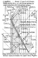
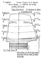
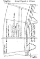
- the inlet and outlet plane outer edges are both equal in radius and angular extent. That at the outlet plane due to the air whirl velocity being angularly ahead in the direction as of the rotation of the blades, of the inlet plane.
- the inside edges are both arcs, that of the outlet plane being angularly ahead for the same reason as the outer arc. Both arcs are equal in angular extent but the arc at the outlet plane is at a larger radius than that at the inlet plane.
- the inside arcs can be at an equal, greater, or lesser axial distance apart than the outer arcs.
- the axial projection of both end planes are sectors of their respective annulus.
- the outer boundary surface that joins the two above planes together is of constant arc radius but not of angular extent, the latter being of minimum extent at Plane 2.
- the surface also spiralling at a varying rate from inlet to outlet plane.
- the inner boundary surface joining the two inner arcs is of a constant arc radius from Plane 1. to Plane 2., (optionally to Plane 3.). Plane 2. being position of minimum angular extent. From Plane 2. to Plane 4. (Outlet plane) both angular extent and arc radius increase at rates which are related to each other to maintain from Plane 2. a constant cross sectional area airstream to the outlet plane. Additional to the foregoing and similarly to the outer surface it spirals in the same direction.
- the airstream is divided by intermediate streamlines into lasser portions of the full air mass flow.
- the radial depth on Plane 1. is divided into an even number of equal portions.
- the air mass flowing between the common outer boundary and any one of the others is calculated for Plane 1. and is retained by the streamline to the outlet plane.
- Ep(1.2). ((v1./v2.) (y-1.) .- 1.).T1.C./(y-1.).
- vr2. Specific Volume of the air mass in the rear portion of the cylinder (Adjacent to piston).
- V1R. has the minimum velocity
- vb1 R . should have a value not exceeding (V1 R . + va1 R .).
- the rotor blade shape (As manufactured) when stationary is also its absolute shape.
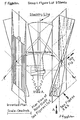
- V1. the rotor blade absolute shape continuously in contact with its relative shape on Plane 1. appears to move in an anti-clockwise direction like a pointer of a clock until at the designed speed it reaches the designed speed position.
- the absolute shape passes through a third position where it is disposed axially. This is the position where surge conditions would arise if the relative blade shapes did not give full static coverage to the inlet plane.
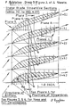
- the rotor blade at all radii should have a minimum arc length of one blade pitch.. (See Figure 9/9.)
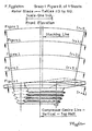
- the absolute lamina blade circular arc dimensions are measured from an axial line which passes through the blade point at Plane 1. and the axial length dimensions from Plane 1. along the line. Note also that all streamlines in the Synopsis are at a constant radius thus r(1.3).
- Front profile dimension designations are prefixed by the letters Fp and rear profile dimensions Rp.
- the mean centre line of air mass flow moved circumferentially one half blade pitch so that it can be dimensioned from the above axial line uses the prefix S.
- the blade length is divided into three sections a., b., c. which represent (Plane 1. to 2.)., (Plane 2. to 3.) and (Plane 3. to 4.) and thus:-
- Synopsis is not compiled for any specific air mass flow but to provide relationships between the dimensions of the air duct and rotor blades to the large number of different air and blade velocities and air conditions which simplify the design of a compressor having a specific air mass flow.
- the first requirement is the choice of the following values:-V1 0 ., r(1.3)o., r(1.3) r ., No. of blades in ring., Ratios (P2 r ./Z2 r .)., ICAC Standard Atmosphere air conditions., a stipulation of the value of va1 R ., a stipulation of the value of the Ratio (vcm1 R ./Max.vcm1 R .) From which are derived all other values on either Synopsis 1A. or 1D. (1D. used in example):-
- Root Streamline Column applicable to Synopsis 1A. or 1D.
- Ref.No. 9 .- C3 R . (1. + ((B.- A.)/B.) 1/2 .)
- A. ((P2 R ./Z2 R .) (y-1.) .- 1.)
- B. (((P2 R ./(2.Z2 R .- P2 R .)) (y-1.) .- 1.)/2.)
- (P2 R ./(2.Z2.- P2 R .)) (1./2.Z2 R ./P2 R .- 1.))
- Ref.No.12. - Ba1 0 . b 0 .+ Ei(1.2) 0 .2.g./vb1 0 2 .
- Ref.No.13. - va1 0 . V1 0 .- V1 R .)/2. + va1 0 .
- vb2o. (E(1.2) 0 .2.g./(1. + 1/b 0 .)) 1/2 . + va1o.
- Ref.No.19. - va3 0 . C3 0 .(va2 0 .- va1 0 .) + va1 0 .
- Ref.No.20. - vb1 0 . ((va2 0 .- va1 0 .)/b 0 .) + va2 0 .
- Ref.No.21. - vb3o. vb1 0 .- (va3o.- va1o.)/bo.
- Ref.No.79 .- L(1.w) r . L(1.3) r .+ + w.L(3.4) r ./W.
- Ref.No.79A .- L(3.4) r . L(1.4) r .- L(1.3) r .
- Ref.No.79B .- L(1.4) r . vcm1 r .t(1.4) r .
- Ref.No.79C .- t(1.4) r . (P1 r .- t(1.3) r .(va3 r .- m va-(1.3)r.))/(V1r.- va3 r .).
- Ref.No.83 .- rw r . b./2.a. + ((b./2.a.) 2 . + c./a.)- 1/2 .
- Ref.No.80 .- Fpcw r . Fpb3 r .+ w.t(3.4) r .va3 r ./W. - (X3 r .- Xw r .)/2.
- Ref.No.81 .- Scw r . Sb3 r . + w.t(3.4) r .va3 r ./W.
- Ref.No.82 .- Rpcw r . Rpb3 r . + w.t(3.4) r .va3 r ./W. + (X3 r .- Xw r .)/2.
- Ref.No.41 .- Ar1 r . Pi.(r(1.3) 0 . - r(1.3) r 2 .).
- Ref.No. 1 .- r(1.3) R . (r(1.3) 0 2 .- Stage 1.Ar 8 R./Pi.) 1/2 .
- Ref.No. 1 .- r(1.3),. r(1.3) o . - (Str.No.)(r(1.3) o . -r(1.3) R .)/(Max.Str.No.).
- Ref.No.5 .- V1,. r(1.3) r .V1o./r(1.3)o.
- Ref.No.43 .- M1 r . Ar1 r .m vcm1 r ./m v1 r . Ref.Nos. 9.,10.,30.,31.,32.,33.,35.,38.,39., & 40. - C3 r .,C4 r ., E(1.2) r ., Ep(1.2) r ., Ei(1.2) r ., Esp(1.2) r ., W(i.2) r ., T2 r ., p2 r ., v2 r ., Formulae for their derivation are as used for Stage 1. Synopsis.
- Ref.No.14 .- vcm1 r . (1.x 14.) r ./r(1.3) r .
- Ref.No.13 .- va1 r . (Stage 1.(va1 r 2 . + vcm1 r 2 .) -vcm1 r 2 .) 1/2 .
- the axial length of the stators is divided into two parts by a short length interposed for the adjustment of total length for mechanical reasons.
- the basic planes being as follows:-Inlet Plane 5.
- This plane except for being divided by a different number of blades is exactly as the preceding rotor outlet plane.
- Air conditions at these two planes are exactly alike. Except for allowing for the rotation of the air, dimensions are also alike.
- the function of the first portion of the blades is to move the streamlines radial position so that at Plane 6. they are axially in line with their position on Plane 8.
- a second requirement is to change the proportions of va5 and vcm5. such that the ratios va6 r ./vcm6 r ., va7 r ./vcm7 r . and va8 r ./vcm8 r . are of the same value.
- the function of the rear portion of the blades is to reduce the air velocities va7 r ./vcm r . via van r ./vcmn r . to va8 r ./vcm8 r . while changing the surplus of kinetic energy into heat energy. by diffusion.
- Ref.No.60 .- M8 r . As Stage 1. Rotor Plane 1. Ref.No.43. - m Q8 r .
- Ref.No.39 L(5.6) r X6 r /(((vcm6,: vcm5 r .)-t(va5,.- va6 r .)) -(va8 r ./vcm8 r .)).
- Ref.No.39 .- L(5.6) r . Rp r .(Sin.Q5 r .- Sin.Q6 r .).
- Ref.No.30.-t(6.7) r . L(6.7) r ./vcm6,.
- Ref.No.39 .- L(5.7) r . L(5.6) r . + L(6.7) r .
- Ref.No.38 .- t(5.7) r . t(5.6) r . + t(6.7) r .
- Ref.No.53 .- SFp6 r . Tan.Q6 r .L(5.6) r .
- Ref.No.53 .- SFp7 r . Tan.Q6 r .L(5.7) r .
- Ref.No.54 SRp7 r SFp7 r . + X6 r .
- X6 r . Z7r.
- Ref.No.54 .- SRp6 r . SFp6 r . + X6 r .
- the second method which was applied to the example is to use the values m Qm r ., Qm r ., and Xm r . as before and arrange a curve of constant arc radius whose radius centre would lie on a radial line intercepting Plane 6. of the inner streamline, and in a similar way for the other streamlines.
- the latter curves are thus the mean of the calculated ones.
- the effect of of the latter when the area Arxm r . is greater is to slow down the value of m Rvxm r . to m Rvm r . and if less to speed up the value m Rvxm r . to the value of m Rvm r .
- m vcmxm r is to use the values m Qm r ., Qm r ., and Xm r .
- Rvxm r . Rvm r .m Rvxm R ./m Rvm R .
- - rm r . (Rx r 2 .- (L(5.6) r .- L(5.m) r .) 2 .)- 1/2 +(r6 r .- Rx r .).
- Rx r . (L(5.6) r 2 ./2.(r6 r .- r5 r .).). + (r6 r .- r5 r .)/2.
- Ref.No.39. - L(5.m) r . (Rp r .(va5 r .- vam r .))IRvS r .
- Rp r . (L(5.6) r 2 ./2.(r6 r .- r5 r .).). + (r6 r .- r5 r .)/2.
- Um r . ((Pi./2)- Qm r .). and U5 r . ((Pi./2)-Q5r.)
- Qm r . and Q5 r . are in Radians.
- Ref.No.38. - t(5.m) r . L(5.m) r ./m vcm(5.m) r ).
- - SFpm r . Sin.Q6 r .L(5.m) r .
- - SRpm r . SFpm r . + Xm r .
- Ref.No.58. - Rvn r . Rv7 r . - n.(Rv7 r .- Rv8 r .)/N.
- Ref.No.58 .- m Rvn r . m Rv7 r . - n.(m Rv7 r .- m Rv8 r )/N.
- Ref.No. 1 .- m van r . m va7 r .- n.(m va7 r .- m va8 r .)/N.
- m van r Sin.m Q8 r .m Rvn r . Ref.No.
- v7 r .(T7 r ./Tn r .) 1/(y-1) . Ref.No. 4 .- m pn r . m p7 r .(m Tn r ./m T7 r .) y(y-1)-
Landscapes
- Engineering & Computer Science (AREA)
- Mechanical Engineering (AREA)
- General Engineering & Computer Science (AREA)
- Structures Of Non-Positive Displacement Pumps (AREA)
- Pharmaceuticals Containing Other Organic And Inorganic Compounds (AREA)
- Acyclic And Carbocyclic Compounds In Medicinal Compositions (AREA)
Applications Claiming Priority (2)
| Application Number | Priority Date | Filing Date | Title |
|---|---|---|---|
| GB8920415A GB2250322A (en) | 1989-09-08 | 1989-09-08 | Axial flow air compressor blade |
| GB8920415 | 1989-09-08 |
Publications (2)
| Publication Number | Publication Date |
|---|---|
| EP0416186A2 true EP0416186A2 (de) | 1991-03-13 |
| EP0416186A3 EP0416186A3 (en) | 1991-07-24 |
Family
ID=10662808
Family Applications (1)
| Application Number | Title | Priority Date | Filing Date |
|---|---|---|---|
| EP19890312535 Withdrawn EP0416186A3 (en) | 1989-09-08 | 1989-11-30 | Axial compressor rotor blades specifically shaped to confine the existence of the energy designated esp. to within their axial working length defined by the dimension l (i.3) |
Country Status (2)
| Country | Link |
|---|---|
| EP (1) | EP0416186A3 (de) |
| GB (1) | GB2250322A (de) |
Cited By (2)
| Publication number | Priority date | Publication date | Assignee | Title |
|---|---|---|---|---|
| US6773187B2 (en) | 2000-10-03 | 2004-08-10 | L'oreal S.A. | Device and method for packaging and applying a substance |
| US6945723B1 (en) | 2000-09-21 | 2005-09-20 | L'oréal | Packaging and application device |
Family Cites Families (4)
| Publication number | Priority date | Publication date | Assignee | Title |
|---|---|---|---|---|
| GB741797A (en) * | 1953-12-21 | 1955-12-14 | Sulzer Ag | Rotors for centrifugal pumps, blowers and compressors |
| GB944166A (en) * | 1960-03-02 | 1963-12-11 | Werner Hausammann | Rotor for turbines or compressors |
| GB1599633A (en) * | 1978-04-17 | 1981-10-07 | Hodgson D I | Aerofoils |
| CA1205709A (en) * | 1981-08-31 | 1986-06-10 | Elias H. Razinsky | Airfoil for high efficiency/high lift fan |
-
1989
- 1989-09-08 GB GB8920415A patent/GB2250322A/en not_active Withdrawn
- 1989-11-30 EP EP19890312535 patent/EP0416186A3/en not_active Withdrawn
Non-Patent Citations (1)
| Title |
|---|
| No further relevant documents have been disclosed. * |
Cited By (3)
| Publication number | Priority date | Publication date | Assignee | Title |
|---|---|---|---|---|
| US6945723B1 (en) | 2000-09-21 | 2005-09-20 | L'oréal | Packaging and application device |
| US6773187B2 (en) | 2000-10-03 | 2004-08-10 | L'oreal S.A. | Device and method for packaging and applying a substance |
| US7156572B2 (en) | 2000-10-03 | 2007-01-02 | L'oreal S.A. | Device and method for packaging and applying a substance |
Also Published As
| Publication number | Publication date |
|---|---|
| EP0416186A3 (en) | 1991-07-24 |
| GB8920415D0 (en) | 1989-10-25 |
| GB2250322A (en) | 1992-06-03 |
Similar Documents
| Publication | Publication Date | Title |
|---|---|---|
| US5213473A (en) | Radial-flow wheel for a turbo-engine | |
| CN1086579A (zh) | 轴流式涡轮机 | |
| US6457941B1 (en) | Fan rotor with construction and safety performance optimization | |
| JPH08232603A (ja) | ターボ機械の入口段用の超音速分配器 | |
| US9657573B2 (en) | Mixed flow turbine | |
| FI89975C (fi) | Axialflaekt | |
| RU2336421C2 (ru) | Вращающаяся лопатка турбореактивного двигателя и вращающийся узел турбореактивного двигателя | |
| US11333071B2 (en) | Divided volute turbocharger having vane ring with plurality of vanes having asymmetric vane pattern and system including the same | |
| US2915279A (en) | Cooling of turbine blades | |
| GB2242943A (en) | Thrust force-compensating apparatus with hydraulic pressure-responsive balance mechanism | |
| SE466558B (sv) | Gasturbinmotor samt turbinblad | |
| CN108729952A (zh) | 多涡轮轮叶框架 | |
| JPS58104326A (ja) | 調節可能な排気タ−ボ過給機 | |
| GB2079853A (en) | Supersonic compressor with improved operation range | |
| JP4718599B2 (ja) | タービン・ホイール | |
| GB2181514A (en) | Hydrodynamic retarder | |
| US20220074314A1 (en) | Entryway system including a divided volute turbocharger having variable turbine geometry with aerodynamic spacers and vane ring with plurality of rotatable vanes | |
| CN109083746A (zh) | 具有逆向旋转复合齿轮箱的燃气涡轮发动机 | |
| GB1602939A (en) | Crossover duct assembly primarily for multi-stage compressors | |
| US2618462A (en) | Turbine rotor formed of laminated plates with aperture overlap | |
| US3870434A (en) | Gear arrangement for variable pitch fan | |
| JP4217000B2 (ja) | 流体機械用並びに蒸気タービン用の翼 | |
| CA2162933A1 (en) | Vibration damping for turbine blades | |
| JPH05507536A (ja) | ロータリピストン型内燃機関 | |
| US6712588B1 (en) | Turbomachine with a vaneless rotating diffuser and nozzle |
Legal Events
| Date | Code | Title | Description |
|---|---|---|---|
| PUAI | Public reference made under article 153(3) epc to a published international application that has entered the european phase |
Free format text: ORIGINAL CODE: 0009012 |
|
| 17P | Request for examination filed |
Effective date: 19900206 |
|
| AK | Designated contracting states |
Kind code of ref document: A2 Designated state(s): AT BE CH DE ES FR GB GR IT LI LU NL SE |
|
| PUAL | Search report despatched |
Free format text: ORIGINAL CODE: 0009013 |
|
| AK | Designated contracting states |
Kind code of ref document: A3 Designated state(s): AT BE CH DE ES FR GB GR IT LI LU NL SE |
|
| 17Q | First examination report despatched |
Effective date: 19940126 |
|
| STAA | Information on the status of an ep patent application or granted ep patent |
Free format text: STATUS: THE APPLICATION IS DEEMED TO BE WITHDRAWN |
|
| 18D | Application deemed to be withdrawn |
Effective date: 19941118 |