EP0416206A2 - Contrôle de séquence prioritaire pour charrue reversible hydraulique - Google Patents
Contrôle de séquence prioritaire pour charrue reversible hydraulique Download PDFInfo
- Publication number
- EP0416206A2 EP0416206A2 EP90108321A EP90108321A EP0416206A2 EP 0416206 A2 EP0416206 A2 EP 0416206A2 EP 90108321 A EP90108321 A EP 90108321A EP 90108321 A EP90108321 A EP 90108321A EP 0416206 A2 EP0416206 A2 EP 0416206A2
- Authority
- EP
- European Patent Office
- Prior art keywords
- valve
- cylinder
- control
- line
- return
- Prior art date
- Legal status (The legal status is an assumption and is not a legal conclusion. Google has not performed a legal analysis and makes no representation as to the accuracy of the status listed.)
- Granted
Links
Images


Classifications
-
- A—HUMAN NECESSITIES
- A01—AGRICULTURE; FORESTRY; ANIMAL HUSBANDRY; HUNTING; TRAPPING; FISHING
- A01B—SOIL WORKING IN AGRICULTURE OR FORESTRY; PARTS, DETAILS, OR ACCESSORIES OF AGRICULTURAL MACHINES OR IMPLEMENTS, IN GENERAL
- A01B3/00—Ploughs with fixed plough-shares
- A01B3/36—Ploughs mounted on tractors
- A01B3/40—Alternating ploughs
- A01B3/42—Turn-wrest ploughs
- A01B3/421—Turn-wrest ploughs with a headstock frame made in one piece
Definitions
- the invention relates to a sequence control or priority circuit for a reversible plow with plow frame pivoting, the reversible plow having a double-acting rotary cylinder for rotating the plow frame and a double-acting pivot cylinder for pivoting the plow frame in and out, which are connected in parallel and preferably have a common control valve in the Feed lines can be actuated, namely according to the preamble of the main claim. Furthermore, the invention relates to a method for actuating a reversible plow.
- the invention is based on the object of proposing a sequential control or a corresponding method which does not permit incorrect switching operations while avoiding the disadvantages described above.
- the object is achieved in a generic device according to the preamble of the main claim according to the invention by its characterizing features, namely in that the (piston-side) return line of the rotary cylinder has a non-return valve which is controlled in a pressure-dependent manner in such a way that it only opens the return line when in the a pressure of the hydraulic fluid is built up in accordance with the corresponding control line, which pressure exceeds a predetermined threshold value, the threshold value to be exceeded by the pressure in the control line being predeterminable in a pressure-dependent element outside the (piston rod-side) feed line of the rotary cylinder.
- the supply of the rotary cylinder is advantageously not controlled at all, so that the full pressure is always applied to the rotary cylinder.
- the return line of the rotary cylinder is controlled. As long as the return line of the rotary cylinder is blocked, the rotary cylinder cannot drive in. As a result, the retraction of the rotary cylinder can be delayed until the swivel cylinder is extended, i.e. the plow frame is swung in.
- the return line of the rotary cylinder is opened, which is done according to the invention in that a pressure above a predetermined threshold value is built up in the control line of the return check valve, and the return check valve is opened in this way. Since the threshold value can be specified according to the invention in a pressure-dependent switching element which lies outside the supply line of the rotary cylinder, a pressure drop on this switching element advantageously does not have an effect on the pressure in the supply line of the rotary cylinder.
- a pressure valve is preferably used in the control line to specify the threshold value. This pressure valve opens when the threshold is exceeded.
- the valve can be a 2/2 valve which is subjected to a corresponding restoring force which has to be overcome by the pressure in the control line in order to open the valve.
- the anti-return valve is preferably a simple, controllable check valve.
- the control line for the anti-return valve preferably branches off from the supply line to the rotary cylinder.
- the supply lines of the cylinders connected in parallel with one another are generally connected directly to one another.
- the swivel cylinder When the swivel cylinder is fully extended, the pressure in the supply line to the rotary cylinder builds up, which is preferably due to the control line of the anti-return valve is transmitted.
- the swivel cylinder is preferably equipped with a damping device in order to thereby favorably influence the pressure build-up in the rotary cylinder branch of the sequence control.
- a control device comprising a controlled valve in which the return line of the pivot cylinder, which acts as a feed line for retracting the pivot cylinder, the valve of which is controlled in such a way that it only releases the return line of the swivel cylinder when the swivel cylinder is extended after a closing phase from a predetermined point on the rotating cylinder before the rotation of the plow frame has ended.
- the start of the retraction of the swivel cylinder can advantageously be set as a function of a specific rotational position of the plow frame. This means that the plow frame is swung out again if, on the one hand, the rotation of the plow frame has not yet been fully completed, but on the other hand, the plow frame has already been rotated so far that the swiveling out of the plow frame can take place without hindrance, i.e. in particular without the swung-out plow body the further Impede the rotation of the plow. Since in the sequence control according to the invention the end of the rotary movement of the plow frame does not have to be waited for, a particularly rapid turning and restarting of the rotary plow is possible.
- a further development of the sequence control according to the invention provides that the controlled valve of the control device is time-controlled.
- the retraction of the pivot cylinder and thus the pivoting out of the plow frame can thus begin at a predeterminable point in time, this point in time being coordinated with the rotational speed of the plow frame.
- the control device is preferably set such that the valve opens about 3 s after half the rotation of the plow frame.
- the rotary cylinder first moves in and then out again for full rotation of the plow frame, passing through a top dead center. This retraction and extension of the rotary cylinder is controlled by the common control valve of the two cylinders. If the rotary cylinder is retracted, the control valve is switched over. At this point, half the rotation of the plow frame has just been completed. According to a further development of the invention, it is therefore provided to trigger the start of the time control of the control device when the common control valve is switched over, so that the control valve of the control device is opened after a certain point in time when the control valve is switched over.
- a time control of the control device is achieved in that the return line of the swivel cylinder is divided into two branches along a section, that a check valve closing in the direction of the swivel cylinder is used in the first branch, and in the second branch a second / 2-valve is used as a controlled valve that blocked in the rest position is, the rest position against a size-predetermined restoring force is maintained by a control line through which pressure-generating pressure fluid acts on the valve from the supply line of the pivot cylinder, that the control line of the valve is interruptible and that an outflow is provided in the interrupted control line through which a control medium cushion counteracting the restoring force can flow off with a predetermined time constant.
- the pressure fluid flows back via the first branch of the return line in order to allow the swivel cylinder to be extended.
- This first branch of the return line is blocked when the direction is reversed, ie after the control valve has been switched over, so that only the second branch of the return line is now still available as a supply line for the swivel cylinder.
- This second branch is also initially blocked.
- the controlled valve is in its blocking rest position, which is maintained in that pressure acts on the valve against a restoring force via a control line.
- This control line can either be interrupted immediately when the control valve is switched over or also some time later, so that the restoring force of the valve is only opposed by a control medium cushion which is no longer supplied via the control line.
- This control medium cushion is continuously broken down with a predetermined time constant, preferably via a drain. This gives the restoring force more and more upper hand, so that the controlled valve of the control device during finally moved to the open position within a predetermined period of time.
- the outflow of the control line has an orifice so that the time constant or the time for the dismantling of the control medium cushion and thus for the opening of the valve can be set in such a way that the opening radius of the orifice and the restoring force of the valve are in a certain manner be coordinated.
- the return branch of the swivel cylinder is preferably divided into two branches in the manner described.
- a controlled valve could also be provided in the return line, which makes a second branch of the return line unnecessary, for example because the valve is controlled so that it is opened during the extension of the pivot cylinder, then closed and finally again towards the end of the rotary movement of the plow frame is open.
- a controlled valve is used in the return line of the swivel cylinder, which is a rotary valve, the passages of which come into operation depending on the angle of rotation, the angle of rotation of the rotary valve being dependent on the rotational position of the plow frame.
- the rotary valve can preferably be driven via the plow rotary shaft.
- a preferred embodiment of the rotary valve provides that the rotary valve is open until the pivot cylinder is extended and after a subsequent one The closing phase only opens again about 20 ° to 30 ° before the rotation of the plow frame for retracting the swivel cylinder.
- a sequence control according to the invention can also be realized if the rotary cylinder is designed and used in such a way that it only retracts or extends for each rotation of the plow frame.
- a method for actuating a reversible plow with a plow frame pivoting for which protection is also claimed independently, which is characterized in that an essentially successive actuation of the two cylinders is forced thereby, that one of the cylinders, if necessary alternately, is given priority in that the hydraulic fluid drain of this cylinder is preferably carried out over that of the other cylinder, for which purpose a control valve arrangement in the return lines of the cylinders in favor of the hydraulic fluid drain of the primary cylinder is regulated or actuated as a function of this hydraulic fluid drain becomes.
- the return from the cylinders is regulated in a similar way to the previously described sequence controls according to the invention.
- the return is not regulated as a function of a pressure build-up, but rather as a function of the hydraulic medium outflow of the primary cylinder itself. This means that the hydraulic medium outflow of the primary cylinder is preferred as long as such an outflow takes place.
- An advantage of the method according to the invention is, in particular, that either a simple sequence control can be achieved by slight modification, or else a priority circuit with shifted parallel operation of the subordinate cylinder, this subordinate cylinder preferably being actuated first in the creeper gear.
- These two different controls can be achieved in that the return of the subordinate cylinder is either completely blocked initially or is only throttled. Throttling is possible, for example, in a simple manner with an orifice in the return line, i.e. in the control valve arrangement.
- a sequence control or priority circuit for a reversible plow preferably for performing the above-mentioned method, is characterized in that the (respective) return lines of the cylinders are equipped with a control valve arrangement for controlling the outflow of the hydraulic medium from the cylinders, so that the control valve arrangement is designed in such a way that in each case the flow in a return line, depending on the actuation of the control valve arrangement, is preferred in terms of quantity, and that the actuating element of the control valve arrangement is controlled as a function of the preferred flow.
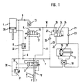
- Fig. 1 the circuit of a first embodiment of a sequence control according to the invention is shown.
- control valve 3 From the port P runs a feed line 1 with a filter 2 to a control valve 3, which is common to a rotary cylinder 4 and a pivot cylinder 5 for control.
- the control valve is designed as a 4/2 valve, which also includes a 2/2 valve with respect to control lines.
- the supply line 1 branches into a supply line 6 for the rotary cylinder and a supply line 7 for the swivel cylinder.
- the supply line 6 opens on the piston rod side in the rotary cylinder 4 and has a flow control valve 8.
- a return line 9 attaches to the rotary cylinder 4, which unites with a return line 10 of the swivel cylinder to form a common return line 11, which leads through the control valve 3 and a filter 12 to the connection T.
- a controllable first check valve 13 is used as the non-return valve, which is controlled via a first control line 14, which branches off from the supply line 6 of the rotary cylinder 4.
- the first check valve 13 closes in the direction of the port P.
- a pressure valve 15 is inserted into the control line 14.
- This pressure valve 15 is a 2/2 valve, which in its rest position blocks the first control line 14 with a built-in second check valve 16 in the direction of the first check valve 13.
- a valve control line 17 for the pressure valve 15 branches off from the control line 14. The pressure in this valve control line 17 acts on a restoring force, which is subject to the pressure valve 15, so that the pressure valve 15 opens when the pressure in the valve control line 17 assumes a value which exceeds the pressure of the restoring force.
- the restoring force is preferably set to a pressure threshold value of approximately 160 bar.
- the supply line 7 for the swivel cylinder 5 leads to the piston side of the swivel cylinder 5 via a valve 18.
- the return line 10 of the swivel cylinder 5 attaches to the swivel cylinder on the piston rod side and likewise leads to the common return line 11 via the valve 18.
- the piston 19 of the swivel cylinder 5 has a damping device 20 on.
- the return line 10 of the pivot cylinder 5 is divided into two sections, namely a first return branch 21 and a second return branch 22.
- the valve 24 is controlled via a second control line 25, which branches off from the supply line 7 of the pivot cylinder 5.
- a fourth check valve 26, which closes in the direction of the connection T, is inserted in the second control line 25.
- a restoring force which counteracts the action of the second control line 25 also acts on the valve 24.
- the rest position of the valve 24, in which the valve 24 blocks the second return branch 22, is thus maintained in that a control means via the second control line 25 the valve 24 acts, which exerts a pressure which is greater than the pressure of the restoring force.
- An outlet 27 for control means branches off between the fourth check valve 26 of the control line 25 and the controlled valve 24. This outflow leads to the side of the valve 24 opposite the mouth of the second control line 25, that is to say to the restoring force side of the valve 24.
- an orifice 28 is inserted which has a predetermined opening radius and can also be opened and closed. The opening radius of the orifice is matched to the restoring force of the valve 24, so that control means flows out of the area between the fourth check valve 26 and the valve 24 with a predetermined time constant to the restoring force side of the valve 24.
- a time of approximately 3 s is preferably set.
- the restoring force is preferably set at approximately 10 bar.
- the aperture 28 is closed.
- An opening of the diaphragm is preferably carried out coupled with a switchover of the common control valve 3. This switchover of the control valve 3 correlates, as will be described below, with the movement of the piston 29 of the rotary cylinder 4 through its top dead center.
- the control valve 3 switches over automatically when the piston 29 of the rotary cylinder 24 is retracted, that is to say moves at its top dead center.
- the sequence control has in particular a third control line 30 which branches off from the supply line 6 of the rotary cylinder 4 and controls a pressure valve 31.
- a pressure builds up in this third control line 30, which is sufficient to open the pressure valve 31 against a restoring force, so that a pressure acts on the control valve 3 via the continuation 32 of the third control line 30 Switching the control valve 3 against a restoring force.
- the control valve 3 is switched back again with the aid of a return line 33 which branches off from the return line 9.
- the sequence control according to FIG. 1 works as follows:
- Hydraulic oil is supplied to the swivel cylinder 5 on the piston side via the feed lines 1 and 7, so that the swivel cylinder 5 extends and swivels in the plow frame, while hydraulic oil on the piston rod side runs out of the swivel cylinder 5 via the return line 21, 10, 11.
- This pressure exceeds the threshold value predetermined by the restoring force of the pressure valve 15, so that the pressure valve 15 opens and thus also opens the first check valve 13 in the return line 9 of the rotary cylinder 4 via the control line 14.
- the rotary cylinder 4 can thus retract when the pivot cylinder 5 is extended.
- the common control valve 3 switches over, so that the return line 11 now becomes the supply line.
- the hydraulic oil flows through the return line 11 and the first check valve 13, which only blocks in the direction of the connection T, on the piston side into the rotary cylinder 4, so that this rotary cylinder 4 extends. This initiates the second rotation phase for rotating the plow frame.
- This control medium pad slowly flows through the drain 27 and the orifice 28 to the return side of the valve 24 from, so that the valve 24 only gradually moves into its open position.
- the rotary cylinder 4 is almost completely extended.
- the swivel cylinder 5 can therefore only retract and pivot the plow frame out again when the rotation of the plow frame is almost complete, so that the pivoted plow frame cannot interfere with the rotary movement of the plow frame.
- the sequence of retracting and extending the rotary cylinder 4 and the pivot cylinder 5 can thus be predetermined and controlled without pressure drops occurring in the rotary cylinder 4 or malfunctions in the control system being feared.
- a pressure drop at the rotary cylinder is avoided at all times by the pressure valve 15 being inserted in the first control line 14, that is to say outside the supply line 6. After the plow frame has been rotated, the control valve 3 switches over again.
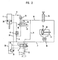
- FIG. 2 shows a second exemplary embodiment of a sequence control according to the invention:
- the sequence control according to FIG. 2 largely corresponds to the sequence control according to FIG. 1.
- the same components are therefore designated in FIG. 2 with the same reference numbers as in FIG. 1.
- the return line 10 of the swivel cylinder 5 has no return branches 21, 22 and the controlled valve 24 in the return line 10 is replaced by another controlled valve 34.
- This controlled valve 34 is a rotary valve, which is approximately 180 ° is rotatable.
- the passages of this rotary valve 34 are arranged so that it is open during the extension of the pivot cylinder 5 to allow the extension.
- the rotary cylinder 4 begins to retract, whereby the plow rotation shaft of the plow frame is rotated.
- the rotary valve 34 is coupled to this plow rotary shaft, namely the rotary valve 34 is driven by the plow rotary shaft.
- the rotary valve 34 closes and only opens again when the plow frame only has to be rotated approximately 20 ° to 30 ° by the end of the rotation.
- the rotary valve 34 is open. It closes after turning the plow frame by about 20 to 30 ° and opens after turning the plow frame by about 150 to 160 °.
- valve control also ensures that the plow frame is pivoted in before it is rotated, and that the plow frame is only pivoted out when the rotation of the plow frame has already progressed to such an extent that the pivoting out of the plow frame no longer disrupts the rotary movement. Otherwise, the sequence control according to FIG. 2 operates in accordance with the sequence control according to FIG. 1.
- the opening pistons of the valves 13 and 18 are each provided with orifice bores in order to prevent the valves from opening in the event of a leak.
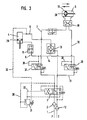
- FIG. 3 shows a third exemplary embodiment of a circuit according to the invention. Like or in the following figures, the same or corresponding components are identified by the same reference numerals as in FIG. 1.
- valve arrangements 15 to 17 and 24 to 28 of the exemplary embodiment according to FIG. 1 are missing. Instead, the sequence control in the exemplary embodiment according to FIG. 3 is implemented with other elements.
- the return lines 9, 10 of the cylinders 4 and 5, which unite to form the return line 11, are equipped in the area of their union with a 3/2-way valve, which functions as a control valve arrangement 36 for regulating the return flow.
- a corresponding control valve arrangement 37 is found in the feed lines 1 and 6, 7, since these feed lines become return lines after the control valve 3 has been switched over in the second rotation phase of the plow.
- the control valve arrangements 36, 37 are controlled via control lines 38, 39. In the switching position of the control valve 3 shown, it is clear that the control line 38 for the first turning phase of the reversible plow is connected to the return line 10 of the pivot cylinder 5, so that the control valve arrangement 36 is actuated into the switching position 1 by the hydraulic fluid flowing out of the pivot cylinder 5 .
- the control valve arrangement 36 or 37 has a flow path for the return of the rotary cylinder 4 and a check valve for the return of the pivot cylinder 5 for its switching position 0.
- Position 1 is a flow for the return of the swivel cylinder 5 and a block for the return of the rotary cylinder 4.
- hydraulic fluid is pumped into the two cylinders 4, 5 via the feed line 1.
- the check valves 13 and 18 are open or are opened (control line 14), so that hydraulic fluid flowing out of both cylinders 4, 5 is applied to the control valve arrangement 36.
- the outflowing hydraulic medium from the pivot cylinder 5 is preferred, however, since it can actuate the control valve arrangement 36 into the switching position 1 via the control line 38, so that only the outflow for the hydraulic medium from the pivot cylinder 5 is free. This is the case as long as hydraulic fluid flowing out of the pivot cylinder 5 is present in the control line 38, i.e. as long as hydraulic fluid flows out of the swivel cylinder 5 at all.
- control valve 3 To initiate the second phase of rotation, the control valve 3 is switched. As a result, the control valve arrangement 37 is set to the corresponding function that the control valve arrangement 36 previously had. At this control valve arrangement 37, the hydraulic fluid flowing out of the rotary cylinder 4 is preferred via the control line 39, so that in the second rotary phase the rotary cylinder first rotates the plow frame before the plow frame is pivoted out again in strict succession by the pivot cylinder 5.
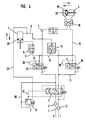
- the circuit according to FIG. 4 corresponds essentially to the embodiment of FIG. 3.
- the sequence control according to FIG. 3 becomes a priority circuit with superimposed parallel operation. Hydraulic fluid can flow out of the respective subordinate cylinders 4, 5 via the orifices 40 and 41, so that this subordinate cylinder also moves, albeit in a creeper gear.
- Figure 5 shows a fourth embodiment of a circuit according to the invention.
- the exemplary embodiment according to FIG. 5 is a sequential circuit corresponding to the exemplary embodiment of FIG. 3. Only the control valve arrangements 36, 37 are implemented differently in the exemplary embodiment according to FIG. 5 than in the exemplary embodiment according to FIG. 3. Otherwise, the exemplary embodiments are functionally the same.
- FIG. 6 shows an exemplary embodiment with the components according to FIG. 5 as a priority circuit corresponding to the exemplary embodiment according to FIG. 4.
- panels 40, 41 are also present in this exemplary embodiment according to FIG. 6.
Landscapes
- Life Sciences & Earth Sciences (AREA)
- Engineering & Computer Science (AREA)
- Mechanical Engineering (AREA)
- Soil Sciences (AREA)
- Environmental Sciences (AREA)
- Fluid-Pressure Circuits (AREA)
- Fats And Perfumes (AREA)
- Communication Control (AREA)
- Small-Scale Networks (AREA)
- Ship Loading And Unloading (AREA)
Priority Applications (1)
| Application Number | Priority Date | Filing Date | Title |
|---|---|---|---|
| AT90108321T ATE93355T1 (de) | 1989-09-05 | 1990-05-02 | Folgesteuerung bzw. vorrangschaltung fuer einen drehpflug mit rahmeneinschwenkung. |
Applications Claiming Priority (2)
| Application Number | Priority Date | Filing Date | Title |
|---|---|---|---|
| DE8910585 | 1989-09-05 | ||
| DE8910585U | 1989-09-05 |
Publications (3)
| Publication Number | Publication Date |
|---|---|
| EP0416206A2 true EP0416206A2 (fr) | 1991-03-13 |
| EP0416206A3 EP0416206A3 (en) | 1991-11-13 |
| EP0416206B1 EP0416206B1 (fr) | 1993-08-25 |
Family
ID=6842566
Family Applications (1)
| Application Number | Title | Priority Date | Filing Date |
|---|---|---|---|
| EP90108321A Expired - Lifetime EP0416206B1 (fr) | 1989-09-05 | 1990-05-02 | Contrôle de séquence prioritaire pour charrue reversible hydraulique |
Country Status (3)
| Country | Link |
|---|---|
| EP (1) | EP0416206B1 (fr) |
| AT (1) | ATE93355T1 (fr) |
| DE (1) | DE59002461D1 (fr) |
Cited By (4)
| Publication number | Priority date | Publication date | Assignee | Title |
|---|---|---|---|---|
| DE4311275A1 (de) * | 1993-04-06 | 1994-10-13 | Weber Hydraulik Gmbh | Folgesteuerung bzw. Vorrangschaltung für einen Drehpflug mit Pflugrahmeneinschwenkung |
| EP0890748A1 (fr) * | 1997-07-10 | 1999-01-13 | Kuhn-Huard S.A. | Dispositif de commande d'une charrue |
| NL1020827C2 (nl) * | 2002-06-11 | 2003-12-15 | Actuant Corp | Ploegwentelinrichting. |
| EP1757179A1 (fr) | 2005-08-25 | 2007-02-28 | Weber-Hydraulik GmbH | Contrôle hydraulique pour une charrue réversible |
Families Citing this family (1)
| Publication number | Priority date | Publication date | Assignee | Title |
|---|---|---|---|---|
| CN108626188B (zh) * | 2018-05-18 | 2020-07-03 | 特尔阀门高科技有限公司 | 一种自动控制阀门 |
Family Cites Families (5)
| Publication number | Priority date | Publication date | Assignee | Title |
|---|---|---|---|---|
| DE3123727C2 (de) * | 1981-06-15 | 1989-09-21 | Emil Weber Fabrik für Ölhydraulik GmbH & Co, 7129 Güglingen | Steuervorrichtung für das Verschwenken eines Drehpfluges |
| DE3218631A1 (de) * | 1982-05-18 | 1983-11-24 | Rabewerk Heinrich Clausing, 4515 Bad Essen | Drehpflug mit einer waehrend des ackerns zu betaetigenden schnittbreiteneinstellung |
| NO153516C (no) * | 1984-01-18 | 1986-04-09 | Kverneland As | Vende- og innstillingsmekanisme. |
| DE3513096A1 (de) * | 1985-04-12 | 1986-10-16 | Maschinenfabriken Bernard Krone Gmbh, 4441 Spelle | Anbaupflug |
| DE3908985A1 (de) * | 1989-03-18 | 1990-09-27 | Integral Hydraulik Co | Hydraulische schaltung fuer einen anbaudrehpflug |
-
1990
- 1990-05-02 AT AT90108321T patent/ATE93355T1/de not_active IP Right Cessation
- 1990-05-02 DE DE90108321T patent/DE59002461D1/de not_active Expired - Lifetime
- 1990-05-02 EP EP90108321A patent/EP0416206B1/fr not_active Expired - Lifetime
Cited By (6)
| Publication number | Priority date | Publication date | Assignee | Title |
|---|---|---|---|---|
| DE4311275A1 (de) * | 1993-04-06 | 1994-10-13 | Weber Hydraulik Gmbh | Folgesteuerung bzw. Vorrangschaltung für einen Drehpflug mit Pflugrahmeneinschwenkung |
| EP0890748A1 (fr) * | 1997-07-10 | 1999-01-13 | Kuhn-Huard S.A. | Dispositif de commande d'une charrue |
| FR2765924A1 (fr) * | 1997-07-10 | 1999-01-15 | Kuhn Huard Sa | Dispositif permettant de commander deux verins |
| NL1020827C2 (nl) * | 2002-06-11 | 2003-12-15 | Actuant Corp | Ploegwentelinrichting. |
| EP1371855A1 (fr) | 2002-06-11 | 2003-12-17 | Actuant Corporation | Dispositif de retournement d'une charrue réversible |
| EP1757179A1 (fr) | 2005-08-25 | 2007-02-28 | Weber-Hydraulik GmbH | Contrôle hydraulique pour une charrue réversible |
Also Published As
| Publication number | Publication date |
|---|---|
| ATE93355T1 (de) | 1993-09-15 |
| EP0416206B1 (fr) | 1993-08-25 |
| DE59002461D1 (de) | 1993-09-30 |
| EP0416206A3 (en) | 1991-11-13 |
Similar Documents
| Publication | Publication Date | Title |
|---|---|---|
| AT390347B (de) | Umkehr- und einstellmechanismus | |
| EP1355065B1 (fr) | Commande hydraulique | |
| DE1528550A1 (de) | Hydraulisches Zufuehrungs- und Steuersystem | |
| EP0465474B1 (fr) | Agencement de commande de pompes a liquides epais a deux cylindres | |
| EP0137186A2 (fr) | Système hydraulique avec une pompe à débit constant et une valve de priorité | |
| DE3218631C2 (fr) | ||
| DE3243330A1 (de) | Bearbeitungsgeraet | |
| DE4438994A1 (de) | Hydraulikvorrichtung | |
| EP0416206B1 (fr) | Contrôle de séquence prioritaire pour charrue reversible hydraulique | |
| DE69622098T2 (de) | Vorrichtung zum Verdrehen eines Pfluges | |
| DE69610922T2 (de) | Hydraulisches sicherheitsbremsventil | |
| DE4311275C2 (de) | Folgesteuerung oder Vorrangschaltung für einen Drehpflug mit Pflugrahmeneinschwenkung | |
| DE3908985C2 (fr) | ||
| DE19548943B4 (de) | Ventilanordnung | |
| DE1650267B2 (de) | Hydraulische vorrichtung zur steuerung des druckmittelflusses zu einem einen doppeltund einen einfachwirkenden hydrozylinder aufweisenden hydraulischen system | |
| EP4275465B1 (fr) | Dispositif de réglage hydraulique | |
| AT502034B1 (de) | Hydraulische steuerung für einen drehpflug | |
| DE60306847T2 (de) | Pflugwendevorrichtung | |
| DE60019743T2 (de) | Hydraulische Vorrichtung zum Steuern eines Vorsteuerdrucks | |
| DE2517421C3 (de) | Mechanisch-hydraulische Folgesteueranordnung für ein Fahrwerk eines Luftfahrzeuges | |
| DE6803021U (de) | Vorrichtung felgesteuerung fuer einen hydraulischen motor | |
| DE4243343C2 (de) | Steuervorrichtung für das Verschwenken eines Drehpfluges | |
| DE19620664C1 (de) | Hydraulische Steuerung, insbesondere zum Ansteuern des Drehwerks eines Baggers | |
| DE2911326A1 (de) | Druckentlastungsvorrichtung | |
| DE3113516C2 (fr) |
Legal Events
| Date | Code | Title | Description |
|---|---|---|---|
| PUAI | Public reference made under article 153(3) epc to a published international application that has entered the european phase |
Free format text: ORIGINAL CODE: 0009012 |
|
| 17P | Request for examination filed |
Effective date: 19910102 |
|
| AK | Designated contracting states |
Kind code of ref document: A2 Designated state(s): AT BE CH DE DK ES FR GB GR IT LI LU NL SE |
|
| RBV | Designated contracting states (corrected) |
Designated state(s): AT BE CH DE DK FR GB IT LI LU NL SE |
|
| PUAL | Search report despatched |
Free format text: ORIGINAL CODE: 0009013 |
|
| AK | Designated contracting states |
Kind code of ref document: A3 Designated state(s): AT BE CH DE DK ES FR GB GR IT LI LU NL SE |
|
| 17Q | First examination report despatched |
Effective date: 19920214 |
|
| GRAA | (expected) grant |
Free format text: ORIGINAL CODE: 0009210 |
|
| ITF | It: translation for a ep patent filed | ||
| AK | Designated contracting states |
Kind code of ref document: B1 Designated state(s): AT BE CH DE DK FR GB IT LI LU NL SE |
|
| REF | Corresponds to: |
Ref document number: 93355 Country of ref document: AT Date of ref document: 19930915 Kind code of ref document: T |
|
| REF | Corresponds to: |
Ref document number: 59002461 Country of ref document: DE Date of ref document: 19930930 |
|
| ET | Fr: translation filed | ||
| GBT | Gb: translation of ep patent filed (gb section 77(6)(a)/1977) |
Effective date: 19931029 |
|
| PG25 | Lapsed in a contracting state [announced via postgrant information from national office to epo] |
Ref country code: DK Effective date: 19940502 Ref country code: GB Effective date: 19940502 |
|
| PG25 | Lapsed in a contracting state [announced via postgrant information from national office to epo] |
Ref country code: CH Effective date: 19940531 Ref country code: BE Effective date: 19940531 Ref country code: LU Free format text: LAPSE BECAUSE OF NON-PAYMENT OF DUE FEES Effective date: 19940531 Ref country code: LI Effective date: 19940531 |
|
| PLBE | No opposition filed within time limit |
Free format text: ORIGINAL CODE: 0009261 |
|
| STAA | Information on the status of an ep patent application or granted ep patent |
Free format text: STATUS: NO OPPOSITION FILED WITHIN TIME LIMIT |
|
| 26N | No opposition filed | ||
| BERE | Be: lapsed |
Owner name: WEBER-HYDRAULIK G.M.B.H. Effective date: 19940531 |
|
| GBPC | Gb: european patent ceased through non-payment of renewal fee |
Effective date: 19940502 |
|
| EAL | Se: european patent in force in sweden |
Ref document number: 90108321.2 |
|
| REG | Reference to a national code |
Ref country code: CH Ref legal event code: PL |
|
| PGFP | Annual fee paid to national office [announced via postgrant information from national office to epo] |
Ref country code: SE Payment date: 19990430 Year of fee payment: 10 |
|
| PG25 | Lapsed in a contracting state [announced via postgrant information from national office to epo] |
Ref country code: SE Free format text: LAPSE BECAUSE OF NON-PAYMENT OF DUE FEES Effective date: 20000503 |
|
| PGFP | Annual fee paid to national office [announced via postgrant information from national office to epo] |
Ref country code: NL Payment date: 20000524 Year of fee payment: 11 |
|
| EUG | Se: european patent has lapsed |
Ref document number: 90108321.2 |
|
| PG25 | Lapsed in a contracting state [announced via postgrant information from national office to epo] |
Ref country code: NL Free format text: LAPSE BECAUSE OF NON-PAYMENT OF DUE FEES Effective date: 20011201 |
|
| NLV4 | Nl: lapsed or anulled due to non-payment of the annual fee |
Effective date: 20011201 |
|
| PGFP | Annual fee paid to national office [announced via postgrant information from national office to epo] |
Ref country code: IT Payment date: 20090527 Year of fee payment: 20 Ref country code: FR Payment date: 20090519 Year of fee payment: 20 Ref country code: DE Payment date: 20090401 Year of fee payment: 20 Ref country code: AT Payment date: 20090522 Year of fee payment: 20 |
|
| PG25 | Lapsed in a contracting state [announced via postgrant information from national office to epo] |
Ref country code: DE Free format text: LAPSE BECAUSE OF EXPIRATION OF PROTECTION Effective date: 20100502 |