EP0416207A2 - Optical cable - Google Patents
Optical cable Download PDFInfo
- Publication number
- EP0416207A2 EP0416207A2 EP90108613A EP90108613A EP0416207A2 EP 0416207 A2 EP0416207 A2 EP 0416207A2 EP 90108613 A EP90108613 A EP 90108613A EP 90108613 A EP90108613 A EP 90108613A EP 0416207 A2 EP0416207 A2 EP 0416207A2
- Authority
- EP
- European Patent Office
- Prior art keywords
- optical fiber
- strain relief
- wires
- relief elements
- sheath
- Prior art date
- Legal status (The legal status is an assumption and is not a legal conclusion. Google has not performed a legal analysis and makes no representation as to the accuracy of the status listed.)
- Granted
Links
Images



Classifications
-
- G—PHYSICS
- G02—OPTICS
- G02B—OPTICAL ELEMENTS, SYSTEMS OR APPARATUS
- G02B6/00—Light guides; Structural details of arrangements comprising light guides and other optical elements, e.g. couplings
- G02B6/44—Mechanical structures for providing tensile strength and external protection for fibres, e.g. optical transmission cables
- G02B6/4401—Optical cables
- G02B6/4407—Optical cables with internal fluted support member
-
- G—PHYSICS
- G02—OPTICS
- G02B—OPTICAL ELEMENTS, SYSTEMS OR APPARATUS
- G02B6/00—Light guides; Structural details of arrangements comprising light guides and other optical elements, e.g. couplings
- G02B6/44—Mechanical structures for providing tensile strength and external protection for fibres, e.g. optical transmission cables
- G02B6/4401—Optical cables
- G02B6/4429—Means specially adapted for strengthening or protecting the cables
-
- G—PHYSICS
- G02—OPTICS
- G02B—OPTICAL ELEMENTS, SYSTEMS OR APPARATUS
- G02B6/00—Light guides; Structural details of arrangements comprising light guides and other optical elements, e.g. couplings
- G02B6/44—Mechanical structures for providing tensile strength and external protection for fibres, e.g. optical transmission cables
- G02B6/4401—Optical cables
- G02B6/4429—Means specially adapted for strengthening or protecting the cables
- G02B6/443—Protective covering
- G02B6/4431—Protective covering with provision in the protective covering, e.g. weak line, for gaining access to one or more fibres, e.g. for branching or tapping
-
- G—PHYSICS
- G02—OPTICS
- G02B—OPTICAL ELEMENTS, SYSTEMS OR APPARATUS
- G02B6/00—Light guides; Structural details of arrangements comprising light guides and other optical elements, e.g. couplings
- G02B6/44—Mechanical structures for providing tensile strength and external protection for fibres, e.g. optical transmission cables
- G02B6/4401—Optical cables
- G02B6/4429—Means specially adapted for strengthening or protecting the cables
- G02B6/44382—Means specially adapted for strengthening or protecting the cables the means comprising hydrogen absorbing materials
Definitions
- an optical waveguide cable has a central element in the middle, around which the individual optical waveguide wires are arranged in the form of a layer.
- Each optical fiber has one or more glass fibers as optical fibers.
- the whole of the optical waveguide wires is surrounded by a sheath that can be produced by winding.
- the cavities between the optical fiber cores can be filled with fillers such as petrolatum.
- Strain relief elements are generally arranged around the sheath for the optical fibers: they are generally stranded. The strain relief elements are glued to a tape surrounding the strain relief elements or directly to an outer jacket.
- the invention has for its object to provide an optical fiber cable that enables the exposure of the optical fiber wires (for assembly purposes or for repair purposes) in a simple manner. This object is achieved by an optical fiber cable with the features of claim 1.
- the figure shows the cross section of an optical fiber cable according to the invention.
- the fiber optic cable of Figure 1 consists of a central element 1, around which the fiber optic wires are arranged.
- the optical waveguide wires consist of an optical waveguide 2 and a sheath 3.
- not only optical fiber cores are arranged around the central element 1, but also the two tear threads 4 and 5.
- the tear threads (4, 5) generally have a smaller cross section than the optical fiber cores. although they are shown in the figures with the same cross section for the sake of simplicity.
- the tear threads generally consist of twisted threads.
- the optical waveguide wires and the tear threads are surrounded by a soul winding 6.
- the soul winding consists, for example, of wound paper or plastic tapes or, to achieve special longitudinal water tightness, of swellable tapes.
- the soul winding 6 is surrounded by strain relief elements 7. which consist for example of glass or aramid yarn.
- the outer jacket 8 made of plastic follows the strain relief elements 7.
- the strain relief elements 7 are generally glued to the outer jacket 8.
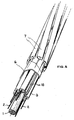
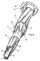
- FIG. 3 again shows the cable of FIG. 1 in a perspective view and in the cut state.
- Figure 4 shows a second embodiment of the invention in section.
- the optical fiber cable of FIG. 4 consists of a central element 1 and optical fiber cores which surround the central element 1.
- the optical waveguide wires consist of a plurality of optical waveguides 2, which are surrounded by a sheath 3.
- the optical fiber cores are surrounded by a soul winding 6. which consists of tapes as in the first embodiment. Tear threads (4. 5) are also provided in the optical fiber cable of FIG. 4. which are not arranged in the position of the optical waveguides in the second exemplary embodiment. but in the gusset spaces 9, which are present between the optical fiber cores and the soul winding 6.
- the soul winding 6 is surrounded by an outer jacket 8.
- FIG. 5 shows, the tear threads 4 and 5 are arranged stranded.
- FIG. 6 shows the optical fiber cable of FIG. 4 in a perspective view.
- FIG. 7 shows a third exemplary embodiment of the invention in a sectional illustration.
- the optical waveguide cable of FIG. 7 consists of a central element 1, around which optical waveguide wires are in turn arranged.
- the optical fiber cores consist of two optical fibers 2, which are surrounded by a sheath 3.
- the central element 1 in the exemplary embodiment in FIG. 7 is also surrounded by two copper cores (10) which are stranded together.
- the optical waveguide wires and the copper wires are surrounded by a core winding 6 which, as in the other exemplary embodiments, consists of ribbons.
- the soul winding 6 is surrounded by strain relief elements 7, which can be arranged in one or more layers. In the exemplary embodiment in FIG. 7, two layers of strain relief elements 7 are present. The strain relief elements of the two layers are offset from one another.
- the tear threads 4 and 5 are located between strain relief elements 7.
- the tear threads are arranged in the outer layer of the two layers of the strain relief elements.
- the tear threads are stranded with the strain relief elements in the outer layer in order to completely detach the outer layer of the strain relief elements bonded to the cable sheath together with the sheath from the inner part of the cable when the cable is cut.
- the strain relief elements 7 are surrounded by a metallic sheath 11 which, for example, consists of a longitudinally running band.
- the band is made of aluminum or steel, for example.
- FIG. 8 shows that the tear threads 4 and 5 of the optical waveguide cable of FIG. 7 are arranged in a stranded manner.
- FIG. 9 shows a perspective illustration of the optical waveguide cable of FIG. 7 in the cut state.
- tears 4 and 5 are torn, the fiber optic wires are exposed in a simple manner in all cases. This enables cable assembly.
Landscapes
- Physics & Mathematics (AREA)
- General Physics & Mathematics (AREA)
- Optics & Photonics (AREA)
- Communication Cables (AREA)
- Light Guides In General And Applications Therefor (AREA)
- Optical Fibers, Optical Fiber Cores, And Optical Fiber Bundles (AREA)
- Ropes Or Cables (AREA)
- Agricultural Chemicals And Associated Chemicals (AREA)
- Glass Compositions (AREA)
- Photoreceptors In Electrophotography (AREA)
Abstract
Bei Lichtwellenleiterkabeln mit einem Außenmantel und mit Lichtwellenleiteradern (2), die um ein Zentralelement (1) angeordnet sind, ist vorgesehen, daß Reißfäden (4,5) zwischen den Lichtwellenleiteradern oder im Bereich zwischen den Lichtwellenleitern und dem Außenmantel (8) vorgesehen sind und daß die Reißfäden (4,5) verseilt sind.For fiber optic cables with an outer jacket and with fiber optic wires (2), which are arranged around a central element (1), it is provided that tear threads (4,5) are provided between the fiber optic wires or in the area between the fiber optics and the outer jacket (8) and that the tear threads (4,5) are stranded.
Description
Ein Lichtwellenleiterkabel hat bekanntlich in der Mitte ein Zentralelement, um das die einzelnen Lichtwellenleiteradern in Gestalt einer Lage verteilt angeordnet sind. Jede Lichtwellenleiterader weist eine oder mehrere Glasfasern als Lichtwellenleiter auf. Die Gesamtheit der Lichtwellenleiteradern ist von einer Hülle umgeben, die durch Aufwickeln hergestellt werden kann. Die Hohlräume zwischen den Lichtwellenleiteradern können durch Füllmassen wie Petrolaten ausgefüllt sein. Um die Hülle für die Lichtwellenleiteradern sind im allgemeinen Zugentlastungselemente angeordnet: die im allgemeinen verseilt sind. Die Zugentlastungselemente sind mit einem die Zugentlastungselemente umgebenden Band oder direkt mit einem Außenmantel verklebt.As is known, an optical waveguide cable has a central element in the middle, around which the individual optical waveguide wires are arranged in the form of a layer. Each optical fiber has one or more glass fibers as optical fibers. The whole of the optical waveguide wires is surrounded by a sheath that can be produced by winding. The cavities between the optical fiber cores can be filled with fillers such as petrolatum. Strain relief elements are generally arranged around the sheath for the optical fibers: they are generally stranded. The strain relief elements are glued to a tape surrounding the strain relief elements or directly to an outer jacket.
Bei der Montage von Lichtwellenleiterkabeln müssen die Lichtwellenleiter freigelegt werden, um die Lichtwellenleiteradern anschließen zu können. Die Lichtwellenleiteradern müssen manchmal sogar in einer Länge von mehreren Metern freigelegt und damit von den umgebenden Elementen des Lichtwellenleiterkabels befreit werden. Der Erfindung liegt die Aufgabe zugrunde, ein Lichtwellenleiterkabel anzugeben, welches in einfacher Weise das Freilegen der Lichtwellenleiteradern (zu Montagezwecken oder zu Reparaturzwecken) ermöglicht. Diese Aufgabe wird erfindungsgemäß durch ein Lichtwellenleiterkabel mit den Merkmalen des Anspruchs 1 gelöst.When installing fiber optic cables, the fiber optic cables must be exposed in order to be able to connect the fiber optic cables. The fiber optic wires sometimes even have to be exposed several meters in length and thus be freed from the surrounding elements of the fiber optic cable. The invention has for its object to provide an optical fiber cable that enables the exposure of the optical fiber wires (for assembly purposes or for repair purposes) in a simple manner. This object is achieved by an optical fiber cable with the features of
Die Erfindung wird im folgenden an Ausführungsbeispielen erläutert.The invention is explained below using exemplary embodiments.
Die Figur zeigt den Querschnitt eines Lichtwellenleiterkabels nach der Erfindung. Das Lichtwellenleiterkabel der Figur 1 besteht aus einem Zentralelement 1, um das Lichtwellenleiteradern angeordnet sind. Die Lichtwellenleiteradern bestehen gemäß der Figur 1 aus einem Lichtwellenleiter 2 und einer Umhüllung 3. In der Hülle 3 befindet sich im allgemeinen eine Füllmasse, in die der Lichtwellenleiter 2 eingebettet ist. Um das Zentralelement 1 sind bei der Ausführungsform der Figur 1 nicht nur Lichtwellenleiteradern angeordnet, sondern auch die beiden Reißfäden 4 und 5. Die Reißfäden (4, 5) haben im allgemeinen einen kleineren Querschnitt als die Lichtwellenleiteradern. obwohl sie in den Figuren der Einfachheit halber mit gleichem Querschnitt dargestellt sind. Die Reißfäden bestehen im allgemeinen aus verzwirnten Fäden.The figure shows the cross section of an optical fiber cable according to the invention. The fiber optic cable of Figure 1 consists of a
Wie die Figur 1 weiter zeigt, sind die Lichtwellenleiteradern und die Reißfäden von einer seelenbewicklung 6 umgeben. Die Seelenbewicklung besteht beispielswweise aus aufgewickelten Papier- oder Kunststoffbändern oder zur Erzielung besonderer Längswasserdichtigkeit aus quellfähigen Bändern. Die Seelenbewicklung 6 ist gemäß der Figur 1 von Zugentlastungselementen 7 umgeben. die beispielsweise aus Glas oder Aramidgarn bestehen. Auf die Zugentlastungselemente 7 folgt der Außenmantel 8 aus Kunststoff. Die Zugentlastungselemente 7 sind im allgemeinen mit dem Außenmantel 8 verklebt.As FIG. 1 further shows, the optical waveguide wires and the tear threads are surrounded by a soul winding 6. The soul winding consists, for example, of wound paper or plastic tapes or, to achieve special longitudinal water tightness, of swellable tapes. According to FIG. 1, the soul winding 6 is surrounded by
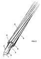
Wie die Figur 2 erkennen läßt. sind bei der Anordnung der Figur 1 die Reißfäden 4 und 5 erfindungsgemäß verseilt und zwar in der gleichen Lage wie die Lichtwellenleiteradern. Die Figur 3 zeigt nochmals das Kabel der Figur 1 in perspektivischer Darstellung und im aufgeschnittenen Zustand.As can be seen in Figure 2. 1, the
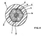
Die Figur 4 zeigt ein zweites Ausführungsbeispiel der Erfindung im Schnitt. Das Lichtwellenleiterkabel der Figur 4 besteht aus einem Zentralelement 1 und Lichtwellenleiteradern, die das Zentralelement 1 umgeben. Die Lichtwellenleiteradern bestehen im Ausführungsbeispiel der Figur 4 aus mehreren Lichtwellenleitern 2, die von einer Hülle 3 umgeben sind. Die Lichtwellenleiteradern sind von einer Seelenbewicklung 6 umgeben. die wie im ersten Ausführungsbeispiel aus Bändern besteht. Bei dem Lichtwellenleiterkabel der Figur 4 sind ebenfalls Reißfäden (4. 5 ) vorgesehen. die im zweiten Ausführungsbeispiel nicht in der Lage der Lichtwellenleiter angeordnet sind. sondern in den Zwickelräumen 9, die zwischen den Lichtwellenleiteradern und der Seelenbewicklung 6 vorhanden sind. Die Seelenbewicklung 6 ist von einem Außenmantel 8 umgeben.Figure 4 shows a second embodiment of the invention in section. The optical fiber cable of FIG. 4 consists of a
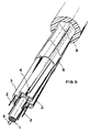
Wie die Figur 5 zeigt, sind die Reißfäden 4 und 5 verseilt angeordnet. Die Figur 6 zeigt das Lichtwellenleiterkabel der Figur 4 in perspektivischer Darstellung.As FIG. 5 shows, the
Die Figur 7 zeigt ein drittes Ausführungsbeispiel der Erfindung in Schnittdarstellung. Das Lichtwellenleiterkabel der Figur 7 besteht aus einem Zentralelement 1, um das wiederum Lichtwellenleiteradern angeordnet sind.FIG. 7 shows a third exemplary embodiment of the invention in a sectional illustration. The optical waveguide cable of FIG. 7 consists of a
Die Lichtwellenleiteradern bestehen beim Lichtwellenleiterkabel der Figur 7 aus zwei Lichtwellenleitern 2, die von einer Hülle 3 umgeben sind. Außer von Lichtwellenleiteradern ist beim Ausführungsbeispiel der Figur 7 das Zentralelement 1 auch noch von zwei Kupferadern (10) umgeben, die miteinander verseilt sind. Die Lichtwellenleiteradern und die Kupferadern sind von einer Seelenbewicklung 6 umgeben, die wie in den anderen Ausführungsbeispielen aus Bändern besteht. Die Seelenbewicklung 6 ist von Zugentlastungselementen 7 umgeben, die in einer oder mehreren Lagen angeordnet sein können. Im Ausführungsbeispiel der Figur 7 sind zwei Lagen Zugentlastungselemente 7 vorhanden. Die Zugentlastungselemente der beiden Lagen sind gegeneinander versetzt. Die Reißfäden 4 und 5 befinden sich im Ausführungsbeispiel der Figur 7 zwischen Zugentlastungselementen 7. Im Ausführungsbeispiel der Figur 7 sind die Reißfäden in der äußeren Lage der beiden Lagen der Zugentlastungselemente angeordnet. Die Reißfäden sind dagegen verseilt mit den Zugentlastungselementen in der äußeren Lage angeordnet, um beim Auftrennen des Kabels die mit dem Kabelmantel verklebte äußere Lage der Zugentlastungselemente zusammen mit dem Mantel vollständig vom Innenteil des Kabels zu lösen.In the case of the optical fiber cable of FIG. 7, the optical fiber cores consist of two
Beim Ausführungsbeispiel der Figur 7 sind die Zugentlastungselemente 7 von einer metallischen Hülle 11 umgeben, die beispielsweise aus einem längslaufenden Band besteht. Das Band besteht beispielsweise aus Aluminium oder Stahl.In the exemplary embodiment in FIG. 7, the
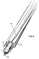
Die Figur 8 zeigt, daß die Reißfäden 4 und 5 des Lichtwellenleiterkabels der Figur 7 verseilt angeordnet sind. Die Figur 9 zeigt eine perspektivische Darstellung des Lichtwellenleiterkabels der Figur 7 im aufgeschnittenen Zustand.FIG. 8 shows that the
Wird an den Reißfäden 4 und 5 gerissen, so werden in sämtlichen Fällen die Lichtwellenleiteradern in einfacher Weise freigelegt. Dadurch wird eine Kabelmontage ermöglicht.If
Claims (9)
Applications Claiming Priority (2)
| Application Number | Priority Date | Filing Date | Title |
|---|---|---|---|
| DE3929215A DE3929215C2 (en) | 1989-09-02 | 1989-09-02 | Fiber optic cable |
| DE3929215 | 1989-09-02 |
Publications (3)
| Publication Number | Publication Date |
|---|---|
| EP0416207A2 true EP0416207A2 (en) | 1991-03-13 |
| EP0416207A3 EP0416207A3 (en) | 1991-12-18 |
| EP0416207B1 EP0416207B1 (en) | 1995-09-27 |
Family
ID=6388524
Family Applications (1)
| Application Number | Title | Priority Date | Filing Date |
|---|---|---|---|
| EP90108613A Expired - Lifetime EP0416207B1 (en) | 1989-09-02 | 1990-05-08 | Optical cable |
Country Status (6)
| Country | Link |
|---|---|
| EP (1) | EP0416207B1 (en) |
| AT (1) | ATE128558T1 (en) |
| DD (1) | DD299206A5 (en) |
| DE (2) | DE3929215C2 (en) |
| ES (1) | ES2077604T3 (en) |
| FI (1) | FI904274A7 (en) |
Cited By (3)
| Publication number | Priority date | Publication date | Assignee | Title |
|---|---|---|---|---|
| GB2270995A (en) * | 1992-09-23 | 1994-03-30 | Telephone Cables Ltd | Fibre optic cable |
| US6088499A (en) * | 1997-09-30 | 2000-07-11 | Siecor Corporation | Fiber optic cable with ripcord |
| US6813421B2 (en) | 2001-12-26 | 2004-11-02 | Corning Cable Systems Llc | Fiber optic cable having a ripcord |
Families Citing this family (1)
| Publication number | Priority date | Publication date | Assignee | Title |
|---|---|---|---|---|
| DE19609637A1 (en) * | 1996-03-12 | 1997-09-18 | Siemens Ag | Cable e.g. for telecommunications |
Family Cites Families (6)
| Publication number | Priority date | Publication date | Assignee | Title |
|---|---|---|---|---|
| GB1448793A (en) * | 1974-05-31 | 1976-09-08 | Post Office | Optical cables |
| GB1479427A (en) * | 1975-02-05 | 1977-07-13 | Bicc Ltd | Opticle cables |
| DE2532209C2 (en) * | 1975-07-16 | 1984-08-30 | Siemens AG, 1000 Berlin und 8000 München | Optical cable |
| DE2728658A1 (en) * | 1977-06-24 | 1979-01-04 | Siemens Ag | Optical cable of several plastic sheathed fibres - has at least one support element stranded together with optical fibres (NL 28.12.78) |
| DE3743802C1 (en) * | 1987-12-23 | 1989-06-08 | Standard Elektrik Lorenz Ag | Optical cable element, bundle charger and optical cable |
| DE9003135U1 (en) * | 1990-03-17 | 1990-06-07 | kabelmetal electro GmbH, 3000 Hannover | Electrical or optical cable with tear threads |
-
1989
- 1989-09-02 DE DE3929215A patent/DE3929215C2/en not_active Expired - Fee Related
-
1990
- 1990-05-08 ES ES90108613T patent/ES2077604T3/en not_active Expired - Lifetime
- 1990-05-08 EP EP90108613A patent/EP0416207B1/en not_active Expired - Lifetime
- 1990-05-08 AT AT90108613T patent/ATE128558T1/en not_active IP Right Cessation
- 1990-05-08 DE DE59009710T patent/DE59009710D1/en not_active Expired - Fee Related
- 1990-08-30 FI FI904274A patent/FI904274A7/en not_active IP Right Cessation
- 1990-09-03 DD DD90343791A patent/DD299206A5/en not_active IP Right Cessation
Cited By (4)
| Publication number | Priority date | Publication date | Assignee | Title |
|---|---|---|---|---|
| GB2270995A (en) * | 1992-09-23 | 1994-03-30 | Telephone Cables Ltd | Fibre optic cable |
| GB2270995B (en) * | 1992-09-23 | 1996-03-06 | Telephone Cables Ltd | Improved fibre optic cable |
| US6088499A (en) * | 1997-09-30 | 2000-07-11 | Siecor Corporation | Fiber optic cable with ripcord |
| US6813421B2 (en) | 2001-12-26 | 2004-11-02 | Corning Cable Systems Llc | Fiber optic cable having a ripcord |
Also Published As
| Publication number | Publication date |
|---|---|
| DE3929215A1 (en) | 1991-03-07 |
| DD299206A5 (en) | 1992-04-02 |
| ATE128558T1 (en) | 1995-10-15 |
| DE3929215C2 (en) | 1996-07-11 |
| ES2077604T3 (en) | 1995-12-01 |
| FI904274A7 (en) | 1991-03-03 |
| EP0416207B1 (en) | 1995-09-27 |
| DE59009710D1 (en) | 1995-11-02 |
| EP0416207A3 (en) | 1991-12-18 |
| FI904274A0 (en) | 1990-08-30 |
Similar Documents
| Publication | Publication Date | Title |
|---|---|---|
| DE2820510C2 (en) | Electric overhead conductor | |
| CH649389A5 (en) | ||
| DE3811126A1 (en) | OPTICAL CABLE WITH SEVERAL STRAP ELEMENTS | |
| EP0110445A1 (en) | Sheath for light beam guides | |
| DE2507583A1 (en) | Optical cable for signal transmission - has several optical transmission elements applied on a strong core of stranded steel wires | |
| DE69112876T2 (en) | Connection for optical cables and cable core with associated manufacturing process. | |
| DE2701650C2 (en) | Core for an optical cable or an optical cable element | |
| EP0416207B1 (en) | Optical cable | |
| DE2930643A1 (en) | COVER FOR OPTICAL FIBERS | |
| EP0379126B1 (en) | Fibre-optical cable | |
| DE3608309C2 (en) | ||
| DE69804691T2 (en) | Fiber optic cable | |
| DE4214039C2 (en) | Device for dividing optical fibers of an optical cable | |
| DE3914367C2 (en) | Fiber optic cable | |
| DE4412374A1 (en) | Fiber optic cable with tensile and compression resistant loose tubes | |
| EP0331882A2 (en) | Longitudinally waterproofed optical communications cable | |
| DE29518024U1 (en) | Communication cable | |
| DE19838351C2 (en) | Optical cable and cable arrangement | |
| DE3637205A1 (en) | Optical cable with stranded elements which are attached in a changing direction of lay on a central element | |
| DE3046575C2 (en) | Steering cable for a missile that can be remotely steered with light signals | |
| EP0395838B1 (en) | Electrical or optical cable | |
| EP0417384B1 (en) | Optical cable | |
| DE8915071U1 (en) | Temperature-insensitive fiber optic strain sensor | |
| DE19503910C1 (en) | Optical cable allowing replacement of individual optical fibre conductors | |
| EP0365759B1 (en) | Optical cable |
Legal Events
| Date | Code | Title | Description |
|---|---|---|---|
| PUAI | Public reference made under article 153(3) epc to a published international application that has entered the european phase |
Free format text: ORIGINAL CODE: 0009012 |
|
| AK | Designated contracting states |
Kind code of ref document: A2 Designated state(s): AT CH DE ES FR GB IT LI NL |
|
| PUAL | Search report despatched |
Free format text: ORIGINAL CODE: 0009013 |
|
| AK | Designated contracting states |
Kind code of ref document: A3 Designated state(s): AT CH DE ES FR GB IT LI NL |
|
| 17P | Request for examination filed |
Effective date: 19920613 |
|
| RAP1 | Party data changed (applicant data changed or rights of an application transferred) |
Owner name: KABEL RHEYDT AKTIENGESELLSCHAFT |
|
| 17Q | First examination report despatched |
Effective date: 19940422 |
|
| GRAA | (expected) grant |
Free format text: ORIGINAL CODE: 0009210 |
|
| AK | Designated contracting states |
Kind code of ref document: B1 Designated state(s): AT CH DE ES FR GB IT LI NL |
|
| REF | Corresponds to: |
Ref document number: 128558 Country of ref document: AT Date of ref document: 19951015 Kind code of ref document: T |
|
| ITF | It: translation for a ep patent filed | ||
| REF | Corresponds to: |
Ref document number: 59009710 Country of ref document: DE Date of ref document: 19951102 |
|
| GBT | Gb: translation of ep patent filed (gb section 77(6)(a)/1977) |
Effective date: 19951025 |
|
| REG | Reference to a national code |
Ref country code: ES Ref legal event code: FG2A Ref document number: 2077604 Country of ref document: ES Kind code of ref document: T3 |
|
| ET | Fr: translation filed | ||
| PGFP | Annual fee paid to national office [announced via postgrant information from national office to epo] |
Ref country code: DE Payment date: 19960528 Year of fee payment: 7 |
|
| PLBE | No opposition filed within time limit |
Free format text: ORIGINAL CODE: 0009261 |
|
| STAA | Information on the status of an ep patent application or granted ep patent |
Free format text: STATUS: NO OPPOSITION FILED WITHIN TIME LIMIT |
|
| 26N | No opposition filed | ||
| PGFP | Annual fee paid to national office [announced via postgrant information from national office to epo] |
Ref country code: GB Payment date: 19970410 Year of fee payment: 8 |
|
| PGFP | Annual fee paid to national office [announced via postgrant information from national office to epo] |
Ref country code: FR Payment date: 19970411 Year of fee payment: 8 |
|
| PGFP | Annual fee paid to national office [announced via postgrant information from national office to epo] |
Ref country code: AT Payment date: 19970422 Year of fee payment: 8 |
|
| PGFP | Annual fee paid to national office [announced via postgrant information from national office to epo] |
Ref country code: NL Payment date: 19970428 Year of fee payment: 8 |
|
| PGFP | Annual fee paid to national office [announced via postgrant information from national office to epo] |
Ref country code: CH Payment date: 19970430 Year of fee payment: 8 |
|
| PGFP | Annual fee paid to national office [announced via postgrant information from national office to epo] |
Ref country code: ES Payment date: 19970519 Year of fee payment: 8 |
|
| PG25 | Lapsed in a contracting state [announced via postgrant information from national office to epo] |
Ref country code: DE Free format text: LAPSE BECAUSE OF NON-PAYMENT OF DUE FEES Effective date: 19980203 |
|
| PG25 | Lapsed in a contracting state [announced via postgrant information from national office to epo] |
Ref country code: GB Free format text: LAPSE BECAUSE OF NON-PAYMENT OF DUE FEES Effective date: 19980508 Ref country code: AT Free format text: LAPSE BECAUSE OF NON-PAYMENT OF DUE FEES Effective date: 19980508 |
|
| PG25 | Lapsed in a contracting state [announced via postgrant information from national office to epo] |
Ref country code: ES Free format text: LAPSE BECAUSE OF EXPIRATION OF PROTECTION Effective date: 19980509 |
|
| PG25 | Lapsed in a contracting state [announced via postgrant information from national office to epo] |
Ref country code: LI Free format text: LAPSE BECAUSE OF NON-PAYMENT OF DUE FEES Effective date: 19980531 Ref country code: FR Free format text: LAPSE BECAUSE OF NON-PAYMENT OF DUE FEES Effective date: 19980531 Ref country code: CH Free format text: LAPSE BECAUSE OF NON-PAYMENT OF DUE FEES Effective date: 19980531 |
|
| PG25 | Lapsed in a contracting state [announced via postgrant information from national office to epo] |
Ref country code: NL Free format text: LAPSE BECAUSE OF NON-PAYMENT OF DUE FEES Effective date: 19981201 |
|
| GBPC | Gb: european patent ceased through non-payment of renewal fee |
Effective date: 19980508 |
|
| REG | Reference to a national code |
Ref country code: CH Ref legal event code: PL |
|
| NLV4 | Nl: lapsed or anulled due to non-payment of the annual fee |
Effective date: 19981201 |
|
| REG | Reference to a national code |
Ref country code: FR Ref legal event code: ST |
|
| REG | Reference to a national code |
Ref country code: ES Ref legal event code: FD2A Effective date: 20000601 |
|
| PG25 | Lapsed in a contracting state [announced via postgrant information from national office to epo] |
Ref country code: IT Free format text: LAPSE BECAUSE OF NON-PAYMENT OF DUE FEES;WARNING: LAPSES OF ITALIAN PATENTS WITH EFFECTIVE DATE BEFORE 2007 MAY HAVE OCCURRED AT ANY TIME BEFORE 2007. THE CORRECT EFFECTIVE DATE MAY BE DIFFERENT FROM THE ONE RECORDED. Effective date: 20050508 |