EP0416210A2 - Armoire murale munie d'un profilé métallique et d'éléments de ferrure - Google Patents
Armoire murale munie d'un profilé métallique et d'éléments de ferrure Download PDFInfo
- Publication number
- EP0416210A2 EP0416210A2 EP90109170A EP90109170A EP0416210A2 EP 0416210 A2 EP0416210 A2 EP 0416210A2 EP 90109170 A EP90109170 A EP 90109170A EP 90109170 A EP90109170 A EP 90109170A EP 0416210 A2 EP0416210 A2 EP 0416210A2
- Authority
- EP
- European Patent Office
- Prior art keywords
- profile
- wall
- unit according
- wall unit
- holes
- Prior art date
- Legal status (The legal status is an assumption and is not a legal conclusion. Google has not performed a legal analysis and makes no representation as to the accuracy of the status listed.)
- Granted
Links
Images


Classifications
-
- A—HUMAN NECESSITIES
- A47—FURNITURE; DOMESTIC ARTICLES OR APPLIANCES; COFFEE MILLS; SPICE MILLS; SUCTION CLEANERS IN GENERAL
- A47B—TABLES; DESKS; OFFICE FURNITURE; CABINETS; DRAWERS; GENERAL DETAILS OF FURNITURE
- A47B96/00—Details of cabinets, racks or shelf units not covered by a single one of groups A47B43/00 - A47B95/00; General details of furniture
- A47B96/14—Bars, uprights, struts, or like supports, for cabinets, brackets, or the like
- A47B96/1425—Uprights secured to ceiling and floor
-
- A—HUMAN NECESSITIES
- A47—FURNITURE; DOMESTIC ARTICLES OR APPLIANCES; COFFEE MILLS; SPICE MILLS; SUCTION CLEANERS IN GENERAL
- A47B—TABLES; DESKS; OFFICE FURNITURE; CABINETS; DRAWERS; GENERAL DETAILS OF FURNITURE
- A47B47/00—Cabinets, racks or shelf units, characterised by features related to dismountability or building-up from elements
- A47B47/02—Cabinets, racks or shelf units, characterised by features related to dismountability or building-up from elements made of metal only
- A47B47/03—Cabinets, racks or shelf units, characterised by features related to dismountability or building-up from elements made of metal only with panels separate from the frame
Definitions
- the invention relates to a cabinet wall, which can be built using profiles made of metal, in particular light metal, fitting parts, construction floors, shelves, walls, doors and other components.
- the profile and the fittings are equally suitable for a wall unit that is to be placed in front of a wall or wall, as well as for a wall unit that serves as a room divider.
- a rectangular, closed main part of a profile according to the invention extends over most of the width of the profile measured from narrow side to narrow side and over the entire height of the profile measured perpendicular to the width. From the middle of one narrow side of the main part there is a corrugated web. From the edges of this narrow side, there are edge webs running parallel to the corrugated web, which are shorter than the corrugated web.
- This profile is intended as a border for chipboard, from which the construction floors of the wall unit and its side walls are constructed, which divide the wall unit into specialist areas.
- the profile can be fastened to the associated side edge of the chipboard in question by driving the corrugated web into the end face of the chipboard.
- the distance between the outer edge webs is dimensioned such that the edge webs receive the chipboard between them and form an edge border which prevents the chipboard from bulging.
- the profile is preferably an extruded box profile with a box-shaped main part, preferably a rectangular cross-section.
- the main part forming an extension of the main part lying in the chipboard plane, is followed by a smaller box part which is connected to the Main part is connected via inwardly drawn wall parts.
- These drawn-in wall parts form a recessed groove on each broad side of the profile, which extends in the longitudinal direction of the profile.
- the box part has, in an advantageous embodiment, hammer-head-like retaining projections, to which a plastic strip can be fastened by a snap connection, which can serve as a cover strip or can be provided with external sealing lips made of soft plastic, so that it forms a sealing strip with their sealing lips against an outer wall or cabinet door.
- Punchings can be provided in the longitudinal grooves of the profile. If the profile is provided running vertically on a side wall, specialist hooks, band arms for doors, retaining hooks or the like can be hung in the punched-out areas. When the profile runs horizontally on a construction floor, fastening parts or suspensions for base or ceiling panel constructions can be arranged on the profile and fastened to it by screwing to the base of the groove in question.
- the invention further relates to a fitting part as part of a cabinet wall having a profile according to the invention.
- a height adjustment device for interaction with a profile side wall of the cabinet wall is provided.
- a grub screw of the height adjustment device extends from the open profile end into the inner cavity of the main part of the profile. The arrangement is such that the section of the threaded pin extending into the main part of the profile is guided by a guide element in the profile.
- a plastic guide plug can be provided as the guide element, which can be driven into the interior of the main part from the free profile end and can be secured therein by holding claws formed integrally with the plug.
- a guide body made of metal can be provided as the guide element, which is fastened to a side shoe, which can be attached to the free profile end of its main part for transmitting pressure forces generated by the height adjustment device to the profile located on the side wall.
- holders made of metal which are provided for fastening an outer wall of the cabinet wall or to form a support for an inner compartment wall, have laterally formed hooks with which these holders in elongated holes in the longitudinal grooves of the vertical profile on a respective side wall of the Wall units can be hung.
- Such holders can also be screwed to the frame, which forms the border of a glass surface with a visible rear wall.
- the fitting part can be a panel part of a base or ceiling panel construction of the cabinet wall and have a leg that extends perpendicular to the floor or to the ceiling, which cooperates with a panel part that is attached to the horizontal profile of the facing structural floor of the cabinet wall.
- a connecting bolt made of metal can be provided as a fitting part of the cabinet wall, which can be fastened by hammering into selected holes in a vertical row of holes of the vertical profile on a side wall and has at least one holding head which can be secured in the interior of the horizontal profile of an adjacent construction floor , for example by turning conventional eccentrics against the holding head.
- a metal part designed as a shelf support can be provided, which is provided with a fastening hook which can be suspended in a selected hole in the vertical row of holes on a side wall of the profile.
- the fitting part can be a hinge arm for the movable attachment of a door, which is provided with positioning projections, wherein the hinge arm can be aligned by engaging its positioning projections in elongated holes in the longitudinal groove of the vertical profile of the adjacent side wall.
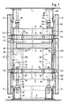
- the exemplary embodiment shown of the cabinet wall is designed as a room divider which extends between the ceiling 1 and floor 3.
- the cabinet wall is delimited on its broad sides by lower skirting boards 5 and upper ceiling boards 6. Between the baseboards 5 and the ceiling strips 6, the cabinet wall is closed by fixed outer walls 7 and movable doors 8.
- a front board 11, see Figure 2 forms the end on each of the narrow end faces.
- a horizontal lower construction floor 13 and a horizontal, upper construction floor 14 form the lower and upper end of the actual department of the cabinet wall, which is divided by vertical side walls 17, which extend from the area of a door 8 towards the opposite outer wall 7.
- the side walls 17 are assigned, as a whole, 19 upper height adjustment devices and, as a whole, 20 lower height adjustment devices, by means of which the side walls 17 are supported on the ceiling 1 or the floor 3.
- Of the majority of the cupboard compartments in the department are present between the lower construction floor 13 and the upper construction floor 14, in the broken-away illustration of FIGS. 1 and 2, essentially only one cabinet compartment with a front door 8 and a rear outer wall 7 can be seen, with a single shelf 21 being shown in FIG extends horizontally between two adjacent side walls 17.
- the shelf is connected to the adjacent side walls 17 on both sides via front shelf supports 23.
- Rear shelf supports 24 form a mounting of the rear edge area of the shelf 21 on the side walls 17. With its rear edge area, the shelf 21 also borders on an inner shelf wall 25.
- the construction floors 13 and 14 and the side walls 17 are particle boards, a special feature being that the particle boards are bordered at least on two opposite edges by profiles made of metal, in the exemplary embodiment by profiles 27 made of aluminum. Further details of the profiles 27 are shown in FIGS. 4 and 5.
- the profile 27 is an extruded hollow profile with a main part 29 which essentially has the shape of a hollow box of rectangular cross section.
- webs 32 extend in the form of projecting ribs which, extending continuously from profile end to profile end and parallel to one another, extend the wall of one of the broad sides of the side Main part 29 form.
- ripple web 33 extends in the form of a continuous rib parallel to the webs 32.
- the end edge area of an associated chipboard can be received in the space between the webs 32, the central corrugated web 33 being hammered into the central area of the chipboard for anchoring the profile 27 and the outer webs 32 preventing the chipboard from splitting by enclosing the edges.
- Longitudinal ribs 34 and 40 projecting into the interior of the main part 29 serve to reinforce the wall and as a system for parts engaging in the cavity of the profile 27, for example a bent holding hook 121 (see FIG. 25) of the shelf support 23.
- a smaller box part 36 is connected via wall parts 37 adjoining the narrow side 35, which are retracted, so that each wall part 37 forms the bottom of a groove 38 that runs from profile end to profile end the end facing away from the narrow side 35 are each delimited by a projecting rib 39.
- Nose-like, bevelled projections 41 adjoin the ribs 39 in the direction facing away from the narrow side 35.
- the design of the profile 27 is the same, regardless of whether it is used as a horizontal profile on the chipboard forming the construction base 13 or 14 or whether it is used as a vertical profile on a vertical chipboard which forms a vertical side wall 17.
- certain punched-outs which are designed in the form of openings and holes in the walls of the main part 29 and the smaller box part 36 of the vertical profile and are explained in more detail below with reference to FIGS. 5 and 43, in the provided on the construction floors 13 and 14 horizontal profiles 27 are omitted.
- the same punchings could also be provided on the horizontal profiles 27 as in the vertically running profiles 27, although some of the punchings in the horizontal profiles 27 are not used in terms of function, as will be explained below.
- FIG. 5 shows the end section of the profile 27 provided as a vertical profile, adjoining the lower profile end 43, that is to say the profile 27 with all the punched-outs provided.
- This is a row of holes 45 formed continuously in the wall of the main part 29 on both broad sides from holes 45 arranged at equal mutual distances, the row of holes of the holes 45 in the end 43 of the profile adjacent area is interrupted by a larger access hole 46.
- the wall part 37 forming the bottom of the groove 38 is broken through on both broad sides of the profile 27 by a row of holes made up of holes 47 arranged at the same distance from one another and by rectangular elongated holes 49 arranged centrally between two adjacent holes 47.
- the elongated holes 49, the holes 45 and the access holes 46 are omitted in the present exemplary embodiment.
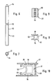
- each of the lower height adjustment devices 20 is a threaded spindle 51 (see FIGS. 6 and 7). This has an approximately centrally arranged recess 52 of reduced diameter and an adjoining, provided with external thread 53 threaded portion which extends continuously to one end. At the end opposite to the external thread 53, the threaded spindle 51 has a square head 54. With its external thread 53, the threaded spindle 51 is screwed into a nut 55, which (see FIGS. 1 and 2) is connected to the upper side of an associated pressure box 57 by welding.
- the pressure boxes 57 are profile sections made of rectangular tube with an upper through opening, to which the welded nut 55 is aligned. With their flat underside, the pressure boxes 57 are supported on panels 59 serving as base strips, which are profile strips made of PVC plastic and, lying on the base 3, extend over the entire length of the cabinet wall.
- the end sections of the threaded spindles facing the side wall to be supported engage in bores which are formed in the particle board forming the relevant side wall.
- the edge regions of the side walls 17 aligned with the threaded spindles 51 can be seen from FIG. 1 is formed by the vertical lateral profiles 27, that is to say that the threaded spindles 51 with their upper section facing away from the external thread 53, more precisely the upper section extending from the recess 52 to the square head 54, extend from the lower profile end 43 (see FIG. 5 ) extend into the cavity of the main part 29 of the profile 27.
- measures are provided to guide this section of the threaded spindle 51 in the relevant profile 27.
- Figures 8 to 10 show a first embodiment, in which this guide is formed from a guide plug 61 made of plastic, which is driven from the free profile end 43 ( Figure 5) into the cavity of the main part 29 of the profile 27 and in the main part 29 the in Figure 10 occupies the position shown.
- the guide plug 61 has a horseshoe-shaped cavity 62 which forms part of a circular cylinder and surrounds the shaft of the threaded spindle 51 with play.
- the guide plug 61 has three groups of resilient holding teeth 63, 64 and 65 which are integrally formed with it and which protrude slightly beyond the largest external dimensions of the plug 61, when the plug 61 is driven into the profile 27 deform and secure the plug 61 in the inserted position.
- the plug 61 driven into the profile 27 is supported on the open edge of the cavity 62 against inwardly projecting ribs 67 of the profile 27, so that the plug 61 does not load the threaded spindle 51 by lateral compressive forces.
- the projecting ribs 67 serve with their bevel as a support and support for the threaded spindle 51 and also have the function of reinforcing the two broad sides of the profile 27.
- a metallic guide body 69 made of die-cast is provided, which is formed in one piece with a side shoe 70.
- the side shoe 7) is broken through by a slot 71 which opens to one side of the side shoe 70.
- the clear width of the slot 71 corresponds to the diameter of the tapered recess 52 of the threaded spindle 51.
- the Ge Windespindel can therefore be inserted with its puncture 52 into the slot 71 from the side.
- the guide body 69 is aligned with the round closed inner end of the slot 71 and, as shown in FIG. 13, has a horseshoe-shaped guide cavity 73, similar to the cavity 62 of the guide plug 61, which has the inserted Surrounds threaded spindle 51 as a guide. If the side shoe 70 rests against the lower profile end 43 of the profile 27, as shown in FIGS. 1 and 2, and the threaded spindle 51 engages with its recess 52 with the slot 71 of the side shoe 70, it fulfills two functions, namely the functions the transmission of compressive forces of the threaded spindle to the profile 27 and the guidance of the threaded spindle 51 through the guide cavity 73 of the guide body 69.
- the side shoe 70 has a retaining pin 74 formed in one piece with it and projecting into the main part 29 of the profile 27.
- This has a collar 75, behind which a blocking body 76 made of elastic plastic material can only be snapped in as shown in FIGS. 11 and 13.
- the blocking body 76 has outer retaining teeth 77 (see FIG. 11). These teeth deform when, when the side shoe 70 is attached to the lower profile end 43 of the profile 27, the locking body 76 is driven into the cavity of the main part 29 of the profile 27.
- FIG. 14 with cross hatching, the position is indicated schematically in a simplified manner, which the locked blocking body 76 occupies in the cavity of the main part 29 of the profile 27.
- the plastic guide plug 61 forms the guide for the threaded spindle 51 in the cavity of the profile 27
- a separate component shown in FIGS. 15 to 17 for transmitting the axial forces of the threaded spindle 51 to the profile 27 it is a side shoe 79 in the form of a bent sheet metal part, the main part of which has the shape of a U-profile section.
- This U-profile section is pushed onto the profile 27 from the lower profile end 43.
- the flat bottom 80 of the U-profile has a bore 81, the diameter of which allows the threaded spindle 51 to be pushed through.
- a slot 82 At the side of the bore 81 there is a slot 82, the inside width of which corresponds to the diameter of the tapered recess 52 of the threaded spindle 51, so that after inserting the recess 52 into the slot 82, the threaded spindle 51 prevents axial movement relative to the bottom 80 of the side shoe 79 is secured.
- the side cheeks 83 of the U-profile lying against the broad sides of the profile 27 have, on the inside, protruding warts 84 which form clamping bodies for securing the side shoe 79 by clamping.
- protruding warts 84 which form clamping bodies for securing the side shoe 79 by clamping.
- approximately centrally arranged holes 85 are aligned with the adjacent holes 45 of the profile 27 when the side shoe 79 is placed on the profile 27, while smaller diameter holes 86 of the side walls 79 are provided for clamping sleeves according to DIN 1481.
- a support bracket 87 is welded to the underside of the bottom 80 so that one leg of the bracket 87, extending in the plane of the front end of the cheeks 83, extends in the direction away from the cheeks 83 .
- the support bracket 87 serves to support plastic profiles which are arranged in the base area of the cabinet wall. Such profiles can be provided to form a privacy or soundproofing and, if necessary, have sealing lips abutting the angle 87.
- the angle 87 can also serve to support plinth panels.
- an angle 89 which corresponds to the function of the support angle 87 and is shown in FIGS. 18 and 19, can be used.
- This angle 89 made of sheet steel is connected to the side shoe 70 made of die-cast zinc not by welding but by a plug connection.
- the angle 89 is driven with its short leg 90 into a slot guide 91 which, as can be seen from FIGS. 11 and 12, is formed on the side shoe 70 below the side edges of the slot 71.
- the short leg 90 of the angle 89 has holding claws 92 formed by expressions, which hold the leg 90 in place after it has been driven into the slot guide 91.
- the threaded spindles 51 of the lower height adjustment devices 20 projecting into the vertical profiles 27 are accessible from the outside at their upper end region via the access holes 46 of the profiles 27.
- the threaded spindles 51 can therefore be rotated in the desired manner relative to the associated nut 55, which is supported on the floor 3 by the associated pressure box 57.
- the vertically measured distance of the threaded spindles 51 from the base 3 can be adjusted.
- the upper adjusting devices 19 have threaded bolts 95 with a smooth shaft instead of threaded spindles 51 provided with the lower adjusting devices 20, that is to say an externally threaded shaft without such a tapered recess as is provided for the threaded spindles 51.
- the threaded bolts 95 have a flat head 96 which is rectangular in outline and is supported against the ceiling 1 via the associated ceiling panel.
- the ceiling panel is the same panel 59 as it also serves as a base panel. Due to its non-circular shape, the head 96 forms a rotation lock for the threaded bolt 95.
- the section of the threaded bolt 95 facing away from the head 96 extends in the same way as is the case with the threaded spindles 51 of the lower adjusting device 20 is, in the cavity of the facing profile end of the associated profile 27.
- a side shoe 70 ' is provided on the facing profile end, which corresponds functionally to the side shoe 70 on the lower height adjustment device 20. The only difference is that in the side shoe 70 'there is no laterally open slot through which the threaded bolt 95 passes, but a smooth through hole is provided for the threaded bolt 95.
- a helical compression spring 97 is provided, which is clamped between a nut 98 seated on the threaded bolt 95 and the side shoe 70 ', so that the axial force generated by the threaded bolt 95 in accordance with the setting of the nut 98 is yielding into the associated one Profile 27 is initiated so that the relevant side wall 17 is resiliently supported with respect to the ceiling 1, whereby any changes in the clear ceiling height that may occur are compensated.
- Figure 1 shows that the side shoe 70 'is provided with a dashed line indicated in it made angle 89.
- a side shoe enclosing the facing profile end corresponding to the side shoe 79 shown in FIGS. 15 to 17, could be used, which has a support bracket 87 welded to it.
- a side shoe on the upper adjuster device 19 would, however, instead of a slot 82 adjacent to the bore 81 in the base 80 (see FIG. 17) have a smooth through hole in the base 80 for the passage of the shaft of the threaded bolt 95.
- the abutting horizontal profiles 27 of the construction floors 13 and 14 and the vertical profiles 27 of the side walls 17 are, as shown in FIG. 2 only for the lower construction floor 13, connected to one another by connecting bolts 99 and 100, which are shown in FIGS. 20 and 21, respectively are shown in more detail.
- the connecting bolts 99 and 100 are driven into the holes 45 of the profile 27 in question, a knurling 101 formed on the shaft of the connecting bolts interlocking with the profile 27 when driven into the hole 45 and securing the bolt in the inserted position.
- the connecting bolt 99 according to FIG. 20 is an end connecting bolt with an end flat head 103 which forms an end stop when it is driven into the profile 27.
- 21 is a double connecting bolt which, instead of a flat head adjoining the knurling 101, has an enlarged collar 105 which serves as an end stop when driving in.
- Both connecting bolts 99 and 100 have a rounded holding head 107 which delimits a tapered end section 106 at the end remote from the knurling 101.
- the connecting bolt 100 provided as a double connecting bolt also has a second holding head 108 corresponding to the holding head 107 at the end adjacent to the collar 105. To mutually clamp the parts, eccentrics, not shown, are turned against the holding heads 107 and 108.
- the strip 111 shown in FIG. 22 is a profile made of hard PVC with sealing lips 112 made of soft PVC projecting on both longitudinal edges and projecting in the same direction. Retaining ribs 113 are formed on the side facing away from the sealing lips 112, engage behind the retaining surfaces on the projections 41 of the profile 27 in the snapped-on state, as indicated in FIG. 22.
- the soft sealing lips 112 are provided for bearing against cabinet doors or fixed wall parts, as shown in FIGS. 1 and 3.
- Undercut longitudinal ribs 115 are formed in the area between the sealing lips 112 of the strip 111, which form a guide for inserting a funnel strip or other decorative strip between them.
- the modified form of a plastic strip 117 shown in FIG. 23, which, like the strip 111 from FIG. 22, can be snapped onto the projections 41 of the profile 27, is a hard PVC strip without sealing lips with a smooth outer surface 118, which as Abutment for the installation of sealing elements (sealing lips) is used, which are attached to the back of facing plates, doors or walls.
- the shelf support 23 shown in FIGS. 24 to 26 has a retaining hook 121 which is bent perpendicularly to its support surface 120 and which is threaded and screwed into a selected hole 45 of the vertical row of holes of the profile 27 on the facing side wall 17 so that it is in the inner cavity of the profile 27 is supported on the longitudinal ribs 34, 40 (FIG. 4).
- the shelf 23 has a raised edge 122 which delimits the support surface 120 at the front end and secures the shelf 21 (see FIG. 1) against slipping forward.
- the shelf 24 shown in FIGS. 27 to 29 differs from the shelf 23 in that it has a shorter retaining hook 124, which can be inserted into a hole 45 in question, and the absence of a raised edge which laterally delimits the support surface 125.
- a bore 126 is provided in the support surface 125 so that the shelf 21 placed thereon can be secured by screwing.
- Such a bore 126 is also present in the support surface 120 of the shelf 23 in order to be able to produce a screw connection to the shelf 21 lying thereon.
- the screwing of the shelf is advantageous in the event of heavy weight loading of the shelf, because in the event of a deflection of the shelf caused by loading, the adjacent side walls 17 are pulled towards one another due to the screwing.
- the elongated holes 49 punched out in the vertical profiles 27 as a vertical row of holes at the base of the grooves 38 serve to position band arms 128 provided as door fittings, one of which is shown in more detail in FIG. 30.
- vertically superimposed projections 129 are formed on the holding arm of the band arm 128, which engage in two adjacent elongated holes 49 of the profile 27 in order to fix the position of the band arm 128.
- projecting bolts 130 are provided which engage in two adjacent holes 45 of the profile 27 (see Figure 1).
- a through hole 131 located between the projections 129 enables the band arm 128 to be screwed on with the aid of a hole 47 of the profile 27 located between adjacent elongated holes 49.
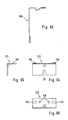
- FIG. 40 shows a modified form of a band arm 127, which differs from the band arm 128 shown in FIG. 30 by a shorter design of its fastening arm provided for contact with the profile 27.
- the positioning bolts 130 of the band arm 128 come with the band arm 127 thereby eliminated.
- no holes 45 in the vertical hole row of the profile 27 are therefore occupied, so that the holes 45 are available for other purposes, for example for hanging in shelf supports 23, 24.
- the band arm 127 is secured to the profile 27 by screwing using a fastening hole 136 on the holding arm, which is aligned with a hole 47 on the profile 27 when the engagement between the projections 132 and associated elongated holes 49 on the profile 27 is established.
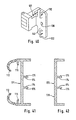
- the row of elongated holes 49 on the vertical profile 27 also serves to fix the position of holders 133 made in the exemplary embodiment from aluminum or die-cast zinc, which have a contact surface and / or a fastening means for external wall parts, for example, form the outer wall 7 shown in FIG. 3.
- holders 133 made in the exemplary embodiment from aluminum or die-cast zinc, which have a contact surface and / or a fastening means for external wall parts, for example, form the outer wall 7 shown in FIG. 3.
- a plurality of holders 133 arranged one above the other are provided.
- Each holder 133 has two vertically superimposed retaining hooks 134 which can be suspended in two superimposed elongated holes 49 of the profile 27.
- the holder 133 forms a flat, outer support surface 135, which is offset relative to the retaining hook 134 in the direction of the outside of the cabinet wall and is provided for supporting the associated outer wall 7.
- An inward raised edge 137 delimiting the support surface 135 forms (see FIG. 3) a support for an inner compartment wall 25 resting thereon.
- Through bores 138 and 139 provided in the support surface 135 enable an associated outer wall to be screwed on.
- an outer wall 7 in question, as shown in FIG. 1 can also be fastened by hanging in, a fitting plate 140 (see FIG. 1) being suspended over the upper edge 141 of the holder 133 in question.
- a screw connection can be provided using the bore 138 and / or 139 as an anti-theft device.
- Figure 1 shows the attachment of the baseboards 5 and the ceiling strips 6 to angle pieces 143, which are made of sheet steel as a stamped and bent part and are shown in Figures 33, 34 and 35.
- a mounting hole 144 is provided on the base or cover strip 5 or 6 serving leg, into which a screw head of the base or cover strip 5 or 6 can be hung.
- the leg having the hole 144 is directed downwards in the skirting board 5 and upwards in the ceiling bar 6.
- a slot 211 (FIG. 64) open to the end edge of the leg can also be provided instead of the closed hole 144.
- the angle piece 143 is attached to the adjacent construction floor 13 or 14, whereby, as can be seen from FIG.
- the leg of the angle piece 143 resting on the profile 27 has rib-like expressions 145 which protrude from the contact surface of the leg and which engage in the groove 38 of the associated profile 27. Holes 146 located between the expressions 145 serve to screw the angle piece 143 to the profile 27.
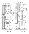
- Figures 36 to 39 show several different ways of designing the base area of the wall unit.
- the example shown in FIG. 36 is similar to the construction of FIG. 1, except that instead of the pressure plate 70 interacting with the height adjustment device 20 in FIG. 1, a side shoe 79 is provided on the profile 27 of the associated side wall 17, the downwardly extending support bracket 87 of which is a system for a lower sealing lip 147 of the skirting 5.
- FIG. 37 provides for a special base panel arrangement instead of the use of a skirting board 5, as shown in FIGS. 1 and 36, the panel 59 provided in the examples described above being provided by a base panel 149 made of hard and soft PVC is replaced, which has a flat, upwardly extending leg 150. This leg 150 is received in a longitudinal slot 151 of an upper diaphragm part 152.
- the panel part 152 made of hard PVC or metal is suspended from holders 153 (FIG. 37), to which it is connected at 154 by a snap connection. These holders are hook-shaped and are shown in detail in FIGS. 59 and 60.
- the holder 153 made of aluminum are similarly secured in the groove 38 of the adjacent profile 27 of the construction floor and attached by screwing, as is also the case with the angle pieces 143 described above, which serve as supports for the skirting board 5.
- the hook-shaped holder 153 can also be screwed with holes 47 in the longitudinal groove 48 of the profile 27.
- FIG. 38 shows a further solution with a skirting board 5, which is fastened to angle pieces 143, but there is no skirting board in the form of a plastic profile, but rather a skirting board 157 bent from a steel sheet.
- the base plate 157 is folded several times, so that an indentation is formed in which a foam strip 160 is held, which is slightly compressed in the indentation and is provided for sound insulation.
- the base plate 157 lies against the base strip 5 under slight pressure without being connected to it.
- FIG. 39 shows a variant in which, as in FIG. 38, the base plate 157 is used, but in addition an upper panel part made of sheet steel overlapping the upper leg 161 is provided.
- This orifice plate 158 is shown in detail in FIG. 63 and is secured to the facing horizontal profile 27 of the construction floor 13 by a snap connection.
- a clamping spring 159 (FIG. 39) is provided, which forms a curved spring strip which is screwed to the underside of the profile 27.
- Figures 61 and 62 show the clamping spring 159 in detail.
- FIGS. 41 and 42 show further exemplary embodiments of plastic strips 171 and 172 which, instead of the plastic strips 111 and 117, as shown in FIGS. 22 and 23, can be snapped onto the projections 41 of the profile 27.
- the engagement with the retaining lugs 41 of the associated profile 27 does not take place by means of external ribs 113 which grip around the retaining lugs 41 from the outside, but rather by means of molded-on retaining webs 174 with an end neck
- the projections 175 extend symmetrically at a relatively short distance from the longitudinal center plane of the plastic strips 171 and 172, so that the retaining projections 175 engage around the lugs 41 of the profile 27 on the mutually facing inner edges, as is the case for the example of a plastic strip 171 in FIG. 43 and for the example of the use of plastic strips 172 can be seen in FIGS. 57 and 58.
- FIG. 43 shows the base area of an exemplary embodiment, which differs from the previously described examples mainly by the use of a height adjustment device 177, which is significantly modified compared to the previously described height adjustment device 20.
- a main part of this height adjustment device 177 is a threaded spindle 179 with an external thread, which is rotatably attached to a pressure plate 180, via the axial forces from the threaded spindle 179 to the floor 3 or, if it is an upper height adjustment device, to the ceiling 1. Details of the threaded spindle 179 and the pressure plate 180 can be found in FIGS. 48 and 49.
- the pressure plate 180 designed as a rectangular metal plate, has a central bore 181 through which an end pin of the threaded spindle 179 is inserted.
- the bore 181 has an extension at the end region facing away from the threaded spindle 179, in which the pin of the threaded spindle is riveted so that the threaded spindle 179 can be rotated relative to the pressure plate 180.
- Figure 50 shows a pressure plate 180 ', which is made narrower than the pressure plate 180 of Figure 49.
- the narrower pressure plate 180 is used when it is a height adjustment device 177 in a corner area of the cabinet wall.
- the threaded spindle 179 has an integrated recess 183 forming inner key surfaces.
- the wrench flats in the recess 183 are provided for the engagement of a suitable ball screwdriver, by means of which the threaded spindle 179 can be rotated for actuating the height adjustment device 177 is.
- elongated access slots 185 are provided when using the height adjustment device 177 instead of the access holes 46 shown in profile 27 in the previously described exemplary embodiments (see FIGS. 43, 57 and 58), which permit the ball screwdriver to be inserted obliquely.
- FIGS. 43 to 46 show a simple solution for a side shoe 187 which can be attached to the profile end of an associated profile 27 and which engages with the external thread of the threaded spindle 179.
- the side shoe 187 is a stamped and bent part made of sheet steel.
- the side shoe 187 has a rectangular flat bottom part 188 which is delimited on two opposite end edges by edge legs 189 and 190 which project vertically from the plane of the bottom part 188.
- An opening is punched out in the central region of the bottom part 188 by means of a conical mandrel. By opening this opening, the opening edges are set in the punching direction.
- An internal thread 191 that matches the external thread of the threaded spindle 179 is cut into the opening that is elongated in this way.
- the side shoe 187 is attached to the profile 27, in which the legs 189 and 190 have been pushed into the interior of the profile 27.
- the leg 189 is narrower than the leg 190.
- the narrower leg 189 as shown in FIG. 47, can be received in the narrower box part 36 of the profile 27, while the wider leg 190 in the one next to the longitudinal ribs 40 located area engages in the main part 29 of the profile 27.
- the leg 190 has a holding projection 193 which is pressed outward and which bears against the inner wall of the profile 27 under prestress.
- the side shoe 187 If the side shoe 187 is attached to the profile end of the profile 27 and the threaded spindle 179 of the height adjustment device 177 is screwed into the internal thread 191 of the side shoe 187, the side shoe 187 transmits 27 axial forces of the threaded spindle 179 to the front face of the profile by contacting its bottom part 188 Profile 27. At the same time, the internal thread 191 forms the guide for the section of the threaded spindle 179 which extends into the cavity of the profile 27.
- the exemplary embodiment according to FIG. 43 differs from the previously explained examples not only in the use of the modified height adjustment device 177 and the consequent formation of an elongated access slot 185 in the profile 27 instead of a round access hole 46, but a further difference exists in the use of the one in FIG 40 shown shorter hinge arm 127 for fastening a door 8 instead of the longer hinge arm 128 shown in FIG. 30.
- the access slot 187 makes it possible to insert a ball head screwdriver at an angle, so that its ball head engages in a hexagon socket at the upper end of the threaded spindle 179, so that you can turn the threaded spindle for height adjustment.
- FIGS. 51 to 53 show a further exemplary embodiment of a side shoe 195 which can be used instead of the side shoe 187.
- This side shoe 195 is quite similar to the side shoe 70 previously described with reference to FIGS. 11 to 13. It is also a die-cast part made of metal, which has a guide body 197 which, in a corresponding manner as is the case with the guide bodies 69 of the side shoe 70, extends from a base plate 196 which is integral with it and which on the end face of the associated one Profile 27 is present. As FIG. 27 shows, the guide body 197 extends in addition to the ribs 67 into the main part of the profile 27.
- the guide body 197 forms a guide which partially encompasses the associated threaded spindle of the associated height adjustment device 177 (see FIG. 54).
- the base plate 196 has a bore which is aligned with the guide body 197 and has an internal thread 198 which is in threaded engagement with the associated threaded spindle 179.
- the side shoe 195 has a holding body 199 which is integral with the base plate 196.
- the holding body 199 extends into the interior of the profile, with locking teeth 201 and 202 formed on the holding body 199 bearing against the inner wall of the profile 27 and the inner longitudinal ribs 40 of the profile 27, around the side shoe 195 in its Secure location.
- the side shoe 195 also has a guide 203 located on the end region of the base plate 196, which is designed in the same way as the guide 91 in the side shoe 70.
- the guide 203 for receiving a support or screen part which can be inserted into it, for example the angle 89 shown in FIGS. 18 and 19.
- a guide 91 of the side shoe 70 or the guide 203 of the guide shoe 195 can also be inserted Angles are inserted, as shown in Figure 57 and designated 205.
- This angle 205 differs from the angle 89 in that its long leg is not bent straight out of the plane of the guide 203, but has an offset 206 (see FIG. 57), so that the leg is offset from the end of the guide 203. It is understood that the leg of the angle 206 which can be received in the guide 203, in a corresponding manner as is the case with the angle 89, has lateral holding claws which secure the inserted angle 205 in the guide 91 or 203. The angle 206 is therefore equally suitable for insertion into the guide 203 of the side shoe 195 and into the guide 91 of the side shoe 70.
- FIGS. 55 and 56 show further details of the base panel 149 and the panel part 152 interacting with it, as are used in the base structures according to FIGS. 37 and 58.
- the panel has protrusions 209 projecting downwards to prevent slipping.
- the distance-free contact of the screen 149 on the floor 3 can be forced by attaching a tool to a shoulder 165, which is formed at the lower end region of leg 150, the base screen 149 into one depressed point of the bottom 3 is pressed, where it remains due to the mutual locking of the ribs 163 and 164.
- a sealing lip 169 made of soft PVC formed near the shoulder 165 now forms a perfect seal on the floor, sound insulation also being achieved.
- molded nubs 209 made of soft PVC form a slip protection for the base panel 149.
Landscapes
- Assembled Shelves (AREA)
- Details Of Audible-Bandwidth Transducers (AREA)
- Drawing Aids And Blackboards (AREA)
- Structure Of Receivers (AREA)
- Building Environments (AREA)
- Finishing Walls (AREA)
Applications Claiming Priority (2)
| Application Number | Priority Date | Filing Date | Title |
|---|---|---|---|
| DE8910709U DE8910709U1 (de) | 1989-09-08 | 1989-09-08 | Zerlegbare Schrankwand mit einem Profil aus Metall und Beschlagteilen |
| DE8910709U | 1989-09-08 |
Publications (3)
| Publication Number | Publication Date |
|---|---|
| EP0416210A2 true EP0416210A2 (fr) | 1991-03-13 |
| EP0416210A3 EP0416210A3 (en) | 1994-10-19 |
| EP0416210B1 EP0416210B1 (fr) | 1997-04-23 |
Family
ID=6842648
Family Applications (1)
| Application Number | Title | Priority Date | Filing Date |
|---|---|---|---|
| EP90109170A Expired - Lifetime EP0416210B1 (fr) | 1989-09-08 | 1990-05-15 | Armoire murale munie d'un profilé métallique et d'éléments de ferrure |
Country Status (5)
| Country | Link |
|---|---|
| EP (1) | EP0416210B1 (fr) |
| AT (1) | ATE151967T1 (fr) |
| DE (2) | DE8910709U1 (fr) |
| DK (1) | DK0416210T3 (fr) |
| ES (1) | ES2100854T3 (fr) |
Cited By (4)
| Publication number | Priority date | Publication date | Assignee | Title |
|---|---|---|---|---|
| RU2183939C2 (ru) * | 2000-05-16 | 2002-06-27 | Головченко Анатолий Иванович | Мебельная стенка |
| ES2262378A1 (es) * | 2004-02-11 | 2006-11-16 | Aida Ingenieria, S.L. | Armario. |
| DE102007044875A1 (de) * | 2007-09-20 | 2009-04-02 | VS Vereinigte Spezialmöbelfabriken GmbH & Co. KG | Plattenförmiges Bauteil |
| DE202009000241U1 (de) * | 2009-01-09 | 2010-05-27 | Hettich-Heinze Gmbh & Co. Kg | Schiene zum Aufhängen von Schränken |
Family Cites Families (14)
| Publication number | Priority date | Publication date | Assignee | Title |
|---|---|---|---|---|
| US2179307A (en) * | 1937-02-24 | 1939-11-07 | Gen Electric | Refrigerator cabinet |
| US3150903A (en) * | 1962-10-22 | 1964-09-29 | Vega Ind Inc | Frame structure for cabinets and the like |
| DE1429611A1 (de) * | 1964-12-31 | 1969-05-29 | Lust Kg Ernst | Schrank |
| GB1089038A (en) * | 1965-06-30 | 1967-11-01 | Ets Dennery Sa Soc | Improvements in or relating to constructional elements particularly for furniture |
| DE1978352U (de) * | 1967-08-23 | 1968-02-08 | Quickfix Productions Proprieta | Fuehrungsprofil fuer schiebetueren von schraenken. |
| ES378111A1 (es) * | 1970-03-31 | 1972-05-16 | Nesofsky Gigante | Mejoras introducidas en los procedimientos de construccion de muebles. |
| CH551170A (de) * | 1972-04-14 | 1974-07-15 | Straessle Marcel | Gestell. |
| DE2829762A1 (de) * | 1978-07-06 | 1980-01-17 | Sandvik Ab | Verfahren und vorrichtung zum abstechen von rohren o.dgl. |
| FR2465113B1 (fr) * | 1979-09-17 | 1986-05-09 | Vattier Claude | Procede de fabrication de meubles a assemblage par profiles tubulaires. meubles et profiles selon le procede |
| DE3028552A1 (de) * | 1980-07-28 | 1982-02-25 | Tegometall Rudolf Bohnacker, 7482 Krauchenwies | Winkelfoermige trageinheit fuer stehende regale |
| GB2116833B (en) * | 1982-01-22 | 1986-02-26 | C O M Coop Operai Metallurg | Modular section for furniture assembly |
| DE8405083U1 (de) * | 1984-02-20 | 1984-05-30 | Christian Holzäpfel GmbH, 7240 Horb | Schrank |
| DE3533895A1 (de) * | 1985-09-23 | 1987-03-26 | Werndl Wilhelm Gmbh & Co Kg | Moebelsockel mit hoehenausgleich |
| DE3804660A1 (de) * | 1988-02-15 | 1989-08-17 | Pan Brasilia Werk Gmbh | Schrank oder schrankwand |
-
1989
- 1989-09-08 DE DE8910709U patent/DE8910709U1/de not_active Expired - Lifetime
-
1990
- 1990-05-15 DK DK90109170.2T patent/DK0416210T3/da active
- 1990-05-15 AT AT90109170T patent/ATE151967T1/de not_active IP Right Cessation
- 1990-05-15 EP EP90109170A patent/EP0416210B1/fr not_active Expired - Lifetime
- 1990-05-15 DE DE59010705T patent/DE59010705D1/de not_active Expired - Fee Related
- 1990-05-15 ES ES90109170T patent/ES2100854T3/es not_active Expired - Lifetime
Cited By (5)
| Publication number | Priority date | Publication date | Assignee | Title |
|---|---|---|---|---|
| RU2183939C2 (ru) * | 2000-05-16 | 2002-06-27 | Головченко Анатолий Иванович | Мебельная стенка |
| ES2262378A1 (es) * | 2004-02-11 | 2006-11-16 | Aida Ingenieria, S.L. | Armario. |
| ES2262378B1 (es) * | 2004-02-11 | 2007-11-01 | Aida Ingenieria, S.L. | Armario. |
| DE102007044875A1 (de) * | 2007-09-20 | 2009-04-02 | VS Vereinigte Spezialmöbelfabriken GmbH & Co. KG | Plattenförmiges Bauteil |
| DE202009000241U1 (de) * | 2009-01-09 | 2010-05-27 | Hettich-Heinze Gmbh & Co. Kg | Schiene zum Aufhängen von Schränken |
Also Published As
| Publication number | Publication date |
|---|---|
| DK0416210T3 (da) | 1997-10-13 |
| DE59010705D1 (de) | 1997-05-28 |
| ATE151967T1 (de) | 1997-05-15 |
| ES2100854T3 (es) | 1997-07-01 |
| EP0416210B1 (fr) | 1997-04-23 |
| DE8910709U1 (de) | 1991-01-17 |
| EP0416210A3 (en) | 1994-10-19 |
Similar Documents
| Publication | Publication Date | Title |
|---|---|---|
| DE69705662T2 (de) | Rollvorrichtung für Schiebetüren, Fenster oder ähnliches | |
| DE10136681A1 (de) | Rahmengestell | |
| DE2735787A1 (de) | Fuehrungselement fuer nachgiebig zu lagernde schiebetuerelemente sowie damit ausgeruestetes schiebetuerelement | |
| EP0104428B1 (fr) | Latte ou plaque de support d'un revêtement de rideau pour un mur ou plafond | |
| AT398516B (de) | Schubkastenauszug | |
| DE202022002815U1 (de) | Verbesserte Inspektionsklappe | |
| EP0329060B1 (fr) | Dispositif porteur pour une couverture de mur ou de plafond | |
| EP3401482B1 (fr) | Meuble avec un dispositif de déplacement d'une partie de meuble | |
| DD250155A5 (de) | Fenster, welches einen rahmen mit einer nut fuer ein inneres plattenfoermiges element enthaelt | |
| EP0416210A2 (fr) | Armoire murale munie d'un profilé métallique et d'éléments de ferrure | |
| EP0736660B1 (fr) | Seuil de porte | |
| DE20019594U1 (de) | Justiervorrichtung eines Rahmens | |
| EP3745919B1 (fr) | Système | |
| DE19808847C2 (de) | Tür- oder Fensterbeschlag | |
| EP1247922B1 (fr) | Support de sol avec une plaque de tête pour supporter une structure de faux plancher surélevé et structure de faux plancher surélevé | |
| DE4013459C2 (de) | Befestigungsvorrichtung für eine Abschlußleiste | |
| DE29508686U1 (de) | Bausatz zum Erstellen von Umkleidekabinen, Trennwänden u.dgl. | |
| EP3299531B1 (fr) | Dalle de plafond de faux-plafond avec élément de verrouillage activable sans outil | |
| EP4474658B1 (fr) | Ensemble d'ancrage mural | |
| DE3232105A1 (de) | Verbindungsvorrichtung fuer eine vorgehaengte wand- oder deckenverkleidung | |
| DE102005032063B3 (de) | Beschlag zur Klemmbefestigung einer Glasscheibe | |
| EP0897043B1 (fr) | Charnière pour portes, fenêtres et similaires | |
| DE19622735A1 (de) | Kupplungsanordnung | |
| DE4021773A1 (de) | Schaltschrank mit einem durch wandelemente und tueren abdeckbaren geruest | |
| EP3256677B1 (fr) | Ferrure destinée à au moins un battant mobile linéairement et meuble |
Legal Events
| Date | Code | Title | Description |
|---|---|---|---|
| PUAI | Public reference made under article 153(3) epc to a published international application that has entered the european phase |
Free format text: ORIGINAL CODE: 0009012 |
|
| AK | Designated contracting states |
Kind code of ref document: A2 Designated state(s): AT BE CH DE DK ES FR GB IT LI LU NL SE |
|
| RHK1 | Main classification (correction) |
Ipc: A47B 47/00 |
|
| PUAL | Search report despatched |
Free format text: ORIGINAL CODE: 0009013 |
|
| AK | Designated contracting states |
Kind code of ref document: A3 Designated state(s): AT BE CH DE DK ES FR GB IT LI LU NL SE |
|
| 17P | Request for examination filed |
Effective date: 19950210 |
|
| 17Q | First examination report despatched |
Effective date: 19950911 |
|
| GRAG | Despatch of communication of intention to grant |
Free format text: ORIGINAL CODE: EPIDOS AGRA |
|
| GRAH | Despatch of communication of intention to grant a patent |
Free format text: ORIGINAL CODE: EPIDOS IGRA |
|
| GRAH | Despatch of communication of intention to grant a patent |
Free format text: ORIGINAL CODE: EPIDOS IGRA |
|
| GRAA | (expected) grant |
Free format text: ORIGINAL CODE: 0009210 |
|
| RAP1 | Party data changed (applicant data changed or rights of an application transferred) |
Owner name: WAIKO BUEROMOEBEL GMBH |
|
| AK | Designated contracting states |
Kind code of ref document: B1 Designated state(s): AT BE CH DE DK ES FR GB IT LI LU NL SE |
|
| REF | Corresponds to: |
Ref document number: 151967 Country of ref document: AT Date of ref document: 19970515 Kind code of ref document: T |
|
| REG | Reference to a national code |
Ref country code: CH Ref legal event code: EP |
|
| REF | Corresponds to: |
Ref document number: 59010705 Country of ref document: DE Date of ref document: 19970528 |
|
| REG | Reference to a national code |
Ref country code: ES Ref legal event code: FG2A Ref document number: 2100854 Country of ref document: ES Kind code of ref document: T3 |
|
| GBT | Gb: translation of ep patent filed (gb section 77(6)(a)/1977) |
Effective date: 19970613 |
|
| REG | Reference to a national code |
Ref country code: CH Ref legal event code: NV Representative=s name: PATENTANWAELTE SCHAAD, BALASS, MENZL & PARTNER AG |
|
| ET | Fr: translation filed | ||
| REG | Reference to a national code |
Ref country code: DK Ref legal event code: T3 |
|
| PLBE | No opposition filed within time limit |
Free format text: ORIGINAL CODE: 0009261 |
|
| STAA | Information on the status of an ep patent application or granted ep patent |
Free format text: STATUS: NO OPPOSITION FILED WITHIN TIME LIMIT |
|
| 26N | No opposition filed | ||
| PGFP | Annual fee paid to national office [announced via postgrant information from national office to epo] |
Ref country code: SE Payment date: 19980515 Year of fee payment: 9 Ref country code: DK Payment date: 19980515 Year of fee payment: 9 |
|
| PGFP | Annual fee paid to national office [announced via postgrant information from national office to epo] |
Ref country code: LU Payment date: 19980522 Year of fee payment: 9 |
|
| PGFP | Annual fee paid to national office [announced via postgrant information from national office to epo] |
Ref country code: ES Payment date: 19980526 Year of fee payment: 9 |
|
| PG25 | Lapsed in a contracting state [announced via postgrant information from national office to epo] |
Ref country code: LU Free format text: LAPSE BECAUSE OF NON-PAYMENT OF DUE FEES Effective date: 19990515 |
|
| PG25 | Lapsed in a contracting state [announced via postgrant information from national office to epo] |
Ref country code: SE Free format text: LAPSE BECAUSE OF NON-PAYMENT OF DUE FEES Effective date: 19990516 |
|
| PG25 | Lapsed in a contracting state [announced via postgrant information from national office to epo] |
Ref country code: ES Free format text: LAPSE BECAUSE OF NON-PAYMENT OF DUE FEES Effective date: 19990517 |
|
| PG25 | Lapsed in a contracting state [announced via postgrant information from national office to epo] |
Ref country code: DK Free format text: LAPSE BECAUSE OF NON-PAYMENT OF DUE FEES Effective date: 19990531 |
|
| EUG | Se: european patent has lapsed |
Ref document number: 90109170.2 |
|
| REG | Reference to a national code |
Ref country code: DK Ref legal event code: EBP |
|
| PGFP | Annual fee paid to national office [announced via postgrant information from national office to epo] |
Ref country code: GB Payment date: 20000510 Year of fee payment: 11 Ref country code: FR Payment date: 20000510 Year of fee payment: 11 |
|
| PGFP | Annual fee paid to national office [announced via postgrant information from national office to epo] |
Ref country code: AT Payment date: 20000511 Year of fee payment: 11 |
|
| PGFP | Annual fee paid to national office [announced via postgrant information from national office to epo] |
Ref country code: CH Payment date: 20000512 Year of fee payment: 11 |
|
| PGFP | Annual fee paid to national office [announced via postgrant information from national office to epo] |
Ref country code: NL Payment date: 20000531 Year of fee payment: 11 |
|
| PGFP | Annual fee paid to national office [announced via postgrant information from national office to epo] |
Ref country code: DE Payment date: 20000616 Year of fee payment: 11 |
|
| PGFP | Annual fee paid to national office [announced via postgrant information from national office to epo] |
Ref country code: BE Payment date: 20000717 Year of fee payment: 11 |
|
| PG25 | Lapsed in a contracting state [announced via postgrant information from national office to epo] |
Ref country code: GB Free format text: LAPSE BECAUSE OF NON-PAYMENT OF DUE FEES Effective date: 20010515 Ref country code: AT Free format text: LAPSE BECAUSE OF NON-PAYMENT OF DUE FEES Effective date: 20010515 |
|
| PG25 | Lapsed in a contracting state [announced via postgrant information from national office to epo] |
Ref country code: BE Free format text: LAPSE BECAUSE OF NON-PAYMENT OF DUE FEES Effective date: 20010531 |
|
| PG25 | Lapsed in a contracting state [announced via postgrant information from national office to epo] |
Ref country code: LI Free format text: LAPSE BECAUSE OF NON-PAYMENT OF DUE FEES Effective date: 20010614 Ref country code: CH Free format text: LAPSE BECAUSE OF NON-PAYMENT OF DUE FEES Effective date: 20010614 |
|
| REG | Reference to a national code |
Ref country code: ES Ref legal event code: FD2A Effective date: 20010503 |
|
| BERE | Be: lapsed |
Owner name: WAIKO BUROMOBEL G.M.B.H. Effective date: 20010531 |
|
| PG25 | Lapsed in a contracting state [announced via postgrant information from national office to epo] |
Ref country code: NL Free format text: LAPSE BECAUSE OF NON-PAYMENT OF DUE FEES Effective date: 20011201 |
|
| GBPC | Gb: european patent ceased through non-payment of renewal fee |
Effective date: 20010515 |
|
| REG | Reference to a national code |
Ref country code: CH Ref legal event code: PL |
|
| PG25 | Lapsed in a contracting state [announced via postgrant information from national office to epo] |
Ref country code: FR Free format text: LAPSE BECAUSE OF NON-PAYMENT OF DUE FEES Effective date: 20020131 |
|
| NLV4 | Nl: lapsed or anulled due to non-payment of the annual fee |
Effective date: 20011201 |
|
| PG25 | Lapsed in a contracting state [announced via postgrant information from national office to epo] |
Ref country code: DE Free format text: LAPSE BECAUSE OF NON-PAYMENT OF DUE FEES Effective date: 20020301 |
|
| PG25 | Lapsed in a contracting state [announced via postgrant information from national office to epo] |
Ref country code: IT Free format text: LAPSE BECAUSE OF NON-PAYMENT OF DUE FEES;WARNING: LAPSES OF ITALIAN PATENTS WITH EFFECTIVE DATE BEFORE 2007 MAY HAVE OCCURRED AT ANY TIME BEFORE 2007. THE CORRECT EFFECTIVE DATE MAY BE DIFFERENT FROM THE ONE RECORDED. Effective date: 20050515 |