EP0416317A2 - Doppelrohrelement - Google Patents
Doppelrohrelement Download PDFInfo
- Publication number
- EP0416317A2 EP0416317A2 EP90115349A EP90115349A EP0416317A2 EP 0416317 A2 EP0416317 A2 EP 0416317A2 EP 90115349 A EP90115349 A EP 90115349A EP 90115349 A EP90115349 A EP 90115349A EP 0416317 A2 EP0416317 A2 EP 0416317A2
- Authority
- EP
- European Patent Office
- Prior art keywords
- double
- tube
- element according
- welded
- connecting ring
- Prior art date
- Legal status (The legal status is an assumption and is not a legal conclusion. Google has not performed a legal analysis and makes no representation as to the accuracy of the status listed.)
- Granted
Links
- 125000006850 spacer group Chemical group 0.000 claims abstract description 16
- 238000003466 welding Methods 0.000 claims description 11
- 238000010276 construction Methods 0.000 claims description 8
- 238000004519 manufacturing process Methods 0.000 claims description 5
- 229920001903 high density polyethylene Polymers 0.000 claims description 4
- 239000012815 thermoplastic material Substances 0.000 claims 1
- 238000010438 heat treatment Methods 0.000 description 3
- 230000008878 coupling Effects 0.000 description 2
- 238000010168 coupling process Methods 0.000 description 2
- 238000005859 coupling reaction Methods 0.000 description 2
- 238000006073 displacement reaction Methods 0.000 description 2
- 238000002347 injection Methods 0.000 description 2
- 239000007924 injection Substances 0.000 description 2
- 238000009434 installation Methods 0.000 description 2
- 239000007788 liquid Substances 0.000 description 2
- 239000000463 material Substances 0.000 description 2
- -1 polyethylene Polymers 0.000 description 2
- 229920001169 thermoplastic Polymers 0.000 description 2
- 239000004416 thermosoftening plastic Substances 0.000 description 2
- 241001136792 Alle Species 0.000 description 1
- 239000002033 PVDF binder Substances 0.000 description 1
- 239000004952 Polyamide Substances 0.000 description 1
- 239000004698 Polyethylene Substances 0.000 description 1
- 239000004743 Polypropylene Substances 0.000 description 1
- 206010041953 Staring Diseases 0.000 description 1
- 230000015572 biosynthetic process Effects 0.000 description 1
- 230000007613 environmental effect Effects 0.000 description 1
- 238000001125 extrusion Methods 0.000 description 1
- 239000012530 fluid Substances 0.000 description 1
- 239000006260 foam Substances 0.000 description 1
- 239000004700 high-density polyethylene Substances 0.000 description 1
- 238000001746 injection moulding Methods 0.000 description 1
- 239000011810 insulating material Substances 0.000 description 1
- 238000000034 method Methods 0.000 description 1
- 230000000149 penetrating effect Effects 0.000 description 1
- 229920002647 polyamide Polymers 0.000 description 1
- 229920000573 polyethylene Polymers 0.000 description 1
- 229920000642 polymer Polymers 0.000 description 1
- 229920001155 polypropylene Polymers 0.000 description 1
- 229920002981 polyvinylidene fluoride Polymers 0.000 description 1
- 238000003825 pressing Methods 0.000 description 1
- 238000000275 quality assurance Methods 0.000 description 1
- 230000008439 repair process Effects 0.000 description 1
- 239000003566 sealing material Substances 0.000 description 1
- 230000003313 weakening effect Effects 0.000 description 1
Images



Classifications
-
- F—MECHANICAL ENGINEERING; LIGHTING; HEATING; WEAPONS; BLASTING
- F16—ENGINEERING ELEMENTS AND UNITS; GENERAL MEASURES FOR PRODUCING AND MAINTAINING EFFECTIVE FUNCTIONING OF MACHINES OR INSTALLATIONS; THERMAL INSULATION IN GENERAL
- F16L—PIPES; JOINTS OR FITTINGS FOR PIPES; SUPPORTS FOR PIPES, CABLES OR PROTECTIVE TUBING; MEANS FOR THERMAL INSULATION IN GENERAL
- F16L9/00—Rigid pipes
- F16L9/12—Rigid pipes of plastics with or without reinforcement
Definitions
- double pipe systems In pipe systems, due to ever increasing requirements regarding safety and environmental protection, double-shell pipe constructions, so-called “double pipe systems", are becoming increasingly important. In such a double pipe, if the inner pipe through which a medium flows fails, the leakage fluid from the outer shell is prevented from escaping.
- German utility model G 88 07 095.6 describes a kit for building a double pipe line system in which the individual parts such as the inner pipe, spacers, outer pipe and fittings are assembled one after the other. Apart from the complex assembly, such a system has the disadvantage that a considerable longitudinal displacement of the inner tube can take place if there is a temperature difference between the inner and outer tube. Special washers, which are fitted into the fittings during assembly, are intended to fix them there if necessary. This makes assembly even more complicated.
- the shape of the spacer rings 3 is not critical as long as the function as a spacer is guaranteed.
- the shape of the centering rings 4 is not critical as long as the function as a stiffening element is ensured. As a rule, they have a rectangular cross section because this is the best way to press them in between the inner and outer tube.
- the connecting rings 5 can also have any conceivable shape, as long as on the one hand a rigid connection between the inner and outer tube and on the other hand good weldability of the individual elements is ensured. Some useful embodiments are shown in FIGS. 1 to 7. The embodiment shown in FIGS. 1 and 2 with an H-shaped cross section is particularly preferred.
- thermoplastics weldable with a heating element can be used as materials.
- materials include polyethylene, polypropylene, polyvinylidene fluoride or polyamides.
- High-density polyethylene (PE-HD) is preferably used. This is a material-homogeneous system, ie all parts connected to one another by welding, and preferably also mechanically applied parts 3 and 4, are made of the same material.
- Fig. 1 shows a straight piece of pipe, which was composed of individual double pipe elements.
- the inner and outer tubes are rigidly connected to one another via the connecting ring, so that no relative movement of the tubes relative to one another is possible. Wall thickness and diameter tolerances are compensated for by the connection ring.
- the connecting ring also represents the connecting element for the butt welding of the heating element of the prefabricated double pipe elements to be carried out on site. Standard welding machines can be used.
- the individual double pipe elements are welded together like monotubes during the construction of the piping system.
- a major advantage of the combination of the connecting ring 5 and the centering ring 4 is also the resulting stiffening of the pipe ends.
- the spacer rings 3 , centering rings 4 and connecting rings 5 are perforated several times in the axial direction, z. B. pierced or grooved, as shown in Fig. 1 to 6.
- the annular gaps between the inner media-carrying pipe and the outer jacket pipe are connected in shots, so that a leakage liquid penetrating from outside or inside can be detected with a leak warning system corresponding to the prior art or discharged via a drain.
- the shape of the holes is not critical.
- the double tube element according to the invention is a rigid system in which the inner tube is rigidly connected to the outer tube in sections. This reliably centers the inner tube. If there are different temperatures between the outer and inner tube, the inner tube cannot slide.
Landscapes
- Engineering & Computer Science (AREA)
- General Engineering & Computer Science (AREA)
- Mechanical Engineering (AREA)
- Rigid Pipes And Flexible Pipes (AREA)
- Flanged Joints, Insulating Joints, And Other Joints (AREA)
- Lining Or Joining Of Plastics Or The Like (AREA)
- External Artificial Organs (AREA)
Abstract
- a) an beiden Enden zwischen das Innenrohr (1) und das Außenrohr (2) je ein Zentrierring (4) angebracht ist;
- b) an die beiden Enden je ein Anschlußring (5) angeschweißt ist, der Innen- und Außenrohr starr miteinander verbindet und
- c) ggf. Abstandsringe (3) als Distanzhalter am Innenrohr angebracht sind.
Description
- Bei Rohrleitungssystemen gewinnen, bedingt durch immer weiter steigende Anforderungen bezüglich Sicherheit und Umweltschutz, zweischalige Rohrkonstruktionen, sogenannte "Doppelrohrsysteme", immer stärker an Bedeutung. Bei einem derartigen Doppelrohr wird bei Versagen des inneren, von einem Medium durchströmten Rohres, die Leckflüssigkeit von der Außenschale am Austreten gehindert.
- Bekannt sind z. B. Rohrsysteme, bei denen der Hohlraum zwischen Innen- und Außenrohr mit einem Polymerschaum oder anderem Dämmaterial verfüllt ist. Dies hat jedoch den Nachteil, daß der Hohlraum nur schwer mit einem Leckwarnsystem überwacht werden kann.
- Bekannte unverfüllte Systeme besitzen eine Reihe von Nachteilen:
- 1. Bei unterschiedlichen Temperaturen von Medium und Außenrohr kommt es zu einem Gleiten des Innenrohres, bedingt durch unterschiedliche thermische Ausdehnungen. Dies macht sich, besonders bei längeren Rohrabschnitten, an Rohrkrümmungen und Verzweigungen störend bemerkbar.
- 2. Die zuverlässige Zentrierung des Innenrohres gestaltet sich insbesondere an Verbindungsstellen äußerst schwierig, was die Systemmontage sowie Reparaturen beträchtlich erschwert.
- So wird beispielsweise im Deutschen Gebrauchsmuster G 88 07 095.6 ein Bausatz zum Aufbau eines Doppelrohr-Leitungssystems beschrieben, bei dem die einzelnen Teile wie Innenrohr, Abstandshalter, Außenrohr und Fittings nacheinander zusammengebaut werden. Abgesehen von der aufwendigen Montage besitzt ein derartiges System den Nachteil, daß beim Vorliegen einer Temperaturdifferenz zwischen Innen- und Außenrohr eine beträchtliche Längsverschiebung des Innenrohrs stattfinden kann. Spezielle Scheiben, die bei der Montage in die Fittings eingepaßt werden, sollen bei Bedarf dort eine Fixierung bewirken. Dies macht die Montage noch komplizierter.
- In der US-PS 4 723 441 werden Doppelrohrabschnitte mit speziellen Fittings formschlüssig verbunden. Dieses System weist hinsichtlich Montage sowie Längsverschiebung des Innenrohrs die gleichen Nachteile wie das zuvor genannte auf.
- Die US-PS 4 779 652 beschreibt Doppelrohrelemente, bei denen Innen- und Außenrohr durch axial angeordnete Rippen getrennt sind. Es wird dort hervorgehoben, daß die beiden Rohre und die Rippen einen einheitlichen Formkörper darstellen. Die dort beschriebenen Doppelrohrelemente können in der benötigten Ausführung jedoch offenbar nur duch Spritzguß hergestellt werden. Dies bedeutet, daß jedes einzelne Element zur Herstellung eine eigene Form benötigt, was der Variabilität des Systems enge Grenzen setzt. Zudem sind Spritzgußformen außerordentlich teuer und daher nur bei Großserien rentabel. Abweichungen von den vorgegebenen Maßen verbieten sich aus diesen Gründen. Daher wäre es wünschenswert, Doppelrohrelemente zur Verfügung zu haben, die aus Extrusionsrohren zusammengesetzt sind.
- Die Doppelrohrelemente der US-PS 4 779 652 stellen ein Modulsystem dar, dessen Endmontage wegen der geringeren Anzahl der Teile wesentlich erleichtert ist. Ein Verbinden der Enden duch Zusammenschweißen ist jedoch nur möglich, wenn das Innenrohr nicht nur exakt zentriert, sondern auch jeder Verzug ausgeschlossen ist. Daher ist es vorteilhaft, wenn beim Verschweißen eine Einspannvorrichtung verwendet wird. Aus diesem Grund und wegen der fehlenden Variabilität kann ein derartiges System in der Praxis nicht befriedigen.
- Schließlich wird in der US-PS 4 786 088 ein Doppelrohrsystem vorgestellt, bei dem in gewissen Abständen Kupplungen angebracht sind, die die Kräfte bei Ausdehnung des Innenrohrs aufnehmen. Jedoch ist die Montage überaus aufwendig, da mangels vorgefertigter Elemente eine Vielzahl von Einzelteilen zusammengebaut werden muß.
- Es stellte sich daher die Aufgabe, ein leicht montierbares System aus einzeln werksseitig herstellbaren Rohrelementen zu entwickeln, deren Enden exakt kreisförmig sind und die sich daher ohne Verwendung einer besonderen Einspannvorrichtung zusammenschweißen lassen. Zudem sollten diese Rohrelemente in ihren Ausmaßen variabel sein, so daß nicht jedes Sondermaß die Anfertigung einer eigenen Spritzgußform erfordert. Selbstverständlich darf dabei keine nennenswerte Dezentrierung des Innenrohrs relativ zum Außenrohr stattfinden.
- Diese Aufgabe wird gelöst durch Doppelrohrelemente aus thermoplastischem Kunststoff, die miteinander verschweißbar sind und dadurch gekennzeichnet sind, daß
- a) an beiden Enden zwischen das Innenrohr 1 und das Außenrohr 2 je ein Zentrierring 4 eingebracht ist;
- b) an die beiden Enden je ein Anschlußring 5 angeschweißt ist, der Innen- und Außenrohr starr miteinander verbindet;
- c) ggf. Abstandsringe 3 als Distanzhalter am Innenrohr angebracht sind.
- Die Form der Abstandsringe 3 ist hierbei unkritisch, solange die Funktion als Distanzhalter gewährleistet ist.
- Genauso ist die Form der Zentrierringe 4 unkritisch, solange die Funktion als Versteifungselement gewährleistet ist. In der Regel besitzen sie einen rechteckigen Querschnitt, weil sie sich in dieser Form am besten zwischen Innen- und Außenrohr einpressen lassen.
- Die Anschlußringe 5 können ebenfalls jede denkbare Form besitzen, solange einerseits eine starre Verbindung zwischen Innen- und Außenrohr und andererseits eine gute Verschweißbarkeit der einzelnen Elemente gewährleistet ist. Einige sinnvolle Ausführungsformen gehen aus den Fig. 1 bis 7 hervor. Besonders bevorzugt ist die in Fig. 1 und 2 gezeigte Ausführungsform mit H-förmigem Querschnitt.
- Als Werkstoffe können hierbei alle mit einem Heizelement schweißbaren Thermoplaste zum Einsatz kommen. Als Beispiele seien Polyethylen, Polypropylen, Polyvinylidenfluorid oder Polyamide genannt. Bevorzugt wird High-density-Polyethylen (PE-HD) verwendet. Es handelt sich hierbei um ein werkstoffhomogenes System, d. h. sämtliche durch Schweißen miteinander verbundenen Teile sowie vorzugsweise auch die mechanisch aufgebrachten Teile 3 und 4 bestehen aus dem gleichen Werkstoff.
- Fig. 1 gibt ein gerades Rohrstück wieder, das aus einzelnen Doppelrohrelementen zusammengesetzt wurde.
- Zur Herstellung von Innen- und Außenrohr werden hierbei nahtlos extrudierte oder gewickelte Rohre in einheitliche Stücke von beispielsweise 5 - 20 m Länge geschnitten.
- Ein erfindungsgemäßes Doppelrohrelement wird auf folgende Weise hergestellt:
- a) Soweit nötig, werden Abstandsringe 3 als Distanzhalter in regelmäßigen Abständen am Innenrohr angebracht. Sie werden vorzugsweise nach bekannten Methoden aufgeschrumpft, wodurch die Bildung von Schweißnähten bzw. eine Schwächung des Innenrohres durch eine Schraubverbindung umgangen wird.
- b) Nun wird das Außenrohr über das Innenrohr gezogen.
- c) Anschließend werden in beide Enden die Zentrierringe 4 so eingebracht, z. B. durch Einpressen, daß eine konzentrische Lage von Innen- und Außenrohr gewährleistet ist.
- d) Daraufhin wird der Anschlußring 5, der mit dem Zentrierring 4 zusammen zentraler und neuartiger Funktionsträger des Systems ist, aufgeschweißt, vorzugsweise durch Heizelement-Stumpfschweissung in Anlehnung an das Merkblatt DVS 2207 des Deutschen Verbandes für Schweißtechnik e.V.. Fig. 2 gibt die Verhältnisse vor dem Zusammenschweißen wieder.
- Über den Anschlußring werden Innen- und Außenrohr starr miteinander verbunden, so daß keine Relativbewegung der Rohre gegeneinander möglich ist. Wanddicken- und Durchmessertoleranzen werden hierbei durch den Anschlußring ausgeglichen.
- Die so hergestellten Doppelrohrelemente sind damit montage- und verlegefertig.
- Der Anschlußring stellt gleichzeitig das Verbindungselement dar für die auf der Baustelle durchzuführende Heizelement-Stumpfschweißung der werkseitig vorgefertigten Doppelrohrelemente. Dabei können handelsübliche Schweißmaschinen eingesetzt werden.
- Die einzelnen Doppelrohrelemente werden hierbei beim Bau des Rohrleitungssystems wie Monorohre miteinander verschweißt.
- Ein wesentlicher Vorteil der Kombination aus Anschlußring 5 und Zentrierring 4 besteht zudem in der dadurch erzielten Versteifung der Rohrschußenden.
- Daher ist immer eine fachgerechte Verschweißung in Anlehnung an DVS 2207 auch bei geringen Wanddicken gewährleistet.
- Bei einer bevorzugten Ausführungsform der vorliegenden Erfindung sind die Abstandsringe 3, Zentrierringe 4 und Anschlußringe 5 in axialer Richtung ggf. mehrmals durchlocht, z. B. durchbohrt oder genutet, wie es auch in Fig. 1 bis 6 wiedergegeben ist. Auf diese Weise stehen die Ringspalte zwischen dem inneren medienführenden Rohr und dem äußeren Mantelrohr schußweise in Verbindung, so daß eine von außen oder innen eindringende Leckflüssigkeit mit einem dem Stand der Technik entsprechenden Leckwarnsystem aufgespürt bzw. über einen Ablaß abgeführt werden kann. Die Form der Löcher ist hierbei unkritisch.
- Folgende Beispiele verdeutlichen, daß das erfindungsgemäße Konstruktionsprinzip des Anschlußringes universell eingesetzt werden kann:
- 1. Mit einer Sonderausführung des Anschlußringes als Vorschweißbund sind lösbare Verbindungen möglich (Beispiel: Flanschverbindung (Fig. 3) oder Verbindung mittels Schnellkupplung).
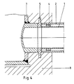
6 ist in dieser Ausführungsform eine Ringnut zur Aufnahme von Dichtungsmaterial. - 2. Bei starren Doppelrohrsystemen ist immer eine Festpunktkonstruktion erforderlich. Bei unterschiedlichen Temperaturen zwischen Innen- und Außenrohr muß die Dehnung des Innenrohres an den Festpunkten in Spannung umgesetzt werden. Fig. 4 zeigt das Ausführungsprinzip für die Anbindung des Doppelrohrsystems an den Festpunkt.
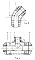
7 ist in diesem Beispiel ein Schacht aus PE-HD-Rohr, 8 eine Betonschale. - 3. Geometrische Variationen des Anschlußringes erlauben die Herstellung von Formteilen wie Bogen (Fig. 5) und T-Stücken (Fig. 6) in zweischaliger Ausführung unter Verwendung der erfindungsgemäßen Zentrier- und Anschlußringe. Bei kurzen Stücken werden keine Abstandsringe benötigt.
- 4. Das Konstruktionsprinzip des Anschlußringes wird auch beim Bau von doppelwandigen Sicherheitsschächten angewendet (Fig. 7). Auf einen zylindrischen doppelwandigen Rohrschuß mit Anschlußringen an den Enden wird ein doppelter Schachtboden angeschweißt. Als Schachtdeckel können alle bekannten Konstruktionen eingesetzt werden.
- Bei dem erfindungsgemäßen Doppelrohrelement handelt es sich um ein starres System, bei dem das Innenrohr schußweise starr mit dem Außenrohr verbunden ist. Damit wird das Innenrohr zuverlässig zentriert. Beim Vorliegen unterschiedlicher Temperaturen zwischen Außen- und Innenrohr ist kein Gleiten des Innenrohres möglich.
- Ein weiterer Vorzug dieser Konstruktion gegenüber beispielsweise dem Rohrsystem der US-PS 4 786 088 liegt darin, daß die Qualitätssicherung wegen der werkseitigen Vormontage besonders einfach ist. Dies ist für den Transport aggressiver bzw. korrosiver Flüssigkeiten ausschlaggebend.
Claims (11)
dadurch gekennzeichnet,
daß es aus PE-HD besteht.
dadurch gekennzeichnet,
daß der Anschlußring (5) einen H-förmigen Querschnitt aufweist.
dadurch gekennzeichnet,
daß die Abstandsringe (3), Zentrierringe (4) und Anschlußringe (5) in axialer Richtung ggf. mehrmals durchlocht sind.
dadurch gekennzeichnet, daß
Priority Applications (1)
| Application Number | Priority Date | Filing Date | Title |
|---|---|---|---|
| AT90115349T ATE89385T1 (de) | 1989-08-31 | 1990-08-10 | Doppelrohrelement. |
Applications Claiming Priority (2)
| Application Number | Priority Date | Filing Date | Title |
|---|---|---|---|
| DE8910408U | 1989-08-31 | ||
| DE8910408U DE8910408U1 (de) | 1989-08-31 | 1989-08-31 | Doppelrohrelement |
Publications (4)
| Publication Number | Publication Date |
|---|---|
| EP0416317A2 true EP0416317A2 (de) | 1991-03-13 |
| EP0416317A3 EP0416317A3 (en) | 1991-10-23 |
| EP0416317B1 EP0416317B1 (de) | 1993-05-12 |
| EP0416317B2 EP0416317B2 (de) | 1998-04-08 |
Family
ID=6842443
Family Applications (1)
| Application Number | Title | Priority Date | Filing Date |
|---|---|---|---|
| EP90115349A Expired - Lifetime EP0416317B2 (de) | 1989-08-31 | 1990-08-10 | Doppelrohrelement |
Country Status (3)
| Country | Link |
|---|---|
| EP (1) | EP0416317B2 (de) |
| AT (1) | ATE89385T1 (de) |
| DE (2) | DE8910408U1 (de) |
Cited By (8)
| Publication number | Priority date | Publication date | Assignee | Title |
|---|---|---|---|---|
| US5820720A (en) * | 1996-05-28 | 1998-10-13 | Campbell; Steve | Method of and apparatus for electrofusion coupling of thermoplastic pipes |
| US6131954A (en) * | 1996-05-28 | 2000-10-17 | Campbell; Steve | Weldable couple for electrofusion coupling of profile wall thermoplastic pipes without a separate coupler |
| US6521072B1 (en) | 1996-05-28 | 2003-02-18 | C&S Intellectual Properties, Llc | Method of coupling profile wall thermoplastic pipes |
| EP1452790A1 (de) * | 2003-02-07 | 2004-09-01 | Alfred Schlemenat | Abdicht- und Verspannelement zum Anschweissen an zwei lösbar zu verbindenden Doppelrohrleitungen |
| WO2012115571A1 (en) * | 2011-02-25 | 2012-08-30 | Kungsörs Plast AB | Fusion welding socket |
| CN107270111A (zh) * | 2017-06-13 | 2017-10-20 | 清华大学 | 一种同心双管结构 |
| CN114251524A (zh) * | 2020-09-22 | 2022-03-29 | 波音公司 | 双壁流体运输系统和相关方法 |
| CN114688352A (zh) * | 2022-04-22 | 2022-07-01 | 中国原子能科学研究院 | 反应堆大厅内用于输送液态金属的管道 |
Families Citing this family (3)
| Publication number | Priority date | Publication date | Assignee | Title |
|---|---|---|---|---|
| DE102005028766B4 (de) * | 2005-06-22 | 2010-04-15 | Airbus Deutschland Gmbh | Rohrleitung sowie Verfahren zur Herstellung der Rohrleitung |
| DE102013107324A1 (de) * | 2013-07-10 | 2015-01-15 | Airbus Operations Gmbh | Leitungssystem für ein Flugzeug und Flugzeug mit einem Leitungssystem |
| DE102013216044A1 (de) * | 2013-08-13 | 2015-02-19 | Bayerische Motoren Werke Aktiengesellschaft | Transportvorrichtung für Flüssigkeiten und/oder Gase |
Family Cites Families (6)
| Publication number | Priority date | Publication date | Assignee | Title |
|---|---|---|---|---|
| DE1870244U (de) * | 1963-01-17 | 1963-04-11 | Linde Eismasch Ag | Kupplungsstueck zur gasdichten loetverbindung der stossstellen ineinander liegender rohre. |
| FR2341094A1 (fr) * | 1976-02-16 | 1977-09-09 | Pichon Michel | Embout a souder pour tuyauteries a double paroi |
| DE2626813C3 (de) * | 1976-06-15 | 1980-10-30 | Bayer Ag, 5090 Leverkusen | Verfahren zur Herstellung lösbarer Verbindungen bei einem mantelbeheizten Rohrleitungssystem |
| DE2744674A1 (de) * | 1977-10-04 | 1979-04-05 | Wilhelm Schulz | Flanschverbindung |
| US4786088A (en) * | 1987-06-25 | 1988-11-22 | Asahi/America, Inc. | Double-containment thermoplastic pipe assembly |
| DE8807095U1 (de) * | 1988-05-31 | 1988-07-21 | Kunststofftechnik KG, 5210 Troisdorf | Bausatz zum Aufbau eines Doppelrohr-Leitungssystems |
-
1989
- 1989-08-31 DE DE8910408U patent/DE8910408U1/de not_active Expired - Lifetime
-
1990
- 1990-08-10 AT AT90115349T patent/ATE89385T1/de active
- 1990-08-10 EP EP90115349A patent/EP0416317B2/de not_active Expired - Lifetime
- 1990-08-10 DE DE9090115349T patent/DE59001430D1/de not_active Expired - Fee Related
Cited By (12)
| Publication number | Priority date | Publication date | Assignee | Title |
|---|---|---|---|---|
| US5820720A (en) * | 1996-05-28 | 1998-10-13 | Campbell; Steve | Method of and apparatus for electrofusion coupling of thermoplastic pipes |
| US5836621A (en) * | 1996-05-28 | 1998-11-17 | Campbell; Steve | Method of and joint for electrofusion coupling of thermoplastic pipes |
| US6131954A (en) * | 1996-05-28 | 2000-10-17 | Campbell; Steve | Weldable couple for electrofusion coupling of profile wall thermoplastic pipes without a separate coupler |
| US6521072B1 (en) | 1996-05-28 | 2003-02-18 | C&S Intellectual Properties, Llc | Method of coupling profile wall thermoplastic pipes |
| EP1452790A1 (de) * | 2003-02-07 | 2004-09-01 | Alfred Schlemenat | Abdicht- und Verspannelement zum Anschweissen an zwei lösbar zu verbindenden Doppelrohrleitungen |
| WO2012115571A1 (en) * | 2011-02-25 | 2012-08-30 | Kungsörs Plast AB | Fusion welding socket |
| US8844598B2 (en) | 2011-02-25 | 2014-09-30 | Kungsors Plast Ab | Fusion welding socket |
| CN107270111A (zh) * | 2017-06-13 | 2017-10-20 | 清华大学 | 一种同心双管结构 |
| CN114251524A (zh) * | 2020-09-22 | 2022-03-29 | 波音公司 | 双壁流体运输系统和相关方法 |
| CN114251524B (zh) * | 2020-09-22 | 2026-01-09 | 波音公司 | 双壁流体运输系统和相关方法 |
| CN114688352A (zh) * | 2022-04-22 | 2022-07-01 | 中国原子能科学研究院 | 反应堆大厅内用于输送液态金属的管道 |
| CN114688352B (zh) * | 2022-04-22 | 2023-09-29 | 中国原子能科学研究院 | 反应堆大厅内用于输送液态金属的管道 |
Also Published As
| Publication number | Publication date |
|---|---|
| EP0416317A3 (en) | 1991-10-23 |
| EP0416317B2 (de) | 1998-04-08 |
| ATE89385T1 (de) | 1993-05-15 |
| EP0416317B1 (de) | 1993-05-12 |
| DE8910408U1 (de) | 1989-11-30 |
| DE59001430D1 (de) | 1993-06-17 |
Similar Documents
| Publication | Publication Date | Title |
|---|---|---|
| DE4129855C2 (de) | Verfahren zum Verschweißen von aus thermoplastischem Kunststoff bestehenden Rohren | |
| EP0416317B1 (de) | Doppelrohrelement | |
| DE3307162A1 (de) | Kunststoffrohrverbindung | |
| CH676689A5 (de) | ||
| EP0426147B1 (de) | Rohr aus Beton mit einer korrosionsfesten Innenauskleidung mit passgerechten Rohrverbindungsstücken und mit den Rohrendbereichen integrierten Abdichtungsanordnungen | |
| EP0314970A1 (de) | Verfahren und Einrichtung zum Auskleiden eines Verbindungs-Endes von Verbund-Rohrleitungskomponenten | |
| EP1108190B1 (de) | Rohr bzw. rohrsystem für rohrleitungsverteiler, heizkreisverteiler, kesselverteiler und dergleichen | |
| DE4328411A1 (de) | Verfahren und Vorrichtung zum Anschließen und Abdichten eines Seitenzulaufs an einen mit einem Inliner aus Kunststoff zu sanierenden Hauptkanal | |
| DE202004020093U1 (de) | Fluidleitungsverbindungsanordnung | |
| EP0306554B1 (de) | Verbindungssystem | |
| DE9107311U1 (de) | Schweißmuffe | |
| EP3298316B1 (de) | Flanschverbindung für bauteile aus kunststoff, insbesondere für rohrförmige bauteile aus kunststoff | |
| DE4139565C2 (de) | Flüssigkeitsdichte Auskleidung von Kanalrohren | |
| DE9100017U1 (de) | Steckverbindung für Rohre aus thermoplastischen Kunststoffen | |
| DE19631082C2 (de) | Verfahren und Vorrichtung zum Sanieren von Abwasserkanälen | |
| EP1927806A1 (de) | Vorrichtung zur Verbindung zweier Rohre | |
| DE69100542T3 (de) | Muffenrohr aus Kunststoff sowie Herstellungsverfahren dafür. | |
| DE102018111207B4 (de) | Abzweigsattel zur Bildung des Abzweigs eines Liningrohres bei der Sanierung eines Abwasserkanals | |
| DE3523014C1 (en) | Electrical welding fitting or welding collar | |
| DE19937851A1 (de) | Rohr bzw. Rohrsystem für Rohrleitungsverteiler, Heizkreisverteiler, Kesselverteiler und dgl. | |
| DE3312682A1 (de) | Anschlussstueck fuer ein ausgekleidetes rohrleitungssystem | |
| AT392149B (de) | Verfahren zum verbinden isolierter leitungsrohre | |
| DE3235146C2 (de) | Anschluß eines flexiblen Schlauches an ein Rohr und Verfahren zur Herstellung eines Anschlußrohrendes für den Anschluß eines Schlauches | |
| DE2757219A1 (de) | Kupplung fuer eine doppelmantelleitung | |
| DE4135433A1 (de) | Doppelwandiger schmutzwasserkanal mit abzweigung |
Legal Events
| Date | Code | Title | Description |
|---|---|---|---|
| PUAI | Public reference made under article 153(3) epc to a published international application that has entered the european phase |
Free format text: ORIGINAL CODE: 0009012 |
|
| 17P | Request for examination filed |
Effective date: 19901215 |
|
| AK | Designated contracting states |
Kind code of ref document: A2 Designated state(s): AT BE CH DE FR GB LI LU NL |
|
| PUAL | Search report despatched |
Free format text: ORIGINAL CODE: 0009013 |
|
| RHK1 | Main classification (correction) |
Ipc: F16L 39/00 |
|
| AK | Designated contracting states |
Kind code of ref document: A3 Designated state(s): AT BE CH DE FR GB LI LU NL |
|
| 17Q | First examination report despatched |
Effective date: 19920819 |
|
| GRAA | (expected) grant |
Free format text: ORIGINAL CODE: 0009210 |
|
| AK | Designated contracting states |
Kind code of ref document: B1 Designated state(s): AT BE CH DE FR GB LI LU NL |
|
| REF | Corresponds to: |
Ref document number: 89385 Country of ref document: AT Date of ref document: 19930515 Kind code of ref document: T |
|
| REF | Corresponds to: |
Ref document number: 59001430 Country of ref document: DE Date of ref document: 19930617 |
|
| GBT | Gb: translation of ep patent filed (gb section 77(6)(a)/1977) |
Effective date: 19930611 |
|
| ET | Fr: translation filed | ||
| EPTA | Lu: last paid annual fee | ||
| PLBI | Opposition filed |
Free format text: ORIGINAL CODE: 0009260 |
|
| 26 | Opposition filed |
Opponent name: AGRU ALOIS GRUBER GES.M.B.H. Effective date: 19940211 Opponent name: SIMONA AG KUNSTSTOFFWERKE Effective date: 19940209 |
|
| NLR1 | Nl: opposition has been filed with the epo |
Opponent name: AGRU ALOIS GRUBER GES.M.B.H. Opponent name: SIMONA AG KUNSTSTOFFWERKE |
|
| APAA | Appeal reference recorded |
Free format text: ORIGINAL CODE: EPIDOS REFN |
|
| APAC | Appeal dossier modified |
Free format text: ORIGINAL CODE: EPIDOS NOAPO |
|
| APAC | Appeal dossier modified |
Free format text: ORIGINAL CODE: EPIDOS NOAPO |
|
| APAC | Appeal dossier modified |
Free format text: ORIGINAL CODE: EPIDOS NOAPO |
|
| PLAW | Interlocutory decision in opposition |
Free format text: ORIGINAL CODE: EPIDOS IDOP |
|
| PUAH | Patent maintained in amended form |
Free format text: ORIGINAL CODE: 0009272 |
|
| STAA | Information on the status of an ep patent application or granted ep patent |
Free format text: STATUS: PATENT MAINTAINED AS AMENDED |
|
| 27A | Patent maintained in amended form |
Effective date: 19980408 |
|
| AK | Designated contracting states |
Kind code of ref document: B2 Designated state(s): AT BE CH DE FR GB LI LU NL |
|
| REG | Reference to a national code |
Ref country code: CH Ref legal event code: AEN Free format text: AUFRECHTERHALTUNG DES PATENTES IN GEAENDERTER FORM |
|
| GBTA | Gb: translation of amended ep patent filed (gb section 77(6)(b)/1977) | ||
| NLR2 | Nl: decision of opposition | ||
| NLR3 | Nl: receipt of modified translations in the netherlands language after an opposition procedure | ||
| ET3 | Fr: translation filed ** decision concerning opposition | ||
| PGFP | Annual fee paid to national office [announced via postgrant information from national office to epo] |
Ref country code: GB Payment date: 20000710 Year of fee payment: 11 |
|
| PGFP | Annual fee paid to national office [announced via postgrant information from national office to epo] |
Ref country code: FR Payment date: 20000718 Year of fee payment: 11 |
|
| PGFP | Annual fee paid to national office [announced via postgrant information from national office to epo] |
Ref country code: NL Payment date: 20000824 Year of fee payment: 11 Ref country code: CH Payment date: 20000824 Year of fee payment: 11 Ref country code: BE Payment date: 20000824 Year of fee payment: 11 Ref country code: AT Payment date: 20000824 Year of fee payment: 11 |
|
| PGFP | Annual fee paid to national office [announced via postgrant information from national office to epo] |
Ref country code: LU Payment date: 20000830 Year of fee payment: 11 |
|
| PGFP | Annual fee paid to national office [announced via postgrant information from national office to epo] |
Ref country code: DE Payment date: 20000906 Year of fee payment: 11 |
|
| PG25 | Lapsed in a contracting state [announced via postgrant information from national office to epo] |
Ref country code: LU Free format text: LAPSE BECAUSE OF NON-PAYMENT OF DUE FEES Effective date: 20010810 Ref country code: GB Free format text: LAPSE BECAUSE OF NON-PAYMENT OF DUE FEES Effective date: 20010810 Ref country code: AT Free format text: LAPSE BECAUSE OF NON-PAYMENT OF DUE FEES Effective date: 20010810 |
|
| PG25 | Lapsed in a contracting state [announced via postgrant information from national office to epo] |
Ref country code: LI Free format text: LAPSE BECAUSE OF NON-PAYMENT OF DUE FEES Effective date: 20010831 Ref country code: CH Free format text: LAPSE BECAUSE OF NON-PAYMENT OF DUE FEES Effective date: 20010831 Ref country code: BE Free format text: LAPSE BECAUSE OF NON-PAYMENT OF DUE FEES Effective date: 20010831 |
|
| BERE | Be: lapsed |
Owner name: KUNSTSTOFFWERK HOHN G.M.B.H. Effective date: 20010831 |
|
| PG25 | Lapsed in a contracting state [announced via postgrant information from national office to epo] |
Ref country code: NL Free format text: LAPSE BECAUSE OF NON-PAYMENT OF DUE FEES Effective date: 20020301 |
|
| GBPC | Gb: european patent ceased through non-payment of renewal fee |
Effective date: 20010810 |
|
| REG | Reference to a national code |
Ref country code: CH Ref legal event code: PL |
|
| PG25 | Lapsed in a contracting state [announced via postgrant information from national office to epo] |
Ref country code: FR Free format text: LAPSE BECAUSE OF NON-PAYMENT OF DUE FEES Effective date: 20020430 |
|
| NLV4 | Nl: lapsed or anulled due to non-payment of the annual fee |
Effective date: 20020301 |
|
| PG25 | Lapsed in a contracting state [announced via postgrant information from national office to epo] |
Ref country code: DE Free format text: LAPSE BECAUSE OF NON-PAYMENT OF DUE FEES Effective date: 20020501 |
|
| REG | Reference to a national code |
Ref country code: FR Ref legal event code: ST |
|
| APAH | Appeal reference modified |
Free format text: ORIGINAL CODE: EPIDOSCREFNO |