EP0416443A2 - Réflecteur de rayon pour deux roues en particulier pour bicyclettes - Google Patents
Réflecteur de rayon pour deux roues en particulier pour bicyclettes Download PDFInfo
- Publication number
- EP0416443A2 EP0416443A2 EP90116458A EP90116458A EP0416443A2 EP 0416443 A2 EP0416443 A2 EP 0416443A2 EP 90116458 A EP90116458 A EP 90116458A EP 90116458 A EP90116458 A EP 90116458A EP 0416443 A2 EP0416443 A2 EP 0416443A2
- Authority
- EP
- European Patent Office
- Prior art keywords
- reflector
- spoke
- reflector element
- angle
- bicycle
- Prior art date
- Legal status (The legal status is an assumption and is not a legal conclusion. Google has not performed a legal analysis and makes no representation as to the accuracy of the status listed.)
- Granted
Links
Images

Classifications
-
- B—PERFORMING OPERATIONS; TRANSPORTING
- B62—LAND VEHICLES FOR TRAVELLING OTHERWISE THAN ON RAILS
- B62J—CYCLE SADDLES OR SEATS; AUXILIARY DEVICES OR ACCESSORIES SPECIALLY ADAPTED TO CYCLES AND NOT OTHERWISE PROVIDED FOR, e.g. ARTICLE CARRIERS OR CYCLE PROTECTORS
- B62J6/00—Arrangement of optical signalling or lighting devices on cycles; Mounting or supporting thereof; Circuits therefor
- B62J6/20—Arrangement of reflectors, e.g. on the wheel spokes ; Lighting devices mounted on wheel spokes
Definitions
- the invention relates to a spoke reflector for two-wheelers, in particular bicycles, with a first reflector element which is fastened to spokes essentially parallel to the spoke plane and has reflector surfaces on both sides, and with a second reflector element arranged at an angle to the first reflector element.
- spoke reflectors For some time now it has been a legal requirement to equip bicycles with spoke reflectors so that the bicycles are more visible even in the dark.
- various types of spoke reflectors are known, the reflector element of which has, for example, the shape of a circle, rectangle or circular ring section and which are equipped with various types of fastening means with which they attach to two adjacent spokes can be brought.
- the reflector element generally consists of a translucent plastic plate with an internal structure such that the plates reflect incident light.
- spoke reflectors commonly found have a reflector element which is arranged essentially parallel to the spoke plane and can therefore reflect light transversely to the spoke plane. This means that in the dark on a side-illuminated bicycle, rotating reflectors become visible to those who are laterally next to the bicycle.
- first hollow-rail-shaped section On the radially outer side in the fastening position there is a first hollow-rail-shaped section on the clamping legs, into which a first reflector element can be inserted essentially parallel to the spoke plane, while on the radially inner side there is a hollow-rail-shaped section which is perpendicular thereto and which receives a second reflector element can, which is arranged perpendicular to the spoke plane and is effective along the longitudinal axis of the bicycle. Accordingly, when a wheel provided with this known spoke reflector is illuminated by a vehicle approaching from the rear (or front), the reflector element arranged perpendicular to the spoke plane reflects light in this direction.
- the well-known spoke reflector increases the safety of the bicycle in road traffic only insufficient.
- Bicycles are usually provided with mudguards which cover the largest area of a reflector element arranged perpendicular to the spoke plane, the possible lateral overhang being limited by the bicycle frame, which allows only a small lateral clearance.
- the reflector elements arranged perpendicular to the spoke plane the radial dimensions approximately coincides with those of the other reflector element lying in the spoke plane, has only a small effective reflector surface, which reflect light that is difficult to see, especially in poor visibility conditions such as fog or rain.
- the known reflector at best shows the existence of the bicycle as long as the driver is in the extension of the longitudinal axis of the bicycle . This is the case, for example, on a straight route and when there is a greater distance between the two vehicles.
- the closer the motor vehicle approaches the bicycle the more the motorist, who is usually further to the middle of the road than a cyclist, gets out of the longitudinal axis of the bicycle, so that he has some time before the overtaking process, in which there is then a risk of collision, device from the reflection area of the known spoke reflector.
- This also applies, for example, to situations in which the cyclist enters a road curve or drives a "diverter" in the direction of the roadway means, which is particularly dangerous.
- the present invention is therefore based on the object of further developing a spoke reflector of the type under consideration so that it offers increased safety for bicycles (and other two-wheeled vehicles), in particular in traffic situations in which the bicycle is overhauled in poor visibility conditions.
- the spoke reflector according to the invention has at least one obliquely rearward-facing reflector surface, which becomes effective when a driver has approached the bicycle on a straight path or when both vehicles move at an angle to one another, for example when cornering.
- the driver of the following motor vehicle before the overtaking process, comes into a reflection area which indicates the existence and position of the bicycle to be overtaken, as a result of which its safety can be significantly increased.
- the invention accordingly provides that at least one reflector surface of the second reflector element forms an angle with the adjacent reflector surface of the first reflector element that is greater than 90 °, preferably 100 ° to 160 °. This also ensures that the effective surface of the second reflector element is not covered by a possible fender of the wheel if the orientation of the reflector surface is such that it points past the edge of the fender.
- the second reflector element also extend over a greater length than the first reflector element, thereby creating an enlarged effective reflection surface which appears as an elongated, wandering light band.
- the second reflector element preferably projects equally far beyond the first reflector element on both sides.
- the second reflector element is plate-shaped and has two opposite reflector surfaces, as is preferred, the other reflector surface encloses an angle with the assigned reflector surface of the first reflector element that is less than 90 °, as a result of which incident light is emitted onto the reflector surface of the first reflector element becomes what increases the side visibility.
- the second reflector element with its central axis is white arranged substantially at right angles to the first reflector element, this design being particularly easy to meet.
- one or both reflector sides of the second reflector element are polygonal in plan view, in that preferably two reflector surface sections running at an angle to one another are provided, such that the surface section adjoining the reflector surface of the first reflector element has the angle greater than 90 therein ° includes.
- This surface section achieves the effect described above with regard to avoiding a "dead area" behind the bicycle and ensures that the driver of an overtaking motor vehicle enters the associated reflection area before the overtaking process, while the other surface section, preferably arranged at right angles to the spoke plane second reflector element protrudes substantially beyond a possibly existing fender and points directly in the direction of the longitudinal axis of the bicycle, so that subsequent motor vehicles are already shown the existence of a bicycle at a relatively great distance.
- a bicycle equipped with the reflector according to the invention is thus clearly visible both for a motor vehicle approaching approximately in the extension of the longitudinal axis of the bicycle and for a motor vehicle that is offset laterally, as a result of which its safety is considerably increased.
- the reflective effect of the reflector according to the invention can also be increased by the fact that the second reflector element 3 or more extends at an angle to one another Has reflection surface sections.
- the respectively adjacent reflection surface sections preferably enclose the same angle between them.
- the conical widening of the cross-section of the second reflector element in the area of the connection surface with the first reflector element also increases the stability of the spoke reflector according to the invention, since the increased footprint and cross-sectional dimensions of the second reflector element in the fastening region ensure considerably increased strength.
- the second reflector element can be attached to the first reflector element in such a way that the contact or connecting surface of the two reflector elements in the installed position runs essentially along the radial of the spoke wheel.
- the reflector surfaces of the reflector element in the top and bottom position on the wheel point forwards and backwards in the horizontal direction.
- This vertical arrangement of the reflector surfaces of the second Re By means of its arrangement, the reflector element can be positioned in a predetermined manner at an angle to the radial of the spoked wheel, a right angle to the radial being preferred, since the reflector surfaces point frontally to the front and to the rear at half the height of their revolution.
- the two reflector elements can be attached to one another by an adhesive connection, which is particularly easy to produce.
- the two reflector elements can also be produced in one piece, for example by a casting or pressing process.
- the second reflector element can be provided with a fastening means, for example in the form of a clip, with which it can be fastened to the first reflector element.
- a fastening means for example in the form of a clip, with which it can be fastened to the first reflector element.
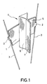
- the figures show three different embodiments of the spoke reflector according to the invention in a largely schematic manner.
- the spoke reflector according to FIG. 1 contains a first reflector element 1, which has the shape of a circular ring section and is fastened to two adjacent spokes 3 parallel to the spoke plane by means of a clamping device 2, which is only indicated.
- a second reflector element 4 is fastened to the first reflector element 1, for example by means of an adhesive connection, and divides the reflector surface 5 of the first reflector element 1 into two equally large, mirror-symmetrical surface sections.
- the connecting surface between the two reflector elements 1, 4 is essentially on the radial of the spoke wheel, but it is emphasized that the longitudinal axis of the connecting surface can run at an angle, preferably at a right angle to the radial, in which case the reflector surface of the reflector element 4 assumes the effective reflection position elsewhere in the course of its circular motion.
- the reflector element 4 projects beyond the reflector element 1 on both sides in order to enlarge the reflector surface. This measure contributes to the fact that, from the perspective of an observer in front of or behind the bicycle, the reflector surface of the reflector element 4 not only flashes briefly, but appears as an elongated light band.
- the width of the reflector element 4 is predetermined by the distance from the bicycle frame or the struts fastening the mudguards.
- the spoke reflector is attached to the wheel in such a way that the reflector element 4 points to the left from the perspective of a person sitting on the bicycle.
- the inner surface of the reflector elements is designed in such a way that it has reflective properties, whereby it is designed in a faceted manner so that it emits differently directed light beams. If, for example, a bicycle equipped with the spoke reflector according to the invention approaches a motor vehicle from behind and illuminates the spoke reflector in the dark with obliquely incident light, part of the light emitted again by the reflector elements 1 and 4 falls on the reflector surface of the other reflector element, causing the light intensity the reflection from the reflector surfaces is increased. As a result, the visibility of the spoke reflector is improved even in the event of poor light and / or poor visibility, so that the risk of an accident for a cyclist is reduced.
- the reflector element 4 has two surface sections arranged on both sides at an angle, the section 6 adjoining the reflector element 1 at an angle ⁇ 2 equal to approximately 115 ° to the reflector surface of the reflector element 1, while the surface section 7 in 90 ° angle is arranged.
- ⁇ 2 equal to approximately 115 ° to the reflector surface of the reflector element 1
- ⁇ 7 in 90 ° angle is arranged.
- the second reflector element 8 has only one reflector surface 9, which encloses an angle ⁇ 2 equal to approximately 100 ° with the reflector surface of the reflector element 1, so that (viewed in the direction of travel) obliquely incident light from behind is reflected towards the middle of the street.
- This design has the advantage that practically no light (or very little light) is reflected in an area that is usually covered from the rear by a mudguard attached to the wheel.
- FIG. 4 shows an embodiment in which the second reflector element 10 has three reflector surfaces 11, 12, 13 on each reflector side, each surface including the same angle with the adjacent surface.
- the reflector surfaces can also be formed on only one side.
Landscapes
- Engineering & Computer Science (AREA)
- Mechanical Engineering (AREA)
- Lighting Device Outwards From Vehicle And Optical Signal (AREA)
- Optical Elements Other Than Lenses (AREA)
- Illuminated Signs And Luminous Advertising (AREA)
Applications Claiming Priority (2)
| Application Number | Priority Date | Filing Date | Title |
|---|---|---|---|
| DE3929799 | 1989-09-07 | ||
| DE3929799A DE3929799A1 (de) | 1989-09-07 | 1989-09-07 | Speichenreflektor fuer zweiraeder, insbesondere fahrraeder |
Publications (3)
| Publication Number | Publication Date |
|---|---|
| EP0416443A2 true EP0416443A2 (fr) | 1991-03-13 |
| EP0416443A3 EP0416443A3 (en) | 1992-03-25 |
| EP0416443B1 EP0416443B1 (fr) | 1994-11-30 |
Family
ID=6388859
Family Applications (1)
| Application Number | Title | Priority Date | Filing Date |
|---|---|---|---|
| EP90116458A Expired - Lifetime EP0416443B1 (fr) | 1989-09-07 | 1990-08-28 | Réflecteur de rayon pour deux roues en particulier pour bicyclettes |
Country Status (3)
| Country | Link |
|---|---|
| EP (1) | EP0416443B1 (fr) |
| AT (1) | ATE114565T1 (fr) |
| DE (2) | DE3929799A1 (fr) |
Cited By (5)
| Publication number | Priority date | Publication date | Assignee | Title |
|---|---|---|---|---|
| WO1996009202A1 (fr) * | 1994-09-19 | 1996-03-28 | Scot Burison | Dispositif de securite monte sur une bicyclette et reflechissant la lumiere |
| WO2003099644A1 (fr) * | 2002-05-23 | 2003-12-04 | Vincent Cecil Thompson | Dispositif d'alerte |
| USD576903S1 (en) | 2006-11-24 | 2008-09-16 | Vincent Cecil Thompson | Reflector for attachment to a wheel of a bicycle |
| EP2705999A1 (fr) * | 2012-09-07 | 2014-03-12 | Illinois Tool Works, Inc. | Réflecteur composite |
| WO2014208515A1 (fr) * | 2013-06-25 | 2014-12-31 | 岡崎産業株式会社 | Élément réflecteur pour vélo |
Families Citing this family (1)
| Publication number | Priority date | Publication date | Assignee | Title |
|---|---|---|---|---|
| DE9404532U1 (de) * | 1994-03-17 | 1994-05-19 | Eberhard J. Kleemann, Repräsentanz Bayern Deutsche Centralbodenkredit-AG, 81925 München | Reflektorwindrad für Fahrräder |
Family Cites Families (7)
| Publication number | Priority date | Publication date | Assignee | Title |
|---|---|---|---|---|
| US3951517A (en) * | 1974-12-09 | 1976-04-20 | Levy Leon M | Wide angled reflector unit for spoked wheel |
| US3924928A (en) * | 1975-03-12 | 1975-12-09 | Robert C Trimble | Attachment for reflectors for spoke wheels |
| US4178070A (en) * | 1976-06-25 | 1979-12-11 | Thibodeau Robert W Sr | Bicycle safety device |
| FR2525551A1 (fr) * | 1982-04-26 | 1983-10-28 | Patois Raymond | Dispositif de signalisation nocturne pour roues de vehicules a deux roues, par surfaces retro-reflechissantes a double orientation |
| DE3406769A1 (de) * | 1984-02-24 | 1985-11-21 | Franz Dipl.-Ing. Pfordte (FH), 8000 München | Rueckstrahler zur befestigung an fahrradspeichen |
| DE3420534A1 (de) * | 1984-06-01 | 1985-12-05 | Wilbert, Bruno, 5413 Bendorf | Speichenreflektor fuer zweiraeder, insbesondere fahrraeder |
| DE8703402U1 (de) * | 1987-03-06 | 1987-06-25 | Ferstl, Rolf, 7323 Hattenhofen | Speichenreflektor für Zweiradfahrzeuge, vorzugsweise für Fahrräder |
-
1989
- 1989-09-07 DE DE3929799A patent/DE3929799A1/de active Granted
-
1990
- 1990-08-28 EP EP90116458A patent/EP0416443B1/fr not_active Expired - Lifetime
- 1990-08-28 AT AT90116458T patent/ATE114565T1/de not_active IP Right Cessation
- 1990-08-28 DE DE59007832T patent/DE59007832D1/de not_active Expired - Fee Related
Cited By (6)
| Publication number | Priority date | Publication date | Assignee | Title |
|---|---|---|---|---|
| WO1996009202A1 (fr) * | 1994-09-19 | 1996-03-28 | Scot Burison | Dispositif de securite monte sur une bicyclette et reflechissant la lumiere |
| WO2003099644A1 (fr) * | 2002-05-23 | 2003-12-04 | Vincent Cecil Thompson | Dispositif d'alerte |
| USD576903S1 (en) | 2006-11-24 | 2008-09-16 | Vincent Cecil Thompson | Reflector for attachment to a wheel of a bicycle |
| EP2705999A1 (fr) * | 2012-09-07 | 2014-03-12 | Illinois Tool Works, Inc. | Réflecteur composite |
| WO2014208515A1 (fr) * | 2013-06-25 | 2014-12-31 | 岡崎産業株式会社 | Élément réflecteur pour vélo |
| JPWO2014208515A1 (ja) * | 2013-06-25 | 2017-02-23 | 岡崎産業株式会社 | 自転車用反射器材 |
Also Published As
| Publication number | Publication date |
|---|---|
| DE59007832D1 (de) | 1995-01-12 |
| EP0416443B1 (fr) | 1994-11-30 |
| DE3929799C2 (fr) | 1992-12-03 |
| DE3929799A1 (de) | 1991-03-21 |
| ATE114565T1 (de) | 1994-12-15 |
| EP0416443A3 (en) | 1992-03-25 |
Similar Documents
| Publication | Publication Date | Title |
|---|---|---|
| EP0997346A1 (fr) | Rétroviseur extérieur pour véhicules, en particulier véhicules à moteur | |
| EP0416443B1 (fr) | Réflecteur de rayon pour deux roues en particulier pour bicyclettes | |
| DE3905779C2 (fr) | ||
| DE102006008279B4 (de) | Fahrzeugerkennungsvorrichtung | |
| DE2755432A1 (de) | Leuchte mit einem hohlspiegelreflektor, insbesondere rueck-, sicherungs- oder signalleuchte oder scheinwerfer | |
| DE499702C (de) | Beleuchtungsanlage zum Kenntlichmachen der Umrisse von Fahrzeugen, insbesondere Kraftfahrzeugen | |
| DE2628243C2 (fr) | ||
| DE3038222A1 (de) | Leuchte mit einem hohlspiegelreflektor, insbesondererueck-, sicherungs- oder signalleuchte oder scheinwerfer | |
| DE8703402U1 (de) | Speichenreflektor für Zweiradfahrzeuge, vorzugsweise für Fahrräder | |
| DE10333502A1 (de) | Fahrzeug mit Frontbremsleuchte | |
| DE102021131816B3 (de) | Zusatzleuchtvorrichtung für ein Zweirad und Zweirad damit | |
| DE102023129450B4 (de) | Positionslicht für ein Fahrzeug | |
| DE19800478A1 (de) | Reflektierender Sicherheits-Reifen | |
| DE2622275A1 (de) | Sicherheitsabstand-anzeiger fuer zwei- und dreiraeder (sicherheitszubehoer) | |
| DE3041693C2 (fr) | ||
| DE112024001560T5 (de) | Sattelfahrzeug | |
| DE2647889C2 (de) | Signalleuchte, insbesondere Rück- oder Sicherungsleuchte | |
| DE19631067C1 (de) | Blinklicht erzeugende Warnleuchte, insbesondere Rundum-Kennleuchte | |
| DE202019005267U1 (de) | Fahrradreifen mit farblichen Einfügungen in der Lauffläche | |
| DE8416410U1 (de) | Sicherheitsstrahler für Fahrräder | |
| DE2420735C3 (de) | Rückstrahlersystem für Radfahrzeuge, insbesondere für Fahrräder | |
| DE102022129888A1 (de) | Pedal für ein Velomobil, optisches System und ein von einem Menschen angetriebenes Fahrzeug | |
| DE20122377U1 (de) | Fahrzeug mit einer zusätzlichen Bremsleuchte | |
| DE202023101661U1 (de) | Fahrrad mit einem Schutzblech und/oder eine Radgabel | |
| CH693230A5 (de) | Strahlkörper für Räder mitSpeichen. |
Legal Events
| Date | Code | Title | Description |
|---|---|---|---|
| PUAI | Public reference made under article 153(3) epc to a published international application that has entered the european phase |
Free format text: ORIGINAL CODE: 0009012 |
|
| AK | Designated contracting states |
Kind code of ref document: A2 Designated state(s): AT CH DE FR LI NL |
|
| PUAL | Search report despatched |
Free format text: ORIGINAL CODE: 0009013 |
|
| AK | Designated contracting states |
Kind code of ref document: A3 Designated state(s): AT CH DE FR LI NL |
|
| 17P | Request for examination filed |
Effective date: 19920924 |
|
| 17Q | First examination report despatched |
Effective date: 19931001 |
|
| GRAA | (expected) grant |
Free format text: ORIGINAL CODE: 0009210 |
|
| AK | Designated contracting states |
Kind code of ref document: B1 Designated state(s): AT CH DE FR LI NL |
|
| REF | Corresponds to: |
Ref document number: 114565 Country of ref document: AT Date of ref document: 19941215 Kind code of ref document: T |
|
| REF | Corresponds to: |
Ref document number: 59007832 Country of ref document: DE Date of ref document: 19950112 |
|
| ET | Fr: translation filed | ||
| PLBE | No opposition filed within time limit |
Free format text: ORIGINAL CODE: 0009261 |
|
| STAA | Information on the status of an ep patent application or granted ep patent |
Free format text: STATUS: NO OPPOSITION FILED WITHIN TIME LIMIT |
|
| 26N | No opposition filed | ||
| PGFP | Annual fee paid to national office [announced via postgrant information from national office to epo] |
Ref country code: FR Payment date: 19970826 Year of fee payment: 8 |
|
| PGFP | Annual fee paid to national office [announced via postgrant information from national office to epo] |
Ref country code: AT Payment date: 19970827 Year of fee payment: 8 |
|
| PGFP | Annual fee paid to national office [announced via postgrant information from national office to epo] |
Ref country code: NL Payment date: 19970831 Year of fee payment: 8 |
|
| PGFP | Annual fee paid to national office [announced via postgrant information from national office to epo] |
Ref country code: CH Payment date: 19971112 Year of fee payment: 8 |
|
| PG25 | Lapsed in a contracting state [announced via postgrant information from national office to epo] |
Ref country code: AT Free format text: LAPSE BECAUSE OF NON-PAYMENT OF DUE FEES Effective date: 19980828 |
|
| PG25 | Lapsed in a contracting state [announced via postgrant information from national office to epo] |
Ref country code: LI Free format text: LAPSE BECAUSE OF NON-PAYMENT OF DUE FEES Effective date: 19980831 Ref country code: CH Free format text: LAPSE BECAUSE OF NON-PAYMENT OF DUE FEES Effective date: 19980831 |
|
| PG25 | Lapsed in a contracting state [announced via postgrant information from national office to epo] |
Ref country code: NL Free format text: LAPSE BECAUSE OF NON-PAYMENT OF DUE FEES Effective date: 19990301 |
|
| REG | Reference to a national code |
Ref country code: CH Ref legal event code: PL |
|
| PG25 | Lapsed in a contracting state [announced via postgrant information from national office to epo] |
Ref country code: FR Free format text: LAPSE BECAUSE OF NON-PAYMENT OF DUE FEES Effective date: 19990430 |
|
| NLV4 | Nl: lapsed or anulled due to non-payment of the annual fee |
Effective date: 19990301 |
|
| REG | Reference to a national code |
Ref country code: FR Ref legal event code: ST |
|
| PGFP | Annual fee paid to national office [announced via postgrant information from national office to epo] |
Ref country code: DE Payment date: 20020430 Year of fee payment: 12 |
|
| PG25 | Lapsed in a contracting state [announced via postgrant information from national office to epo] |
Ref country code: DE Free format text: LAPSE BECAUSE OF NON-PAYMENT OF DUE FEES Effective date: 20030301 |