EP0416519A2 - Silberhalogenid enthaltendes fotografisches lichtempfindliches Material und lichtempfindliches fotografisches Material identifizierender Kodedrucker - Google Patents
Silberhalogenid enthaltendes fotografisches lichtempfindliches Material und lichtempfindliches fotografisches Material identifizierender Kodedrucker Download PDFInfo
- Publication number
- EP0416519A2 EP0416519A2 EP90116932A EP90116932A EP0416519A2 EP 0416519 A2 EP0416519 A2 EP 0416519A2 EP 90116932 A EP90116932 A EP 90116932A EP 90116932 A EP90116932 A EP 90116932A EP 0416519 A2 EP0416519 A2 EP 0416519A2
- Authority
- EP
- European Patent Office
- Prior art keywords
- sensitive material
- silver halide
- photographic light
- halide photographic
- film
- Prior art date
- Legal status (The legal status is an assumption and is not a legal conclusion. Google has not performed a legal analysis and makes no representation as to the accuracy of the status listed.)
- Withdrawn
Links
Images





Classifications
-
- G—PHYSICS
- G03—PHOTOGRAPHY; CINEMATOGRAPHY; ANALOGOUS TECHNIQUES USING WAVES OTHER THAN OPTICAL WAVES; ELECTROGRAPHY; HOLOGRAPHY
- G03C—PHOTOSENSITIVE MATERIALS FOR PHOTOGRAPHIC PURPOSES; PHOTOGRAPHIC PROCESSES, e.g. CINE, X-RAY, COLOUR, STEREO-PHOTOGRAPHIC PROCESSES; AUXILIARY PROCESSES IN PHOTOGRAPHY
- G03C11/00—Auxiliary processes in photography
- G03C11/02—Marking or applying text
-
- G—PHYSICS
- G03—PHOTOGRAPHY; CINEMATOGRAPHY; ANALOGOUS TECHNIQUES USING WAVES OTHER THAN OPTICAL WAVES; ELECTROGRAPHY; HOLOGRAPHY
- G03B—APPARATUS OR ARRANGEMENTS FOR TAKING PHOTOGRAPHS OR FOR PROJECTING OR VIEWING THEM; APPARATUS OR ARRANGEMENTS EMPLOYING ANALOGOUS TECHNIQUES USING WAVES OTHER THAN OPTICAL WAVES; ACCESSORIES THEREFOR
- G03B27/00—Photographic printing apparatus
- G03B27/32—Projection printing apparatus, e.g. enlarger, copying camera
- G03B27/52—Details
- G03B27/521—Arrangements for applying a supplementary information onto the sensitive material, e.g. coding
Definitions
- the present invention relates to an apparatus for printing bar codes for identifying the product kind (including the product name, maker name, etc.) and frame numbers on a silver halide photographic light-sensitive material (hereinafter may be called a photographic material or a film for simplicity) as latent images.
- a silver halide photographic light-sensitive material hereinafter may be called a photographic material or a film for simplicity
- the product kind and each frame number are printed on the outer edges in the outside area of each frame in the longitudinal direction of the film as a latent image.
- each frame of the developed film is provided with its number as a developed image
- the image of a desired frame can be printed by specifying the corresponding frame number.
- the orderer and the order receiver need not read the frame number by comparing with the negative film, resulting in easy handling. Therefore, there are increasing requests for recording the frame number on each print.
- patterned information such as a bar code is printed on a photographic material beforehand and when the printer reads the information during hard copy, the corresponding frame number (numeral) is printed on the back of a hard copy. It is useful to print a code on the outer edge of a photographic material instead of the picture plane.
- a side notch 101 shown in Fig. 1 is generally formed on the outer edge on one side of each frame of the developed photographic material.
- the side notch 101 is used to set each frame of a developed photographic material at the correct location of the printer for generating hard copy. At present, such a side notch 101 is formed on one outer edge of a photographic material, and the selected side varies with each print system.
- the side notch 101 is formed in the frame identification frame number code area instead of the product kind identification code (which is common to all the frames) area, a part of the frame number code is cut off, causing the printer to misread frame numbers.
- the frame number bar codes are printed on the outer edges on both sides of a photographic material instead of one side.
- the DX code is printed on one outer edge as a product kind code representing the maker and product names, and each frame number bar code cannot be printed independently on the side where the DX code is printed. Therefore, it is necessary that each frame number bar code is combined with the DX code and a composite bar code representing the product kind and the frame number is printed.
- the manufacturer requires 1280 types of negative or positive and spare films, resulting in an increase in the negative or positive film production cost, complicated management, and a troublesome switching operation.
- the printing method is a dot image generation method
- the storage of 1280 types of data requires a large memory capacity, resulting in a complicated apparatus and an increase in cost.
- the object of the present invention is to provide a printer which facilitates bar code production, maintenance, and management, minimizes the storage capacity, and reduces the apparatus cost by solving those problems.
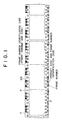
- Fig. 1 shows a schematic view of identification codes and frame numbers which are printed on a silver halide photographic light-sensitive material F (hereinafter may be called a photographic material or a film for simplicity), which is an embodiment of the present invention, during manufacture
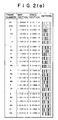
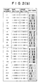
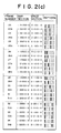
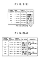
- Figs. 2(a), (b), (c), (d), and (e) show examples of frame number codes and comparison diagrams with the corresponding frame numbers
- Fig. 3 shows a schematic view of a bar code comprising a product kind code and frame number code.
- the photographic material of this embodiment is a 135-type color negative film which has perforations P formed on the outer sides of the photographic image frames indicated by two-dot chain lines on the center part thereof and frame number codes printed on one outer edge of the frames according to the comparison diagrams of frame number codes and frame numbers shown in Figs. 2(a), (b), (c), (d), and (e).
- frame numbers comprising numerals and alphabetic symbols are printed at a frame pitch.
- bar codes comprising product kind codes and frame number codes are printed by using several bars inserted in the area of the arrow between the product kind code and parity code of the conventional DX code. It is more preferable that frame numbers are printed between neighboring frame number codes printed on one outer edge.
- a means is used in this embodiment that an image is photographed in each frame of the photographic material F indicated by a two-dot chain line shown in Fig. 1, a side notch 101 indicated by an alternate long and short dash line shown in Fig. 1 is formed and cut off on one outer edge of the frame after the image is developed, and the negative image can be positioned correctly and easily thereby for printing.
- This side notch 101 can be formed correctly in the center of each photographic image frame, and each side notch 101 shown in Fig. 1 happens to be in the center of each frame number code, so that no part of the bar code is not cut off.
- the side notch 101 is formed at the corresponding location (in the center of the photographic image) on the opposite outer edge, a part of the bar code for the product kind and frame number, especially a part or the entire of the frame number bar code is cut off. If this occurs, each photographic image is formed at an optional location depending on the initial loading status of a camera independently of the symbol location of those printed codes and numbers.
- the frame number codes and frame numbers can be always read independently of the outer edge side where the side notches 101 are formed because the frame number codes and frame numbers are printed on both outer edges of the photographic material F.
- the bar code representing the product kind is printed on one side because it is the same for each frame and will cause no problems even if it is cut off by the side notch 101.
- the frame number codes may be the same or different on both outer edges. In this embodiment, the latter is used.
- the bar codes on both sides can be detected simultaneously. When the system has different bar codes on both sides, it may be useful for error check.
- the bar code configuration may be a system of "2 out of 5" or others. This embodiment uses the codes shown in Figs. 1, 2, and 3. Needless to say, however, another codes may be used.
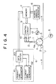
- a photographic material (hereinafter may be called a film for simplicity) F is transferred in the direction of the arrow A at a predetermined speed by being wound round a sprocket 4 under control of guide rollers 2 and 3.
- feed holes of the film F are hooked by pawls 4a of the sprocket 4.
- the shaft of the sprocket 4 is connected to a torque motor 5.
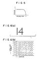
- the torque motor 5 has the torque characteristics shown in Fig. 5, and rotational force is provided to the sprocket 4 by the motor 5 in the opposite direction to the film transfer direction so as to apply stable back tension to the sprocket 4.
- each pawl 4a of the sprocket 4 is hooked at the edge of each feed hole of the film F on the opposite side to the feed direction, and the film F is transferred correctly at the transfer speed in the state that the film F is fixed to the surface of the sprocket 4 by the tension toward the downstream.
- the tension of the torque motor 5 may be used as forward tension instead of back tension.
- Tension may be applied by a powder brake, but a motor which can apply a tension during the suspension is preferable.
- Numeral 6 indicates a data input device which comprises a product kind (sensitivity, brand, size, etc.) designator 61, an element data generator 62 for generating letter data and character data, and a data editor 63. Data edited by the editor 63 is written in memory 7 comprising RAM or the like.
- the number of divided meaningful codes is 2.
- the number of divided codes may be more than 2.
- each dividing line is a boundary line between the bar and a blank space to keep the bar code accuracy.
- Each boundary line is managed by the storage holder for recording and holding the printing location on the photographic film F so as to be accurately printed at the correct location.
- the present invention provides a simplified apparatus which minimizes the bar code storage capacity of the RAM or others and reduces the production cost of the dot image writing and reading device.
- Data which is written in the memory, is addressed and read by a signal from an access address generator 8, latched by a control circuit 9, and printed on the film F by a printing device when a print timing pulse is received.
- This printing device comprises a LED group 10 comprising a plurality of LEDs which are independently turned on or off by the control circuit 9 and a fiber light guide member 12 for individually guiding light from each LED to a lens 11.
- the terminals of the light guide member 12 are lined, for example, at a pitch of several millimeters. This lining direction is perpendicular to the film F transfer direction. When the film F is located on the sprocket 4, dot images are printed on it in synchronization with the transfer.
- Numeral 13 indicates a rotary encoder which is connected to the shaft of the sprocket 4 and detects the rotation thereof, and the access address generator 8 outputs an address signal by a pulse from the encoder 13.
- the control circuit 9 also outputs a light emission command pulse (print timing pulse) by a signal from the encoder 13.
- Data of all the printing locations in the longitudinal direction (printing data line) of the film F to be printed is written in the memory 7, as shown in Figs. 6(a) and (b), in correspondence to the film length (which varies with the number of exposures, such as 12, 24, or 36 exposures). Symbols and others are generally printed at a predetermined pitch or at several locations. In this embodiment, however, dot information "1" is written in the address parts of the memory corresponding to the locations where the symbols and others are to be written, and dot information "0" is written in the other address parts. By doing this, data of all the data printing parts of the film from the start point to the end point in the longitudinal direction is written with "1" or "0" in the memory 7 in the address sequence.
- This operation is performed by a write data input device 6.
- one data input device 6, which is structurally separable, can be shared by those printers.
- the addresses stored in the memory 7 can be accessed in the address sequence for each predetermined pitch transfer by counting transfer detection pulses from the rotary encoder 13. Therefore, addressing the memory 7 requires no CPU or software, the access address generator 8 can comprise simple hardware, and the reading speed can be increased.
- data to be printed later is read from the memory 7 beforehand, latched in the control circuit 9, and printed when a printing command pulse for the data is received.
- Fig. 7 shows the timing chart thereof.
- the data preparation pulse is used to latch the data read from the memory 7 in the control circuit 9.
- a predetermined LED of the LED group 10 is selected and emits light.
- the emitted light is condensed by a lens 11 via the light guide member 12 and irradiated to the film F on the sprocket 4 for exposure.
- the latched data is all bit information "0"
- no data is printed even if the printing command pulse is received.
- symbols of dot images are printed on the film F.
- Latent images formed by exposure are developed simultaneously when the film F is developed by the user who purchases it.
- the present invention uses a method of preparing data to be printed beforehand, the time required for reading data from the memory 7 does not affect the printing time, no problems are imposed when the film F is transferred at a high speed, and the printing location can be managed accurately.
- Pawls 4a are formed, as shown in Fig. 8, on both sides of the sprocket 4, and data can be printed simultaneously on the outer sides of both pawls 4a. In this case, back tension is applied to the sprocket 4, and data is printed accurately at the printing location.
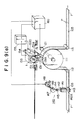
- a photographic material (long photographic film) F which is 35 mm in width and has perforations on its sides, is fed from the left in Fig. 10(a), conveyed to a puncher 140 and then to a feed drum 111 via a guide roller 112, sent to the right in the figure via a guide roller 113, and wound there (no take-up reel is shown).
- a sprocket drum may be conveniently used as a feed drum 111.
- An encoder 121 is directly connected to the feed drum 111, and used to detect the rotation angle of the drum and to pick up the feed amount of the film by the drum.
- This encoder 121 may be either an optical or magnetic encoder.
- a signal from the encoder 121 is supplied to a counter 160 which outputs a signal for each predetermined feed amount.
- the signal is supplied to a control unit 155 for a printer of numerals, alphabetic characters, and symbols such as bar codes.
- a printer drum 152 selects characters and symbols, and a stroboscopic light source 151 emits light.
- Necessary characters and symbols are printed at predetermined locations of the outer edges of the film on the feed drum by an optical system 131.
- printer drums there are various types of printer drums available.
- necessary characters and symbols are sufficiently contained in a negative or positive film f1 attached onto the drum
- a stepping motor 154 is operated by a signal from the counter 160 to allow the printer drum to selectively rotate to the location where the necessary characters and symbols are to be set, and the characters and symbols are printed by exposure on the outer edges of the film on the feed drum 111 by the optical system 131 through an exposure window which is formed at the location on a light shield box 153 where the optical axis is formed.
- This optical system may use a fiberscope besides the lens system as in this embodiment or a focusing light transmitter.
- the encoder 121 is not required.
- the rotation of the drum 111 or the film feed amount by the drive unit 167 is determined according to the pulse number.
- a drive pulse from the drive pulse generation control unit 165 is supplied to the drive unit 167 and the counter 160.
- characters and symbols to be printed on the film F on the feed drum 111 are selected, and the light emission timing and interval and the printing location interval on the film are determined.
- a length measurement notch 103 which is formed at each pitch of one roll film, simultaneously can be formed at a predetermined interval according to the predetermined count.
- a pulse motor may be used more preferably as a drive unit 167.
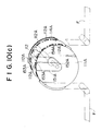
- a negative or positive film for contact exposure corresponding to the photographic material with symbols and characters printed shown in Fig. 1 is wound round the peripheral surface of a printer drum 111A.
- An exposure window 112A is formed on the peripheral surface of the printer drum 111A in correspondence with each character or symbol.
- the drum 111A contains an exposure cylinder 151A fixed to a rod 154A which is inserted and fixed to the frame of the main unit inside the rotation bearing of the drum.
- a light source lamp 152A is mounted inside the exposure cylinder, and an exposure window 153A is formed on the top of the cylinder in correspondence with the exposure window 112A on the drum 111A for characters and symbols.
- pawls 114A are mounted in correspondence with perforations P for correct positioning of a photographic material F.
- Such an apparatus requires many negative or positive films depending on the product kind and film length. To reduce the number of required negative or positive films as many as possible, it is desirable to set separate films on both sides of the drum.
- Each outer edge of such a photographic material (film) F on which codes are printed is an area with a narrow width. If the film F meanders during printing, printed codes are mislocated in the width direction. Such a phenomenon may cause a code sensor mounted at a predetermined location to misread codes.
- each bar code is printed so that the top thereof on the outer edge is outside the edge line of the photographic material F.
- each bar code of the film f1 is printed so that the top thereof on the outer edge is outside the edge line of the photographic material F as shown in Fig. 3(b).
- each bar code of the film f2 is printed so that the top thereof on the outer edge is outside the edge line of the photographic material F as shown in Fig. 3(b).
- each bar is printed fully up to the edge line, preventing the bar from being discontinued near the edge line. Therefore, misreading of each bar code is prevented.
- One of the separate negative or positive films which are used for both sides of the drum, are films with a bar code which is composed of a product kind code and a frame number code. Even if separate films are used, 1280 types of negative or positive films with composite bar codes are required, and the management thereof is complicated and troublesome.
- the composite bar code of the negative or positive film f1 attached on the printer drum 152 shown in Figs. 10(a) and 10(b) is replaced with a divided frame number bar code or a bar code of a negative or positive film F3 which is the frame number code connected with a parity and a stop bar code, and the printer drum 152 prints only the bar code of the film f3.
- a bar code for the product kind (maker and product names) code is printed and composed together with the start bar code at another location of the feed drum by a product kind code film f4.
- FIGs. 9(a) and 9(b) are perspective views showing such relations.
- a light shield box 153D which is provided with the product kind code film f4 at an exposure window 153E and a stroboscopic light source 151A therein is installed so that an image of the bar code at the connection end of the film f4 is printed by an optical system 131A at the printing location at a distance of a constant multiple pitch from the location of the connection end of the bar code which is printed on the film F on the feed drum via an exposure window 153A of the light shield box 153 containing both the printer drum 152, with the film f3 attached thereon and the stroboscopic light source 151, and the optical system 131.
- the stroboscopic light sources 151 and 151A emit light in synchronization with each other, though 151A is controlled by the control unit 155 so as to simultaneously emit light the constant multiple pitch time late for 151.
- each divided independent bar code is connected and composed without being shifted.
- the dividing line is a boundary line between a predetermined bar of the bar code, which is optionally selected, and a blank space; and it is necessary that this boundary line is accurately kept in place during composition.
- the product kind and frame bar code is divided into 2 codes. However, it can be divided into three or more independent bar codes for processing. Also in this case, only a small number of negative or positive film types are required.
- two divided negative or positive films are set at different locations for composing bar codes.
- a means used for another embodiment shown in Fig. 11 may be used.
- a negative or positive film with a bar code of the product kind code representing the start, maker name, and product name is fixed as a 1st divided film f4 so as to print it on the outer edge of the film F which is properly transferred
- a negative or positive film with a bar code representing the frame number, parity, and stop is fixed as a 2nd divided film f3
- about 80, 50, or 30 types of bar codes are arranged on the periphery of a printer disk 152F at an equal pitch.
- a signal from the counter 160 is supplied for each roll film (the length of one roll film of 12, 24, or 36 exposures) to a 1-revolution motor 148 of a notcher 140.
- a ram 142 which fixes a upper blade 142A via a crank 147, a crank rod 144, and crank pins 145 and 146, slides up and down within a column 141, the upper blade engages with a lower blade 143, and a length measurement notch 103 is formed on the edge of the film F which is stopped because a feed amount of one unit length is detected.
- a length measurement notch is formed continuously on the film edge unless the film is not stopped.
- a laser mark may be used or a mark may be printed.
- the laser mark or the printed mark is required to be searched for by the operator in a dark room. This method is slightly inconvenient compared with a mark of a length measurement notch 103, but can be used.
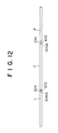
- each length measurement notch 103 which is formed, as shown in Fig. 12, on a photographic film F at the cutting location for each unit film, is formed in an area 104A which corresponds to a tongue tip 104 formed on each film and is cut off, no length measurement notches remain in the film. It is possible that the guide roller 112 is made movable instead of fixed, and used to adjust the path length of the film between the notcher 140 and the printer and also the relation between the notch and printing locations. Perforations are omitted in Fig. 12.
- the distance between the character and symbol printing location (e.g. around 131 in Fig. 9(a))on the film and the length measurement notch processing location(e.g. around 143 in Fig. 9(a)) is a multiple of the length of one roll film
- a phenomenon that the light source emits light many times can happen because unnecessary vibration of the film is detected during the length measurement notch processing and the suspension of the film conveyance.
- the negative or positive film may function as a mask. By doing this, default exposure can be prevented, even if multiple light emission occur.
- the notcher 140 is installed, as shown in Figs. 9(a) and 9(b), on the upstream side from the character and symbol printer in this embodiment. However, it may be installed on the downstream side.
- the present invention when color print hard copy is produced from a developed photographic film, the corresponding frame numbers are printed correctly and surely on the back of the hard copy, and the orderer or order receiver can specify picture planes surely, easily, efficiently, and readily for reprinting.
- the number of types of negative or positive films to be prepared can be extremely reduced by using negative or positive films of each bar code which is divided into a product kind code and a frame number code. By doing this, the switching time, negative or positive film management man-hour, and production cost can be greatly reduced.
- the storage capacity of a memory such as a RAM for storing divided bar codes can be extremely reduced, providing a compact and simplified apparatus and a remarkable reduction in cost.
- Each frame number can be read surely and correctly without disturbed by side notches, and can be surely printed on the back of each hard copy.
- the picture frame can be specified by the orderer or order receiver simply, surely, easily, efficiently, and readily.
Landscapes
- Physics & Mathematics (AREA)
- General Physics & Mathematics (AREA)
- Projection-Type Copiers In General (AREA)
Applications Claiming Priority (4)
| Application Number | Priority Date | Filing Date | Title |
|---|---|---|---|
| JP23022589A JPH0392848A (ja) | 1989-09-05 | 1989-09-05 | 撮影用ハロゲン化銀写真感光材料及び感光材料識別コード焼き込み方法 |
| JP230225/89 | 1989-09-05 | ||
| JP246012/89 | 1989-09-20 | ||
| JP24601289A JPH03107141A (ja) | 1989-09-20 | 1989-09-20 | 撮影用ハロゲン化銀写真感光材料への識別用バーコード焼き込み装置 |
Publications (2)
| Publication Number | Publication Date |
|---|---|
| EP0416519A2 true EP0416519A2 (de) | 1991-03-13 |
| EP0416519A3 EP0416519A3 (en) | 1992-10-07 |
Family
ID=26529218
Family Applications (1)
| Application Number | Title | Priority Date | Filing Date |
|---|---|---|---|
| EP19900116932 Withdrawn EP0416519A3 (en) | 1989-09-05 | 1990-09-04 | Silver halide photographic light-sensitive material and photographic light-sensitive material identification code printer |
Country Status (1)
| Country | Link |
|---|---|
| EP (1) | EP0416519A3 (de) |
Cited By (3)
| Publication number | Priority date | Publication date | Assignee | Title |
|---|---|---|---|---|
| EP0732621A3 (de) * | 1995-03-15 | 1997-01-02 | Minnesota Mining & Mfg | Photographische Film mit einem Mask-Strichcode |
| WO1999045431A1 (de) * | 1998-03-03 | 1999-09-10 | Bremaphot Biedebach & Co. (Gmbh & Co.) | Universelles photo-system |
| CN102411258A (zh) * | 2011-08-03 | 2012-04-11 | 上海电气核电设备有限公司 | 一种底片标识仪 |
Family Cites Families (4)
| Publication number | Priority date | Publication date | Assignee | Title |
|---|---|---|---|---|
| JPS59119422U (ja) * | 1983-02-02 | 1984-08-11 | 富士写真フイルム株式会社 | サイドプリント装置 |
| US4806965A (en) * | 1986-10-21 | 1989-02-21 | Konica Corporation | Apparatus for writing data onto photosensitive film |
| JP2578494B2 (ja) * | 1988-12-05 | 1997-02-05 | 富士写真フイルム株式会社 | 写真フィルム及びそのフレームナンバー続取方法 |
| US4965628A (en) * | 1989-06-28 | 1990-10-23 | Eastman Kodak Company | Photographic film with latent image multi-field bar code and eye-readable symbols |
-
1990
- 1990-09-04 EP EP19900116932 patent/EP0416519A3/en not_active Withdrawn
Cited By (4)
| Publication number | Priority date | Publication date | Assignee | Title |
|---|---|---|---|---|
| EP0732621A3 (de) * | 1995-03-15 | 1997-01-02 | Minnesota Mining & Mfg | Photographische Film mit einem Mask-Strichcode |
| WO1999045431A1 (de) * | 1998-03-03 | 1999-09-10 | Bremaphot Biedebach & Co. (Gmbh & Co.) | Universelles photo-system |
| CN102411258A (zh) * | 2011-08-03 | 2012-04-11 | 上海电气核电设备有限公司 | 一种底片标识仪 |
| CN102411258B (zh) * | 2011-08-03 | 2013-06-19 | 上海电气核电设备有限公司 | 一种底片标识仪 |
Also Published As
| Publication number | Publication date |
|---|---|
| EP0416519A3 (en) | 1992-10-07 |
Similar Documents
| Publication | Publication Date | Title |
|---|---|---|
| US4914471A (en) | Photographic printing method, apparatus therefor, and a strip of original film employed in the method and apparatus | |
| US3987467A (en) | Photographic film identification system | |
| EP0614117B1 (de) | Photographisches Behandlungsverfahren | |
| EP0827016A2 (de) | Verfahren und Vorrichtung zum Herstellen photographischer Abzüge mit Anzeigen für vorhandene, assozierte Toninformation | |
| KR0147815B1 (ko) | 필름상의 전용 자기 트랙들을 사용하여 사진처리하는 필름-비디오 플레이어 | |
| US5336873A (en) | Photographic film having frame number bar codes | |
| EP0416519A2 (de) | Silberhalogenid enthaltendes fotografisches lichtempfindliches Material und lichtempfindliches fotografisches Material identifizierender Kodedrucker | |
| US5179266A (en) | Photographic film and method of identifying frame numbers of photographic film | |
| US4937615A (en) | Photographic printing apparatus | |
| KR0129001B1 (ko) | 필름상의 전용 자기트랙을 이용하는 필름정보교환 시스템을 구비한 사진처리장치 | |
| JPH071371B2 (ja) | 写真焼付装置 | |
| JP2578494B2 (ja) | 写真フィルム及びそのフレームナンバー続取方法 | |
| JPH0829920A (ja) | 写真フイルム及びその検査方法 | |
| JPH0458013B2 (de) | ||
| JPH0392848A (ja) | 撮影用ハロゲン化銀写真感光材料及び感光材料識別コード焼き込み方法 | |
| JPH03107141A (ja) | 撮影用ハロゲン化銀写真感光材料への識別用バーコード焼き込み装置 | |
| JPH0685042B2 (ja) | 写真焼付方法 | |
| JP2968132B2 (ja) | 潜像形成方法 | |
| US5986777A (en) | Apparatus for reading or writing pixels on photographic film | |
| JPH05197011A (ja) | 情報記録・読取方式及びそれに用いるプリントヘッド | |
| JP2853560B2 (ja) | 写真焼付装置 | |
| JPH0224674A (ja) | 文字情報記録装置付きマイクロフイルム検索装置 | |
| JP2006065187A (ja) | 写真処理装置における消耗品管理システム | |
| JPH0442220A (ja) | フィルムのデータ焼込装置 | |
| JPS61232438A (ja) | 自動カラ−プリンタにおける露光デ−タ等を印画紙に焼付ける方法及び装置 |
Legal Events
| Date | Code | Title | Description |
|---|---|---|---|
| PUAI | Public reference made under article 153(3) epc to a published international application that has entered the european phase |
Free format text: ORIGINAL CODE: 0009012 |
|
| AK | Designated contracting states |
Kind code of ref document: A2 Designated state(s): DE GB |
|
| PUAL | Search report despatched |
Free format text: ORIGINAL CODE: 0009013 |
|
| AK | Designated contracting states |
Kind code of ref document: A3 Designated state(s): DE GB |
|
| 17P | Request for examination filed |
Effective date: 19930309 |
|
| STAA | Information on the status of an ep patent application or granted ep patent |
Free format text: STATUS: THE APPLICATION HAS BEEN WITHDRAWN |
|
| 18W | Application withdrawn |
Withdrawal date: 19940111 |