EP0416552A1 - Vertikalspindelständer - Google Patents
Vertikalspindelständer Download PDFInfo
- Publication number
- EP0416552A1 EP0416552A1 EP90117002A EP90117002A EP0416552A1 EP 0416552 A1 EP0416552 A1 EP 0416552A1 EP 90117002 A EP90117002 A EP 90117002A EP 90117002 A EP90117002 A EP 90117002A EP 0416552 A1 EP0416552 A1 EP 0416552A1
- Authority
- EP
- European Patent Office
- Prior art keywords
- vertical
- spindle
- column
- vertical column
- stand according
- Prior art date
- Legal status (The legal status is an assumption and is not a legal conclusion. Google has not performed a legal analysis and makes no representation as to the accuracy of the status listed.)
- Granted
Links
- 238000009749 continuous casting Methods 0.000 claims description 3
- 238000005553 drilling Methods 0.000 description 3
- 230000005540 biological transmission Effects 0.000 description 2
- 238000004873 anchoring Methods 0.000 description 1
- 238000010276 construction Methods 0.000 description 1
- 230000008878 coupling Effects 0.000 description 1
- 238000010168 coupling process Methods 0.000 description 1
- 238000005859 coupling reaction Methods 0.000 description 1
- 238000006073 displacement reaction Methods 0.000 description 1
- 238000003780 insertion Methods 0.000 description 1
- 230000037431 insertion Effects 0.000 description 1
- 238000003754 machining Methods 0.000 description 1
- 238000004519 manufacturing process Methods 0.000 description 1
- 238000003801 milling Methods 0.000 description 1
- 239000011295 pitch Substances 0.000 description 1
Images


Classifications
-
- B—PERFORMING OPERATIONS; TRANSPORTING
- B23—MACHINE TOOLS; METAL-WORKING NOT OTHERWISE PROVIDED FOR
- B23Q—DETAILS, COMPONENTS, OR ACCESSORIES FOR MACHINE TOOLS, e.g. ARRANGEMENTS FOR COPYING OR CONTROLLING; MACHINE TOOLS IN GENERAL CHARACTERISED BY THE CONSTRUCTION OF PARTICULAR DETAILS OR COMPONENTS; COMBINATIONS OR ASSOCIATIONS OF METAL-WORKING MACHINES, NOT DIRECTED TO A PARTICULAR RESULT
- B23Q11/00—Accessories fitted to machine tools for keeping tools or parts of the machine in good working condition or for cooling work; Safety devices specially combined with or arranged in, or specially adapted for use in connection with, machine tools
- B23Q11/001—Arrangements compensating weight or flexion on parts of the machine
- B23Q11/0017—Arrangements compensating weight or flexion on parts of the machine compensating the weight of vertically moving elements, e.g. by balancing liftable machine parts
- B23Q11/0025—Arrangements compensating weight or flexion on parts of the machine compensating the weight of vertically moving elements, e.g. by balancing liftable machine parts using resilient means, e.g. springs, hydraulic dampers
-
- B—PERFORMING OPERATIONS; TRANSPORTING
- B23—MACHINE TOOLS; METAL-WORKING NOT OTHERWISE PROVIDED FOR
- B23Q—DETAILS, COMPONENTS, OR ACCESSORIES FOR MACHINE TOOLS, e.g. ARRANGEMENTS FOR COPYING OR CONTROLLING; MACHINE TOOLS IN GENERAL CHARACTERISED BY THE CONSTRUCTION OF PARTICULAR DETAILS OR COMPONENTS; COMBINATIONS OR ASSOCIATIONS OF METAL-WORKING MACHINES, NOT DIRECTED TO A PARTICULAR RESULT
- B23Q1/00—Members which are comprised in the general build-up of a form of machine, particularly relatively large fixed members
- B23Q1/01—Frames, beds, pillars or like members; Arrangement of ways
- B23Q1/015—Frames, beds, pillars
-
- B—PERFORMING OPERATIONS; TRANSPORTING
- B23—MACHINE TOOLS; METAL-WORKING NOT OTHERWISE PROVIDED FOR
- B23Q—DETAILS, COMPONENTS, OR ACCESSORIES FOR MACHINE TOOLS, e.g. ARRANGEMENTS FOR COPYING OR CONTROLLING; MACHINE TOOLS IN GENERAL CHARACTERISED BY THE CONSTRUCTION OF PARTICULAR DETAILS OR COMPONENTS; COMBINATIONS OR ASSOCIATIONS OF METAL-WORKING MACHINES, NOT DIRECTED TO A PARTICULAR RESULT
- B23Q1/00—Members which are comprised in the general build-up of a form of machine, particularly relatively large fixed members
- B23Q1/25—Movable or adjustable work or tool supports
- B23Q1/44—Movable or adjustable work or tool supports using particular mechanisms
- B23Q1/48—Movable or adjustable work or tool supports using particular mechanisms with sliding pairs and rotating pairs
- B23Q1/4828—Movable or adjustable work or tool supports using particular mechanisms with sliding pairs and rotating pairs a single rotating pair followed parallelly by a single sliding pair
-
- Y—GENERAL TAGGING OF NEW TECHNOLOGICAL DEVELOPMENTS; GENERAL TAGGING OF CROSS-SECTIONAL TECHNOLOGIES SPANNING OVER SEVERAL SECTIONS OF THE IPC; TECHNICAL SUBJECTS COVERED BY FORMER USPC CROSS-REFERENCE ART COLLECTIONS [XRACs] AND DIGESTS
- Y10—TECHNICAL SUBJECTS COVERED BY FORMER USPC
- Y10T—TECHNICAL SUBJECTS COVERED BY FORMER US CLASSIFICATION
- Y10T29/00—Metal working
- Y10T29/51—Plural diverse manufacturing apparatus including means for metal shaping or assembling
- Y10T29/5104—Type of machine
- Y10T29/5109—Lathe
- Y10T29/5112—Convertible
-
- Y—GENERAL TAGGING OF NEW TECHNOLOGICAL DEVELOPMENTS; GENERAL TAGGING OF CROSS-SECTIONAL TECHNOLOGIES SPANNING OVER SEVERAL SECTIONS OF THE IPC; TECHNICAL SUBJECTS COVERED BY FORMER USPC CROSS-REFERENCE ART COLLECTIONS [XRACs] AND DIGESTS
- Y10—TECHNICAL SUBJECTS COVERED BY FORMER USPC
- Y10T—TECHNICAL SUBJECTS COVERED BY FORMER US CLASSIFICATION
- Y10T408/00—Cutting by use of rotating axially moving tool
- Y10T408/31—Convertible cutting means
-
- Y—GENERAL TAGGING OF NEW TECHNOLOGICAL DEVELOPMENTS; GENERAL TAGGING OF CROSS-SECTIONAL TECHNOLOGIES SPANNING OVER SEVERAL SECTIONS OF THE IPC; TECHNICAL SUBJECTS COVERED BY FORMER USPC CROSS-REFERENCE ART COLLECTIONS [XRACs] AND DIGESTS
- Y10—TECHNICAL SUBJECTS COVERED BY FORMER USPC
- Y10T—TECHNICAL SUBJECTS COVERED BY FORMER US CLASSIFICATION
- Y10T408/00—Cutting by use of rotating axially moving tool
- Y10T408/65—Means to drive tool
- Y10T408/675—Means to drive tool including means to move Tool along tool-axis
- Y10T408/6779—Rack and pinion
-
- Y—GENERAL TAGGING OF NEW TECHNOLOGICAL DEVELOPMENTS; GENERAL TAGGING OF CROSS-SECTIONAL TECHNOLOGIES SPANNING OVER SEVERAL SECTIONS OF THE IPC; TECHNICAL SUBJECTS COVERED BY FORMER USPC CROSS-REFERENCE ART COLLECTIONS [XRACs] AND DIGESTS
- Y10—TECHNICAL SUBJECTS COVERED BY FORMER USPC
- Y10T—TECHNICAL SUBJECTS COVERED BY FORMER US CLASSIFICATION
- Y10T409/00—Gear cutting, milling, or planing
- Y10T409/30—Milling
- Y10T409/309576—Machine frame
- Y10T409/309688—Machine frame including counterbalancing means
-
- Y—GENERAL TAGGING OF NEW TECHNOLOGICAL DEVELOPMENTS; GENERAL TAGGING OF CROSS-SECTIONAL TECHNOLOGIES SPANNING OVER SEVERAL SECTIONS OF THE IPC; TECHNICAL SUBJECTS COVERED BY FORMER USPC CROSS-REFERENCE ART COLLECTIONS [XRACs] AND DIGESTS
- Y10—TECHNICAL SUBJECTS COVERED BY FORMER USPC
- Y10T—TECHNICAL SUBJECTS COVERED BY FORMER US CLASSIFICATION
- Y10T82/00—Turning
- Y10T82/25—Lathe
- Y10T82/2572—Attachment
Definitions
- the present invention relates to a vertical spindle stand of the type mentioned in the preamble of claim 1.
- Lathes are often used in smaller workshops, which can be expanded to a vertical drilling and milling machine by installing a vertical spindle stand. As a result, the universality of such machines is considerably increased, so that they can be used for special machining tasks, in particular outside the production plant.
- the vertical spindle stand comprises a hollow vertical column on which a spindle housing is mounted so as to be vertically displaceable;
- a drawstring or the like is attached to the spindle housing, which is guided over a deflection roller attached to the upper end of the vertical column and the free end of which is connected to a tension spring arranged and anchored in the interior of the vertical column.
- This tension spring is protected inside the vertical column and housed in an aesthetically pleasing manner.
- the end of the tension spring facing away from the tension band is anchored in the vertical column itself, i.e. the tension spring does not have to be attached to the machine bed when mounting the vertical spindle stand or detached for dismantling the vertical spindle stand.
- the means for vertical adjustment of the spindle housing along the vertical column are supported on the vertical column itself, so that no connection to the remaining part of the lathe has to be created here either; the entire vertical spindle stand is a self-contained system, which is assembled as a whole on the machine bed of the lathe and is therefore immediately ready for use.
- the vertical column is preferably tubular, so that it can be produced in a simple manner as a turned part.
- the means for the vertical adjustment of the spindle housing comprise a lead screw which can be driven in rotation and which is rotatably and axially immovably mounted at the upper end of the vertical column and which a spindle nut fixedly arranged in the spindle housing interacts.
- This vertical lead screw enables a sensitive and precise adjustment of the spindle housing with the spindle stored in it.
- a vertical toothed rack fastened to the vertical column can be provided, which cooperates with a toothed pinion that is rotatably driven in the spindle housing.
- the pinion can be actuated, for example, via a pivot lever in a manner known in vertical drilling machines.
- the spindle housing is a section of a continuous casting with a strand axis running in the direction of the vertical column, the spindle housing being penetrated by a plurality of through openings running in the direction of the strand axis.
- One of the through openings has an inner contour adapted to the outer contour of the vertical column and serves to guide the spindle housing on the vertical column.
- Another of the through openings is designed for receiving the vertical spindle.
- the drive motor for the vertical spindle is arranged in a further through opening.
- the spindle nut for the vertical lead screw is fixedly arranged in a fourth through opening. Since it is a through hole, the vertical lead screw can penetrate it completely, i.e. the vertical lead screw and thus the vertical adjustment path of the spindle housing can be greater than the height of this spindle housing.
- the vertical leadscrew is preferably provided with a handwheel which is connected to an associated, Gear wheel that can be coupled to the vertical column is permanently connected to the vertical column.
- the feed drive for the vertical adjustment of the spindle housing and the spindle mounted therein can be carried out either manually or by motor.
- the gear wheel is formed in one piece with the handwheel, so that it can be produced, for example, in a simple manner as a precision injection-molded part.
- gear wheel is designed as a toothed belt pulley, which is connected via a toothed belt to a corresponding gear wheel fastened on the output shaft of the drive motor.
- a toothed belt can also be quickly assembled and disassembled using workshop equipment and by operators without special training for fitters. This makes it possible to separate the drive motor from the handwheel in the event that a manual feed drive is provided, so that the drive motor then does not have to be moved.
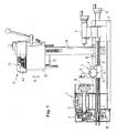
- Figure 1 shows a lathe 2 with a machine bed 3, a main headstock 4 fixed thereon with a motor-driven main spindle 5, further with a tailstock 6 slidably arranged in the direction of the main spindle axis and a cross table 7, which in a known manner one in the direction of the main spindle axis comprises longitudinally displaceable longitudinal table 8 and a transverse table 9 which can be displaced transversely thereto.
- a workpiece on which turning is to be carried out is clamped in the chuck 10 of the main spindle 5 and, if necessary, supported at its free end by the riding spindle of the riding stick 6.
- a tool for example a torsion bar, is clamped in a tool holder 11 attached to the cross table 9.
- a longitudinal lead screw 12 can be rotated with an external thread and is immovable in the axial direction 5 in the machine bed 3 and can be rotated by means of a handwheel 13 connected to it in a rotationally fixed manner.
- a transverse guide spindle is rotatably and axially immovably mounted in the longitudinal table 8 and can be rotated by means of a handwheel 14 which is arranged on this transverse guide spindle in a rotationally fixed manner.
- the cross lead screw with an external thread acts with a spindle nut fixedly arranged in the cross slide 9.
- the longitudinal lead screw 12 can be coupled to the main spindle 5 or the main spindle drive via a gear and coupling device 15 arranged at its end facing away from the handwheel 13, wherein different transmission ratios can be set to achieve different spiral pitches.
- a vertical spindle stand 17 can be inserted into a receiving fitting 16 of the machine bed 3.
- the vertical spindle stand 17 essentially comprises a vertical column 18, a spindle housing 20 which can be displaced in the vertical direction (double arrow 19) on the vertical column 18 and a vertical spindle 21 which is arranged in the spindle housing 20 and is coupled to a rotary drive (see FIG. 3).
- the vertical spindle 21, the spindle drive motor 22 and the transmission gear 23 designed as a pulley drive are firmly connected to the spindle housing 20 and move up and down with it.
- a tension band 24 is fastened to the spindle housing 20, which is guided over a deflection roller 26 which is mounted in a bearing block 25 arranged at the upper end of the vertical column 18, the free end 27 of the tension band 24 is connected to a tension spring 28 arranged in the interior of the hollow, tubular vertical column 18, the lower end of which is anchored in the vertical column 18 via anchoring means 29.
- the means for the vertical adjustment of the spindle housing 20 comprise a rotatable and in the bearing block 25 axially immovably mounted vertical lead screw 30, at the upper end of which a handwheel 31 is attached.
- the vertical lead screw 30 is provided with an external thread which interacts with the internal thread of a spindle nut 32 fixedly arranged in the spindle housing 20, so that the spindle housing 20 can be adjusted vertically in the direction of the double arrow 19 by rotating the vertical lead screw 30.
- a scale ring 34 is frictionally mounted on a hub-like extension 33 of the handwheel 31, a scale marking formed on the scale ring 34 having a e.g. on the bearing block 25 or on another machine-fixed component arranged countermark cooperates so that a fine adjustment of the spindle housing 20 is possible.
- an adjusting device is additionally provided, which essentially comprises a toothed rack 35 fastened to the vertical column 18, which cooperates with a toothed pinion which is rotatably mounted in the spindle housing 20 and can be actuated via the hand lever 36, as is known per se and therefore not shown in detail has been.
- This adjustment device essentially serves for the vertical adjustment of the vertical spindle during drilling operation.
- the spindle housing 20 is a section of a continuous casting with an axis running in the direction of the vertical column; it is penetrated by a plurality of through openings running in the direction of the strand axis, which serve to receive the different units arranged in the spindle housing 20 and to support displacement on the vertical column 18.
- a first through opening 37 has a cross section (see FIG. 4) accordingly an inner contour adapted to the outer contour of the vertical column 18, the outer contour of the vertical column 18 also including the rack 35.
- the through opening 37 can be made with great accuracy when the spindle housing 20 is continuously cast. The finishing can easily be done by turning and pushing.
- a second through opening 38 serves to receive the vertical spindle 21 or the spindle bearing 39.
- a third through opening 40 receives the spindle nut 32 and the vertical lead screw 30, which can pass through this through opening 40 over its entire length.
- a fourth through opening 41 serves to receive the spindle drive motor 22.
- a section serving as a toothed belt pulley 42 is formed on the handwheel 31 of the vertical lead screw 30, which section can be connected via a toothed belt to a servomotor which, for example, is firmly connected to the bearing block 25.
- a servomotor which, for example, is firmly connected to the bearing block 25.
- the servomotor can be connected to an NC control so that the operation of the vertical spindle stand 17 can be automated.
- the top of the spindle housing 21 can be covered by a cover 43, from which essentially only the handwheel 31 protrudes.
- the vertical column 18 is provided in its lower region with a stop pin 44 which, when the vertical spindle stand 17 is mounted, lies on a counter surface of the receiving fitting 16 and thus defines the insertion depth of the vertical column 18 in the receiving fitting 16.
- two circumferential grooves 45 are formed in the region of the lower end of the vertical column 18, into which fixing screws (not shown) can engage for an axial fixing of the vertical spindle stand 17.
Landscapes
- Engineering & Computer Science (AREA)
- Mechanical Engineering (AREA)
- Machine Tool Units (AREA)
- Turning (AREA)
- Toys (AREA)
- Pens And Brushes (AREA)
- Spinning Or Twisting Of Yarns (AREA)
- Drilling And Boring (AREA)
Abstract
Description
- Die vorliegende Erfindung betrifft einen Vertikalspindelständer der im Oberbegriff des Ansprüches 1 genannten Art.
- In kleineren Werkstätten werden vielfach Drehmaschinen eingesetzt, die durch Anmontieren eines Vertikalspindelständers zu einer Vertikalbohr- und Fräsmaschine ergänzt werden können. Dadurch wird die Universalität derartiger Maschinen beträchtlich erhöht, so daß sie insbesondere außerhalb des Produktionsbetriebes für Sonderbearbeitungsaufgaben eingesetzt werden können.
- Da derartige Vertikalspindelständer vor allem in Verbindung mit kleineren Drehmaschinen der unteren Preisklasse Verwendung finden, ist es wesentlich, daß auch der Vertikalspindelständer konstruktiv einfach und damit preiswert ist. Um die Universalität der Gesamtmaschine optimal nutzen zu können, ist es weiter wichtig, daß der Vertikalspindelständer leicht und ohne großen Zeitaufwand montiert und demontiert werden kann.
- Es ist deshalb die Aufgabe der vorliegenden Erfindung, einen Vertikalspindelständer der im Oberbegriff des Anspruches 1 genannten Art zu schaffen, welcher einfach im Aufbau und damit preisgünstig ist und der sich einfach und schnell montieren bzw. demontieren läßt.
- Diese Aufgabe ist erfindungsgemäß durch die im Kennzeichen des Ansprüches 1 enthaltenen Merkmale gelöst.
- Der Vertikalspindelständer umfaßt eine hohle Vertikalsäule, auf welcher ein Spindelgehäuse vertikal verschiebbar gelagert ist; um das Gewicht des Spindelgehäuses mit allen Einbauten auszugleichen, ist am Spindelgehäuse ein Zugband oder dergleichen befestigt, welches über eine am oberen Ende der Vertikalsäule befestigte Umlenkrolle geführt und dessen freies Ende mit einer im Inneren der Vertikalsäule angeordneten und verankerten Zugfeder verbunden ist. Diese Zugfeder ist im Inneren der Vertikalsäule geschützt und in ästhetisch ansprechender Weise untergebracht. Das dem Zugband abgewandte Ende der Zugfeder ist in der Vertikalsäule selbst verankert, d.h. die Zugfeder muß nicht bei der Montage des Vertikalspindelständers am Maschinenbett eingehängt bzw. zum Demontieren des Vertikalspindelständers ausgehängt werden. Die Mittel zur vertikalen Verstellung des Spindelgehäuses entlang der Vertikalsäule stützen sich an der Vertikalsäule selbst ab, so daß auch hier keine Verbindung zum übrigen Teil der Drehmaschine geschaffen werden muß; der gesamte Vertikalspindelständer ist ein in sich geschlossenes System, welches als ganzes am Maschinenbett der Drehmaschine montiert wird und damit sofort einsatzbereit ist.
- Die Vertikalsäule ist vorzugsweise rohrförmig ausgebildet, so daß sie in einfacher Weise als Drehteil herstellbar ist.
- Die Mittel zur vertikalen Verstellung des Spindelgehäuses umfassen erfindungsgemäß eine Drehantreibbare Leitspindel, die am oberen Ende der Vertikalsäule drehbar und axial unverschiebbar gelagert ist und die mit einer im Spindelgehäuse fest angeordneten Spindelmutter zusammenwirkt. Diese Vertikalleitspindel ermöglicht ein feinfühliges und genaues Verstellen des Spindelgehäuses mit der darin gelagerten Spindel.
- Zusätzlich kann eine an der Vertikalsäule befestigte vertikale Zahnstange vorgesehen sein, welche mit einem im Spindelgehäuse drehantreibbar gelagerten Zahnritzel zusammenwirkt. Das Zahnritzel kann beispielsweise über einen Schwenkhebel in bei Vertikalbohrmaschinen bekannter Weise betätigbar sein.
- Das Spindelgehäuse ist in bevorzugter Ausgestaltung der Erfindung ein Abschnitt eines Stranggußteils mit einer in Richtung der Vertikalsäule verlaufenden Strangachse, wobei das Spindelgehäuse von mehreren in Richtung der Strangachse verlaufenden Durchgangsöffnungen durchsetzt ist. Eine der Durchgangsöffnungen hat eine der Außenkontur der Vertikalsäule angepaßte Innenkontur und dient zur Führung des Spindelgehäuses auf der Vertikalsäule.
- Eine andere der Durchgangsöffnungen ist für die Aufnahme der Vertikalspindel ausgebildet. In einer weiteren Durchgangsöffnung ist der Antriebsmotor für die Vertikalspindel angeordnet. In einer vierten Durchgangsöffnung ist die Spindelmutter für die Vertikalleitspindel fest angeordnet. Da es sich um eine Durchgangsöffnung handelt, kann die Vertikalleitspindel diese ganz durchsetzen, d.h. die Vertikalleitspindel und damit der vertikale Verstellweg des Spindelgehäuses kann größer sein als die Höhe dieses Spindelgehäuses.
- Die Vertikalleitspindel ist vorzugsweise mit einem Handrad versehen, das mit einem an einem zugeordneten, an der Vertikalsäule fest montierten Stellmotor ankuppelbaren Getrieberad fest verbunden ist. Auf diese Weise kann der Vorschubantrieb für die vertikale Verstellung des Spindelgehäuses und der darin gelagerten Spindel wahlweise manuell oder motorisch durchgeführt werden.
- In bevorzugter Ausgestaltung der Erfindung ist das Getrieberad mit dem Handrad einstückig ausgebildet, so daß es zum Beispiel in einfacher Weise als Präzisionsspritzteil hergestellt werden kann.
- Eine besonders einfache konstruktive Ausführung ergibt sich dann, wenn das Getrieberad als Zahnriemenscheibe ausgebildet ist, die über einen Zahnriemen mit einem entsprechenden, auf der Ausgangswelle des Antriebsmotors befestigten Zahnrad verbunden wird. Ein Zahnriemen läßt sich in einfacher Weise auch mit Werkstattmitteln und von Bedienungspersonen ohne spezielle Monteurausbildung schnell montieren bzw. demontieren. Damit besteht die Möglichkeit, den Antriebsmotor für den Fall, daß ein manueller Vorschubantrieb vorgesehen ist, von dem Handrad zu trennen, so daß dann der Antriebsmotor nicht mitbewegt zu werden braucht.
- Ein Ausführungsbeispiel der Erfindung ist in der Zeichnung dargestellt und im folgenden näher beschrieben. Es zeigen:
- Figur 1 eine Drehmaschine mit am Maschinenbett anmontiertem Vertikalspindelständer;
- Figur 2 einen Vertikalspindelständer gemäß Figur 1 in vergrößertem Maßstab;
- Figur 3 einen Vertikalspindelständer gemäß Figur 2 in einer Seitenansicht;
- Figur 4 einen Vertikalspindelständer gemäß Figur 1 in einer Draufsicht.
- Figur 1 zeigt eine Drehmaschine 2 mit einem Maschinenbett 3, einem darauf fest angeordneten Hauptspindelstock 4 mit einer motorgetriebenen Hauptspindel 5, ferner mit einem in Richtung der Hauptspindelachse verschiebbar angeordneten Reitstock 6 und einem Kreuztisch 7, welcher in an sich bekannter Weise einen in Richtung der Hauptspindelachse längsverschiebbaren Längstisch 8 und einen auf diesem quer dazu verfahrbaren Quertisch 9 umfaßt. Ein Werkstück, an welchem eine Drehbearbeitung durchgeführt werden soll, wird in das Spannfutter 10 der Hauptspindel 5 eingespannt und gegebenenfalls an seinem freien Ende durch die Reitspindel des Reitstokkes 6 abgestützt. In einem am Quertisch 9 befestigten Werkzeughalter 11 wird ein Werkzeug, beispielsweise ein Drehstab, eingespannt.
- Für die Verstellung des Längstisches 8 ist eine Längsleitspindel 12 mit einem Außengewinde drehbar und in axialer Richtung 5 unverschiebbar im Maschinenbett 3 gelagert und über ein mit dieser drehfest verbundenes Handrad 13 verdrehbar. Die mit einem Außengewinde versehene Längsleitspindel 12 wirkt mit einer im Längstisch 8 fest angeordneten Spindelmutter zusammen.
- Zur Verstellung des Quertisches 9 ist im Längstisch 8 eine Querleitspindel drehbar und axial unverschiebbar gelagert, die mittels eines an dieser Querleitspindel drehfest angeordneten Handrades 14 verdrehbar ist. Die mit einem Außengewinde versehene Querleitspindel wirkt mit einer im Querschlitten 9 fest angeordneten Spindelmutter zusammen.
- Um Spiraldreharbeiten durchführen zu können, kann die Längsleitspindel 12 über eine an ihrem dem Handrad 13 abgewandten Ende angeordnete Getriebe- und Kupplungseinrichtung 15 mit der Hauptspindel 5 bzw. dem Hauptspindelantrieb gekuppelt werden, wobei unterschiedliche Übersetzungsverhältnisse zur Erzielung unterschiedlicher Spiralsteigungen einstellbar sind.
- In einen Aufnahmebeschlag 16 des Maschinenbettes 3 ist ein Vertikalspindelständer 17 einsetzbar. Der Vertikalspindelständer 17 umfaßt im wesentlichen eine Vertikalsäule 18, ein auf der Vertikalsäule 18 in vertikaler Richtung (Doppelpfeil 19) verschiebbares Spindelgehäuse 20 und eine in dem Spindelgehäuse 20 angeordnete, mit einem Drehantrieb gekoppelte Vertikal-spindel 21 (siehe Figur 3). Die Vertikalspindel 21, der Spindelantriebsmotor 22 und das als Riemenscheibentrieb ausgebildete Übertragungsgetriebe 23 sind fest mit dem Spindelgehäuse 20 verbunden und bewegen sich mit diesem auf und ab.
- Um einen Gewichtsausgleich für das Spindelgehäuse 20 mit allen Einbauten zu schaffen, ist am Spindelgehäuse 20 ein Zugband 24 befestigt, welches über eine Umlenkrolle 26 geführt ist, die in einem am oberen Ende der Vertikalsäule 18 angeordneten Lagerbock 25 gelagert ist, wobei das freie Ende 27 des Zugbandes 24 mit einer im Inneren der hohlen, rohrförmigen Vertikalsäule 18 angeordneten Zugfeder 28 verbunden ist, deren unteres Ende in der Vertikalsäule 18 über Verankerungsmittel 29 verankert ist.
- Die Mittel zur vertikalen Verstellung des Spindelgehäuses 20 umfassen eine im Lagerbock 25 drehbar und axial unverschiebbar gelagerte Vertikalleitspindel 30, an deren oberem Ende ein Handrad 31 befestigt ist. Die Vertikalleitspindel 30 ist mit einem Außengewinde versehen, welches mit dem Innengewinde einer im Spindelgehäuse 20 fest angeordneten Spindelmutter 32 zusammenwirkt, so daß durch Verdrehen der Vertikal-leitspindel 30 das Spindelgehäuse 20 in Richtung des Doppelpfeiles 19 vertikal verstellt werden kann.
- Auf einem nabenartigen Fortsatz 33 des Handrades 31 ist ein Skalenring 34 reibschlüssig gelagert, wobei eine auf dem Skalenring 34 ausgebildete Skalenmarkierung mit einer z.B. am Lagerbock 25 oder an einem anderen maschinenfesten Bauteil angeordneten Gegenmarkierung zusammenwirkt, so daß eine Feinverstellung des Spindelgehäuses 20 möglich ist.
- Zur Grobverstellung des Spindelgehäuses 20 ist zusätzlich eine Verstelleinrichtung vorgesehen, die im wesentlichen eine an der Vertikalsäule 18 befestigte Zahnstange 35 umfaßt, die mit einem im Spindelgehäuse 20 drehbar gelagerten und über den Handhebel 36 betätigbaren Zahnritzel zusammenwirkt, wie an sich bekannt und deshalb nicht näher dargestellt wurde. Diese Verstelleinrichtung dient im wesentlichen zur Vertikalverstellung der Vertikalspindel beim Bohrbetrieb.
- Das Spindelgehäuse 20 ist ein Abschnitt eines Stranggußteils mit einer in Richtung der Vertikalsäule verlaufenden Strangachse; es ist von mehreren in Richtung der Strangachse verlaufenden Durchgangsöffnungen durchsetzt, die zur Aufnahme der unterschiedlichen, im Spindelgehäuse 20 angeordneten Aggregate sowie zur Verschiebelagerung auf der Vertikalsäule 18 dienen.
- Eine erste Durchgangsöffnung 37 hat im Querschnitt (siehe Figur 4) dementsprechend eine der Außenkontur der Vertikalsäule 18 angepaßte Innenkontur, wobei die Außenkontur der Vertikalsäule 18 auch die Zahnstange 35 mitumfaßt. Die Durchgangsöffnung 37 kann beim Stranggießen des Spindelgehäuses 20 schon mit großer Genauigkeit hergestellt sein. Die Fertigbearbeitung kann in einfacher Weise durch Drehen und Stoßen erfolgen.
- Eine zweite Durchgangsöffnung 38 (siehe Figur 3) dient zur Aufnahme der Vertikalspindel 21 bzw. der Spindellager 39.
- Eine dritte Durchgangsöffnung 40 nimmt die Spindelmutter 32 auf sowie die Vertikalleitspindel 30, die diese Durchgangsöffnung 40 auf ihrer ganzen Länge durchsetzen kann.
- Eine vierte Durchgangsöffnung 41 dient zur Aufnahme des Spindelantriebsmotors 22.
- Wie insbesondere Figur 3 zeigt, ist am Handrad 31 der Vertikalleitspindel 30 ein als Zahnriemenscheibe 42 dienender Abschnitt ausgebildet, welcher über einen Zahnriemen mit einem Stellmotor verbunden werden kann, welcher beispielsweise mit dem Lagerbock 25 fest verbunden wird. Auf diese Weise ist eine motorische Verstellung des Spindelgehäuses 20 möglich. Der Stellmotor kann mit einer NC-Steuerung verbunden sein, so daß der Betrieb des Vertikalspindelständers 17 automatisierbar ist.
- Wie die Figuren 1 und 2 zeigen, kann die Oberseite des Spindelgehäuses 21 durch einen Deckel 43 abgedeckt werden, aus welchem im wesentlichen nur das Handrad 31 herausragt.
- Die Vertikalsäule 18 ist in ihrem untere Bereich mit einem Anschlagstift 44 versehen, welcher sich bei der Montage des Vertikalspindelständers 17 auf eine Gegenfläche des Aufnahmebeschlages 16 auf legt und damit die Einstecktiefe der Vertikalsäule 18 im Aufnahmebeschlag 16 definiert. Außerdem sind im Bereich des unteren Endes der Vertikalsäule 18 zwei Umfangsnuten 45 ausgebildet, in die nicht dargestellte Fixierschrauben für eine axiale Fixierung des Vertikalspindelständers 17 eingreifen können.
Claims (12)
Priority Applications (1)
| Application Number | Priority Date | Filing Date | Title |
|---|---|---|---|
| AT90117002T ATE90245T1 (de) | 1989-09-06 | 1990-09-04 | Vertikalspindelstaender. |
Applications Claiming Priority (2)
| Application Number | Priority Date | Filing Date | Title |
|---|---|---|---|
| DE3929657 | 1989-09-06 | ||
| DE3929657A DE3929657A1 (de) | 1989-09-06 | 1989-09-06 | Vertikalspindelstaender |
Publications (2)
| Publication Number | Publication Date |
|---|---|
| EP0416552A1 true EP0416552A1 (de) | 1991-03-13 |
| EP0416552B1 EP0416552B1 (de) | 1993-06-09 |
Family
ID=6388773
Family Applications (1)
| Application Number | Title | Priority Date | Filing Date |
|---|---|---|---|
| EP90117002A Expired - Lifetime EP0416552B1 (de) | 1989-09-06 | 1990-09-04 | Vertikalspindelständer |
Country Status (5)
| Country | Link |
|---|---|
| US (1) | US5090279A (de) |
| EP (1) | EP0416552B1 (de) |
| JP (1) | JPH03149101A (de) |
| AT (1) | ATE90245T1 (de) |
| DE (2) | DE3929657A1 (de) |
Families Citing this family (8)
| Publication number | Priority date | Publication date | Assignee | Title |
|---|---|---|---|---|
| JP2000117697A (ja) * | 1998-10-13 | 2000-04-25 | Carl Manufacturing Co Ltd | 孔明け装置 |
| US6557226B1 (en) * | 1999-04-23 | 2003-05-06 | Michael E. Landry | Apparatus for manufacturing a bone dowel |
| US6442814B1 (en) | 1999-04-23 | 2002-09-03 | Spinal Concepts, Inc. | Apparatus for manufacturing a bone dowel |
| US6676323B2 (en) * | 2000-12-29 | 2004-01-13 | The Minster Machine Company | Adjustable clamping device in a mechanical press |
| FR2929145B1 (fr) * | 2008-03-27 | 2010-03-12 | Numalliance | Poste d'amenage |
| DE102014100788A1 (de) | 2014-01-24 | 2015-07-30 | Emco Maier Ges.M.B.H. | Drehmaschine zum Langdrehen ohne Lünette |
| CN105619076A (zh) * | 2014-10-28 | 2016-06-01 | 富鼎电子科技(嘉善)有限公司 | 复合加工装置 |
| US12057755B2 (en) * | 2020-01-29 | 2024-08-06 | Hougen Manufacturing, Inc. | Electric motor power cord for portable electrical assembly |
Citations (8)
| Publication number | Priority date | Publication date | Assignee | Title |
|---|---|---|---|---|
| AT134803B (de) * | 1931-11-16 | 1933-10-10 | Ernst Krause & Co Aktiengessel | Kombinierte Werkzeugmaschine. |
| DE830248C (de) * | 1950-12-09 | 1952-02-04 | Mafell Maschinenfabrik Inh Dip | Auf das Werkstueck aufsetzbare Holzbohrmaschine |
| AT189886B (de) * | 1955-05-03 | 1957-05-10 | Stefan Jakoblits | Mehrzweck-Werkstättenmaschine |
| DE2553805A1 (de) * | 1975-11-29 | 1977-06-08 | Jahn Eberhard | Fraeseinrichtung fuer drehbaenke |
| EP0117973A2 (de) * | 1983-01-10 | 1984-09-12 | Maier & Co. | Bausatz für Kleinwerkzeugmaschinen |
| EP0142976A2 (de) * | 1983-11-16 | 1985-05-29 | Shopsmith Inc. | Mehrweck-Holzbearbeitungsmaschine |
| DE3700816A1 (de) * | 1987-01-14 | 1988-07-28 | Klaus Seite | Apparat zur zusaetzlichen ausruestung einer drehmaschine im sinne einer universalbohrmaschine |
| DD274994A1 (de) * | 1988-08-25 | 1990-01-10 | Jenapharm Veb | Universell einsetzbare hoehefraes-, bohr- und schleifspindel |
Family Cites Families (5)
| Publication number | Priority date | Publication date | Assignee | Title |
|---|---|---|---|---|
| US1928756A (en) * | 1930-04-22 | 1933-10-03 | Henry Sundermann H | Spindle guide bracket |
| US1916618A (en) * | 1930-05-24 | 1933-07-04 | Rapid Tool Corp | Cylinder grinding stand |
| US2084686A (en) * | 1935-06-21 | 1937-06-22 | Frank L Howard | Sample taking machine |
| DE2629431C2 (de) * | 1976-06-30 | 1981-10-08 | Friedrich Wilhelm 8900 Augsburg Ortmann | Schlittenständereinheit für Sonderwerkzeugmaschinen |
| US4279553A (en) * | 1979-03-09 | 1981-07-21 | Ralph A. Heineman | Machine tool column mount |
-
1989
- 1989-09-06 DE DE3929657A patent/DE3929657A1/de not_active Withdrawn
-
1990
- 1990-09-04 US US07/578,589 patent/US5090279A/en not_active Expired - Fee Related
- 1990-09-04 DE DE9090117002T patent/DE59001690D1/de not_active Expired - Fee Related
- 1990-09-04 AT AT90117002T patent/ATE90245T1/de not_active IP Right Cessation
- 1990-09-04 EP EP90117002A patent/EP0416552B1/de not_active Expired - Lifetime
- 1990-09-06 JP JP2234625A patent/JPH03149101A/ja active Pending
Patent Citations (8)
| Publication number | Priority date | Publication date | Assignee | Title |
|---|---|---|---|---|
| AT134803B (de) * | 1931-11-16 | 1933-10-10 | Ernst Krause & Co Aktiengessel | Kombinierte Werkzeugmaschine. |
| DE830248C (de) * | 1950-12-09 | 1952-02-04 | Mafell Maschinenfabrik Inh Dip | Auf das Werkstueck aufsetzbare Holzbohrmaschine |
| AT189886B (de) * | 1955-05-03 | 1957-05-10 | Stefan Jakoblits | Mehrzweck-Werkstättenmaschine |
| DE2553805A1 (de) * | 1975-11-29 | 1977-06-08 | Jahn Eberhard | Fraeseinrichtung fuer drehbaenke |
| EP0117973A2 (de) * | 1983-01-10 | 1984-09-12 | Maier & Co. | Bausatz für Kleinwerkzeugmaschinen |
| EP0142976A2 (de) * | 1983-11-16 | 1985-05-29 | Shopsmith Inc. | Mehrweck-Holzbearbeitungsmaschine |
| DE3700816A1 (de) * | 1987-01-14 | 1988-07-28 | Klaus Seite | Apparat zur zusaetzlichen ausruestung einer drehmaschine im sinne einer universalbohrmaschine |
| DD274994A1 (de) * | 1988-08-25 | 1990-01-10 | Jenapharm Veb | Universell einsetzbare hoehefraes-, bohr- und schleifspindel |
Also Published As
| Publication number | Publication date |
|---|---|
| DE59001690D1 (de) | 1993-07-15 |
| DE3929657A1 (de) | 1991-03-07 |
| ATE90245T1 (de) | 1993-06-15 |
| JPH03149101A (ja) | 1991-06-25 |
| US5090279A (en) | 1992-02-25 |
| EP0416552B1 (de) | 1993-06-09 |
Similar Documents
| Publication | Publication Date | Title |
|---|---|---|
| DE3328327C2 (de) | Vorrichtung zum spanabhebenden Bearbeiten eines Werkstücks sowie NC-gesteuerte Drehmaschine zur Druchführung eines solchen Verfahrens | |
| DE2535135C2 (de) | ||
| CH679841A5 (de) | ||
| DE3723133C1 (de) | Fraes-Werkzeug fuer eine numerisch gesteuerte Werkzeugmaschine zum Herstellen einer profilierten aufgeweiteten Bohrung | |
| EP0416552B1 (de) | Vertikalspindelständer | |
| EP0335084B1 (de) | Vorrichtung und Werkzeug zur Herstellung aller bekannten Gewindearten (ausser Sägegewinde) in einem Arbeitsgang | |
| DE3929659A1 (de) | Drehmaschine | |
| AT395835B (de) | Verfahren zum herstellen einer parallelachsigen rotationskolbenmaschine | |
| DE1173766B (de) | Horizontal-Fraes- und -Bohrwerk, insbesondere Gesenkfraesmaschine | |
| DE3725014C2 (de) | ||
| EP1025953A1 (de) | Werkzeugmaschine | |
| EP0145703B1 (de) | Querschlitten für eine Drehmaschine | |
| DE2636986A1 (de) | Drehbank | |
| DE3810884C1 (en) | Apparatus for producing internal threads without predrilling in the solid material | |
| DE19710447A1 (de) | Vorrichtung zur Werkstückzuführung in einen Einspannbereich einer Werkzeugmaschine | |
| DE3843795C2 (de) | ||
| DE10139296A1 (de) | Spannvorrichtung für mehrseitig zu bearbeitende Werkstücke | |
| DE3226244A1 (de) | Verfahren und einrichtung zum ausgleich des werkzeugverschleisses bei einer bohrstange | |
| DE2640797A1 (de) | Kraftbetaetigter reitstock | |
| DE3416217C2 (de) | ||
| DE3139366A1 (de) | Praezisionsschleifmaschine | |
| DE3721732A1 (de) | Vorrichtung zum gewinde-wirbelschneiden | |
| DE4215419A1 (de) | Numerisch gesteuertes Aufsatzgerät für eine spanabhebende Werkzeugmaschine | |
| DE8804806U1 (de) | Vorrichtung und Werkzeug zur Herstellung aller bekannten Gewindearten (außer Sägegewinde) in einem Arbeitsgang | |
| DE2619910C2 (de) | Revolverdrehbank |
Legal Events
| Date | Code | Title | Description |
|---|---|---|---|
| PUAI | Public reference made under article 153(3) epc to a published international application that has entered the european phase |
Free format text: ORIGINAL CODE: 0009012 |
|
| 17P | Request for examination filed |
Effective date: 19901210 |
|
| AK | Designated contracting states |
Kind code of ref document: A1 Designated state(s): AT BE CH DE DK ES FR GB GR IT LI LU NL SE |
|
| RAP1 | Party data changed (applicant data changed or rights of an application transferred) |
Owner name: EMCO MAIER GESELLSCHAFT M.B.H. |
|
| 17Q | First examination report despatched |
Effective date: 19920925 |
|
| GRAA | (expected) grant |
Free format text: ORIGINAL CODE: 0009210 |
|
| AK | Designated contracting states |
Kind code of ref document: B1 Designated state(s): AT BE CH DE DK ES FR GB GR IT LI LU NL SE |
|
| PG25 | Lapsed in a contracting state [announced via postgrant information from national office to epo] |
Ref country code: IT Free format text: LAPSE BECAUSE OF FAILURE TO SUBMIT A TRANSLATION OF THE DESCRIPTION OR TO PAY THE FEE WITHIN THE PRE;WARNING: LAPSES OF ITALIAN PATENTS WITH EFFECTIVE DATE BEFORE 2007 MAY HAVE OCCURRED AT ANY TIME BEFORE 2007. THE CORRECT EFFECTIVE DATE MAY BE DIFFERENT FROM THE ONE RECORDED.SCRIBED TIME-LIMIT Effective date: 19930609 Ref country code: NL Effective date: 19930609 Ref country code: FR Effective date: 19930609 Ref country code: GB Effective date: 19930609 Ref country code: SE Effective date: 19930609 Ref country code: BE Effective date: 19930609 Ref country code: GR Free format text: LAPSE BECAUSE OF FAILURE TO SUBMIT A TRANSLATION OF THE DESCRIPTION OR TO PAY THE FEE WITHIN THE PRESCRIBED TIME-LIMIT Effective date: 19930609 Ref country code: DK Effective date: 19930609 Ref country code: ES Free format text: THE PATENT HAS BEEN ANNULLED BY A DECISION OF A NATIONAL AUTHORITY Effective date: 19930609 |
|
| REF | Corresponds to: |
Ref document number: 90245 Country of ref document: AT Date of ref document: 19930615 Kind code of ref document: T |
|
| REF | Corresponds to: |
Ref document number: 59001690 Country of ref document: DE Date of ref document: 19930715 |
|
| PG25 | Lapsed in a contracting state [announced via postgrant information from national office to epo] |
Ref country code: AT Effective date: 19930904 |
|
| PGFP | Annual fee paid to national office [announced via postgrant information from national office to epo] |
Ref country code: DE Payment date: 19930915 Year of fee payment: 4 |
|
| PG25 | Lapsed in a contracting state [announced via postgrant information from national office to epo] |
Ref country code: CH Effective date: 19930930 Ref country code: LI Effective date: 19930930 Ref country code: LU Free format text: LAPSE BECAUSE OF NON-PAYMENT OF DUE FEES Effective date: 19930930 |
|
| EN | Fr: translation not filed | ||
| NLV1 | Nl: lapsed or annulled due to failure to fulfill the requirements of art. 29p and 29m of the patents act | ||
| GBV | Gb: ep patent (uk) treated as always having been void in accordance with gb section 77(7)/1977 [no translation filed] |
Effective date: 19930609 |
|
| PLBE | No opposition filed within time limit |
Free format text: ORIGINAL CODE: 0009261 |
|
| STAA | Information on the status of an ep patent application or granted ep patent |
Free format text: STATUS: NO OPPOSITION FILED WITHIN TIME LIMIT |
|
| REG | Reference to a national code |
Ref country code: CH Ref legal event code: PL |
|
| 26N | No opposition filed | ||
| PG25 | Lapsed in a contracting state [announced via postgrant information from national office to epo] |
Ref country code: DE Effective date: 19950601 |