EP0416663A2 - Daten-Aufzeichnungsgerät - Google Patents
Daten-Aufzeichnungsgerät Download PDFInfo
- Publication number
- EP0416663A2 EP0416663A2 EP90117393A EP90117393A EP0416663A2 EP 0416663 A2 EP0416663 A2 EP 0416663A2 EP 90117393 A EP90117393 A EP 90117393A EP 90117393 A EP90117393 A EP 90117393A EP 0416663 A2 EP0416663 A2 EP 0416663A2
- Authority
- EP
- European Patent Office
- Prior art keywords
- output
- signal
- peak
- digital
- converter
- Prior art date
- Legal status (The legal status is an assumption and is not a legal conclusion. Google has not performed a legal analysis and makes no representation as to the accuracy of the status listed.)
- Granted
Links
Images


Classifications
-
- G—PHYSICS
- G11—INFORMATION STORAGE
- G11B—INFORMATION STORAGE BASED ON RELATIVE MOVEMENT BETWEEN RECORD CARRIER AND TRANSDUCER
- G11B20/00—Signal processing not specific to the method of recording or reproducing; Circuits therefor
- G11B20/00086—Circuits for prevention of unauthorised reproduction or copying, e.g. piracy
- G11B20/00681—Circuits for prevention of unauthorised reproduction or copying, e.g. piracy involving measures which prevent a specific kind of data access
- G11B20/00688—Circuits for prevention of unauthorised reproduction or copying, e.g. piracy involving measures which prevent a specific kind of data access said measures preventing that a usable copy of recorded data can be made on another medium
-
- G—PHYSICS
- G11—INFORMATION STORAGE
- G11B—INFORMATION STORAGE BASED ON RELATIVE MOVEMENT BETWEEN RECORD CARRIER AND TRANSDUCER
- G11B20/00—Signal processing not specific to the method of recording or reproducing; Circuits therefor
-
- G—PHYSICS
- G11—INFORMATION STORAGE
- G11B—INFORMATION STORAGE BASED ON RELATIVE MOVEMENT BETWEEN RECORD CARRIER AND TRANSDUCER
- G11B20/00—Signal processing not specific to the method of recording or reproducing; Circuits therefor
- G11B20/00086—Circuits for prevention of unauthorised reproduction or copying, e.g. piracy
-
- G—PHYSICS
- G11—INFORMATION STORAGE
- G11B—INFORMATION STORAGE BASED ON RELATIVE MOVEMENT BETWEEN RECORD CARRIER AND TRANSDUCER
- G11B20/00—Signal processing not specific to the method of recording or reproducing; Circuits therefor
- G11B20/10—Digital recording or reproducing
-
- G—PHYSICS
- G11—INFORMATION STORAGE
- G11B—INFORMATION STORAGE BASED ON RELATIVE MOVEMENT BETWEEN RECORD CARRIER AND TRANSDUCER
- G11B27/00—Editing; Indexing; Addressing; Timing or synchronising; Monitoring; Measuring tape travel
- G11B27/02—Editing, e.g. varying the order of information signals recorded on, or reproduced from, record carriers
- G11B27/031—Electronic editing of digitised analogue information signals, e.g. audio or video signals
-
- G—PHYSICS
- G11—INFORMATION STORAGE
- G11B—INFORMATION STORAGE BASED ON RELATIVE MOVEMENT BETWEEN RECORD CARRIER AND TRANSDUCER
- G11B27/00—Editing; Indexing; Addressing; Timing or synchronising; Monitoring; Measuring tape travel
- G11B27/10—Indexing; Addressing; Timing or synchronising; Measuring tape travel
- G11B27/19—Indexing; Addressing; Timing or synchronising; Measuring tape travel by using information detectable on the record carrier
- G11B27/28—Indexing; Addressing; Timing or synchronising; Measuring tape travel by using information detectable on the record carrier by using information signals recorded by the same method as the main recording
- G11B27/30—Indexing; Addressing; Timing or synchronising; Measuring tape travel by using information detectable on the record carrier by using information signals recorded by the same method as the main recording on the same track as the main recording
- G11B27/3027—Indexing; Addressing; Timing or synchronising; Measuring tape travel by using information detectable on the record carrier by using information signals recorded by the same method as the main recording on the same track as the main recording used signal is digitally coded
- G11B27/3063—Subcodes
-
- G—PHYSICS
- G11—INFORMATION STORAGE
- G11B—INFORMATION STORAGE BASED ON RELATIVE MOVEMENT BETWEEN RECORD CARRIER AND TRANSDUCER
- G11B27/00—Editing; Indexing; Addressing; Timing or synchronising; Monitoring; Measuring tape travel
- G11B27/10—Indexing; Addressing; Timing or synchronising; Measuring tape travel
- G11B27/34—Indicating arrangements
-
- G—PHYSICS
- G11—INFORMATION STORAGE
- G11B—INFORMATION STORAGE BASED ON RELATIVE MOVEMENT BETWEEN RECORD CARRIER AND TRANSDUCER
- G11B27/00—Editing; Indexing; Addressing; Timing or synchronising; Monitoring; Measuring tape travel
- G11B27/36—Monitoring, i.e. supervising the progress of recording or reproducing
-
- G—PHYSICS
- G11—INFORMATION STORAGE
- G11B—INFORMATION STORAGE BASED ON RELATIVE MOVEMENT BETWEEN RECORD CARRIER AND TRANSDUCER
- G11B2220/00—Record carriers by type
- G11B2220/20—Disc-shaped record carriers
- G11B2220/25—Disc-shaped record carriers characterised in that the disc is based on a specific recording technology
- G11B2220/2537—Optical discs
- G11B2220/2545—CDs
-
- G—PHYSICS
- G11—INFORMATION STORAGE
- G11B—INFORMATION STORAGE BASED ON RELATIVE MOVEMENT BETWEEN RECORD CARRIER AND TRANSDUCER
- G11B2220/00—Record carriers by type
- G11B2220/90—Tape-like record carriers
-
- G—PHYSICS
- G11—INFORMATION STORAGE
- G11B—INFORMATION STORAGE BASED ON RELATIVE MOVEMENT BETWEEN RECORD CARRIER AND TRANSDUCER
- G11B2220/00—Record carriers by type
- G11B2220/90—Tape-like record carriers
- G11B2220/91—Helical scan format, wherein tracks are slightly tilted with respect to tape direction, e.g. VHS, DAT, DVC, AIT or exabyte
- G11B2220/913—Digital audio tape [DAT] format
Definitions
- This invention relates to a data recording apparatus.
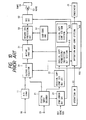
- FIG. 10 is a block diagram of this DAT.
- numeral 11 is an A/D converter.
- Numeral 21 is a digital input decoder for decoding a digital input signal, from a terminal 20, specified by a standard (IEC-958) of a digital audio interface to produce digital audio and sub-code signals.
- Numeral 22 is a digital copy control signal detection circuit for detecting a digital copy control signal included in the sub-code signal.
- Numeral 24 is a synchronizing error detection circuit for detecting errors in bit synchronizing or frame synchronizing.
- Numeral 30 is a record signal selector for selecting either output signal of the A/D converter 11 or an output signal of the digital input decoder 21.
- Numeral 31 is a muting processing circuit for muting the record signal.
- Numeral 400 is a system controlling section for controlling operation of the system.
- the system controlling section 400 comprises a microprocessor for controlling the whole system through communication through its input and output ports with peripheral circuits and logical calculation processing therein. As structure of the microprocessor (mpu) is well-known, thus, the detailed description is omitted.
- Fig. 11 shows a flow chart showing flows of controlling operation of the prior art DAT shown in Fig. 10.
- a program stored in the system controlling section 400 is provided such that the system controlling section 400 operates in accordance with the flow chart of Fig. 11.
- Numeral 410 included in the system controlling section 400 is a permission/inhibition determination section for making determination as to permission/inhibition of digital copying in accordance with the digital copy controlling and synchronizing error detection signals.
- Numeral 420 is a digital copying recording controlling signal generation section included in the system controlling section for generating a digital controlling signal to be recorded on the recording medium.
- Numeral 51 is a sub-code encoder for converting the digital copy controlling signal into a sub-code formatted signal.
- Numeral 50 is a record signal processing circuit for converting the audio digital and sub-code signals into a record format signal.
- Numeral 52 is a recording circuit.
- Numeral 53 is a head.
- Numeral 54 is a magnetic tape.
- Numeral 60 is a operation switch.
- Numeral 70 is an indicator.
- Fig. 11 shows a flow chart of controlling operation of the system controlling section 400.
- an operation mode controlling section 430 included in the system controlling section 400 controls the record signal selector 30 to select the digital input signal from the terminal 20.
- the mpu detects synchronizing condition and determines permission/inhibition digital copying. If the result shows "permission”, it causes the recording circuit 52 to be in recording condition (step 205) from the digital copy control signal. If the result shows "inhibition", it prevents the recording circuit 52 to be in the recording condition and indicates "digital copying is forbidden” and provides flickering indication to promote some counter operation (step 206).
- step 205 condition detection after it enters a digital copy recording mode (step 205) and operation thereof.
- mpu detects synchronizing error and digital copy controlling signal (steps 207 and 209). If synchronizing is not in error and the digital copy controlling signal indicates permission of copying, the mpu maintains the digital copy operation (step 211). If synchronizing is in error and the digital copy controlling signal indicates inhibition of copying, it controls the muting processing circuit 31 so that a muted signal is recorded (step 211).
- An error in synchronizing may occur because the receiving side cannot respond the change of the sampling frequency when a sampling frequency of the digital signal is changed. For example, when a satellite broadcasting signal is received directly, a synchronizing error occurs when the mode is changed between A and B. This is because sampling frequencies of A and B modes are different each other. Then, for the synchronizing error interval, the muted signal is recorded. Further, if the number of generations of copy permitted is specified and is recorded on a recording medium for protecting copyright, and when this magnetic tape is reproduced, the digital copying controlling signal may change from permission to inhibition of digital copying. Thus, if copying is carried out from such a magnetic tape to other magnetic tape, some portion of another magnetic tape includes muted portions so that the copied tape becomes different one from one that the operator intended to make. In other words, the recorded program is not in continuous.
- the operator can carry out digital copying if the operator acknowledges that the input signal is one permitted for digital copying.
- the operator does not know such information, once the operator tries to set digital copy mode and record so that he is informed of permission or inhibition of digital copying.
- an analog signal is available from the same source, which includes the same content as the digital audio signal includes, the analog signal is supplied to the analog signal input terminal 10 and then the apparatus is changed into analog recording mode in response to the operation switch 60. Then the content can be copied using the analog signal in stead of the digital signal. Further, if synchronizing becomes in error during digital copying or a control signal indicative of inhibition of digital copying occurs during digital copying, a muted signal is recorded and an alarm is displayed. In response to this, the operator temporally stops recording and then he changes the apparatus into the analog recording mode with the operation switch 60, so that he can copy the analog signal including the content as the same as the digital audio signal including.
- this invention provides data apparatus for maintaining copy operation even if a condition of digital input signal changes during digital copying.
- the present invention has been developed in order to remove the above-described drawbacks inherent to the conventional data recording apparatus.
- a data recording apparatus comprises a digital input processing circuit, an analog input processing circuit including an A/D converter for recording the analog input signal in a digital form, a switch for selecting either digital or analog input signal for recording, and a control circuit. Normally, the apparatus records the digital input signal.
- the digital input processing circuit detects a synchronizing error or inhibition of recording the digital input signal (digital copy) by analyzing the sub-code signal of the digital input signal, the control circuit control the switch so as to select the analog input signal.
- a polarity change circuit, variable delay, and variable gain amplifier are further provided.
- a first data recording apparatus comprising; an A/D converter for converting an analog input signal; a digital decoder for decoding a digital input signal to obtain digital data and a synchronizing signal; a selector responsive to a control signal for selecting either an output of the A/D converter or the digital data for recording; synchronizing error detector for detecting synchronizing error through comparison between the synchronizing signal and a reference synchronizing signal; and a controller responsive to an output of the synchronizing error detector for producing the control signal to cause the selector to select the output of the A/D converter when synchronizing error is detected.
- a second data recording apparatus comprising; an A/D converter for converting an analog input signal; a digital decoder for decoding digital input signal to obtain a digital data and a sub-code signal; a selector for selecting either an output of the A/D converter or the digital data in response to a control signal; a detector responsive to the sub-code signal for detecting a copy control signal indicative of permission and inhibition of recording with the digital input signal; and a controller responsive to the detected copy control signal for producing the control signal to cause the selecting means to select the output of the A/D converter when the inhibition is detected.
- a polarity changing circuit can be provided to the first and second apparatus to consist the polarity of the analog signal with that of the digital input signal.
- a variable delay circuit may be provided to the first and second apparatus to consist the phase of the analog signal with that of the digital input signal.
- a variable gain amplifier may be provided to the first and second apparatus to consist the amplitude of the analog signal with that of the digital input signal.
- a muting circuit may be provided to the first and second apparatus to mute the input signal when synchronizing error and inhibition of copy are detected respectively.
- Fig. 1 is a block diagram showing a first embodiment of the data recording apparatus of the invention.
- Fig. 2 shows a flow chart showing flows of controlling operation of the DAT shown in Fig. 1 of the embodiment of the invention.
- an analog audio input signal is applied to "a" input of an auxiliary input selector 85 through a terminal 10.
- Another analog audio input signal is also applied to "b" input of the input selector 85 through a terminal 90.
- the auxiliary input selector 85 selects either analog audio signals in response to a system controlling section 40.
- An output of the auxiliary input selector 85 is sent to an A/D converter 11.
- An output signal of the digital input decoder 21, i.e., sub-code data is sent to a digital copy control signal detection circuit 22 for detecting a digital copy control signal included in the sub-code signal.
- the synchronizing signal is sent to a synchronizing error detection circuit 24 for detecting errors in bit synchronizing or frame synchronizing by comparison between said synchronizing signal and a reference synchronizing signal.
- An output of the A/D converter 11 is sent to "d" input of a record signal selector 30 through a polarity changing circuit 81 mentioned latter. Another input “c” of the record signal selector 30 is supplied with an output of the digital input decoder.
- the record signal selector 30 selects either the output signal of the A/D converter 11 or the output signal of the digital input decoder 21, i.e., digital data.
- An output signal of the record signal selector 30 is recorded on a magnetic tape 54 through a record signal processing circuit 50 for formatting the audio digital signal for recording together with sub-code from a sub-code encoder 51, through a recording circuit 52, and through a head 53.
- the digital copy control signal detected by the digital copy control signal detection circuit 22 is sent to a system controlling section 400.
- the polarity changing circuit 81 changes polarity of the output signal of the A/D converter 11. It changes polarity relation between the output of the A/D converter 11 and the digital data.
- Numeral 84 is a signal correlation detection circuit for detection difference between the output of A/D converter and the digital data in polarity, magnitude, and phase for generating a polarity control signal 841 and correlation detection signal 844.
- the system controlling section 40 comprises a microprocessor (mpu) for controlling the whole system through communication through its input and output ports with peripheral circuits and logical calculation processing therein.
- a microprocessor mpu
- Fig. 2 shows a flow chart showing flows of controlling operation of the first embodiment which is common to embodiments through the specification.
- a program stored in the system controlling section 40 is provided such that the system controlling section 40 operates in accordance with the flow chart of Fig. 2.
- Numeral 41 included in the system controlling section 40 is a permission/inhibition determination section for making determination as to permission/inhibition of digital copying in accordance with the digital copy controlling and synchronizing error detection signals.
- Numeral 42 is a digital copying recording controlling signal generation section included in the system controlling section for generating a digital controlling signal to be recorded on the recording medium.
- Numeral 51 is a sub-code encoder for converting the digital copy controlling signal into a sub-code formatted signal. Actually, the mpu executes a program of flow chart in Fig. 2 for performing functions of the digital copy permission/inhibition determination section 41; digital copy recording control signal generation section 42, and the operation mode controlling section 43.
- Numeral 60 is a operation switch.
- Numeral 70 is an indicator.
- the system controlling section 40 When an operator sets the apparatus to be in the digital copy mode with the operation switch 60 (step 102), the system controlling section 40 sends a control signal to the auxiliary input selector 85 so that the auxiliary input selector 85 selects a signal coming from the auxiliary analog input terminal 90 (step 121). Moreover, the system controlling section 40 controls the record signal selector 30 to select the digital input signal (step 121). Then, the system controlling section 40 detects outputs of the digital copy control signal detection circuit 22 and the synchronizing error detection circuit 24 (step 103) to determine synchronizing condition and permission/inhibition of digital copying (step 104). If the answer is "permission", the system controlling section 40 turns the recording circuits into recording condition (step 105).
- step 122 the system controlling section 40 checks an output of the signal correlation detection circuit 84 to detect correlation (step 123). If there is correlation, it controls the recording signal selector 30 to change signal selection from the digital input to the analog input signal. Thus, the signal being recorded is switched to the signal from the auxiliary analog input terminal 90 (step 112). In addition to this operation, indications of substitution recording is executed in step 112, as well as information whether there is synchronizing error or not and digital copying is permitted or inhibited is made by the indicator 70 to arouse the operator's attention. Therefore, even if the apparatus is set to the digital copying mode, it can record the input signal coming from the auxiliary analog input terminal 90, converted into a digital signal by through the A/D converter 11.
- Fig. 3 shows interconnection between this apparatus and an external apparatus, which is suited for embodiments throughout the specification.
- numeral 1a, 1b, 1c, 1d, or 1e is a DAT.
- Numeral 4 is a CD player.
- Numeral 410 is an analog signal output terminal.
- Numeral 420 is a digital signal output terminal.
- the DAT is connected to the CD player, as shown in Fig. 3.
- both the auxiliary analog input terminal 90 and the digital signal input terminal 20 are supplied with a reproduction signal of the same CD player. Therefore, when synchronizing error or inhibition of digital copy occurs, the apparatus detects synchronizing error and inhibition of digital copy and thus, it can record the analog signal automatically in replace with the digital signal.
- the apparatus After starting recording (step 105) with the digital input selected, the apparatus executes detection of synchronizing error and of digital copy control signal ( steps 107 and 109). If synchronizing is in not error and the digital copy control signal indicates permission of copy, the apparatus maintains digital copying operation (step 111). If synchronizing is in error or the digital copy control signal indicates inhibition of digital copy (step 108), processing proceeds to step 122 where correlation is determined with the output of the signal correlation detection circuit 84 (step 123). If there is correlation, the system controlling section 40 controls the recording signal selector 30 to change signal selection from the digital input to the analog input. Even though once the apparatus is in digital copy mode, the apparatus can record the signal inputted to the auxiliary analog input terminal 90 converted into digital signal by the A/D converter 11. If the apparatus is interconnected as shown in Fig. 3 and when synchronizing error or inhibition of copy during recording the digital signal, it can record the analog signal in stead of the digital input signal automatically in response to detecting such conditions.
- analog input recording of step 112 is included in the loop of detecting the condition of the digital input decoder, so that when synchronising error is recovered or inhibition is cancelled, the apparatus can return to the original state, i.e., the digital input recording condition (step 111).
- this technique is different from the original analog input selection recording (step 113).
- the apparatus can returns automatically to the digital copying operation whose sound quality is not deteriorated.
- the whole content of the program can be recorded though the digital control signal turns into inhibition of digital copying during recording when using the audio signal from a magnetic tape where the number of generations of possible digital copying is specified.
- step 112 it is possible to indicate of impossibility of digital copy and to further indicate whether synchronizing error or inhibition digital copying causes the impossibility.
- the operator can know the condition from these indications, so that the indication promotes a recovering operation against the trouble when synchronization error occurs.
- Fig. 4 is a block diagram of the polarity changing circuit 81.
- the polarity changing circuit 81 comprises n EXCLUSIVE OR gates 81-1 to 81-n whose one inputs are supplied with the output of the A/D converter 11 respectively, as shown in Fig. 4. Another inputs of the EXCLUSIVE OR gates are supplied with the polarity control signal 841 from the signal correlation detection circuit 84. The output of the EXCLUSIVE OR gates 81-1 to 81-n are sent sto the record signal selector 30. Therefore, the polarity changing circuit changes polarity of the output of the A/D converter 11 in response to the polarity signal from the signal correlation detection circuit 84.
- Fig. 5A is a block diagram of the signal correlation circuit 84.
- the output 845 of the polarity changing circuit 81 is applied to a peak detector circuit 89a.
- the output of the digital input decoder is applied to another peak detector 89b.
- the most significant bit MSB of the output 845 is also applied to one input of an EXCLUSIVE OR gate 85 of a circuit 84a.
- Another input of the EXCLUSIVE OR gate 85 is supplied with the MSB of the output 846.
- An output of the EXCLUSIVE OR 85 is sent to an integrator 86.
- An output of the integrator 86 is supplied to comparators 87 and 88.
- the comparators 87 and 88 are supplied with reference signals REF1 and REF2 respectively.
- One output 841 of the circuit 84a i.e., the polarity signal from the comparator 87 detects consistency of polarity between the outputs 845 and 846.
- the polarity changing circuit 81 changes polarity of its output signal in response to the polarity signal 841 to consist polarity of its output with the output of the digital decoder 21.
- another output 844 of the circuit 84a from the comparator 88 shows correlation between the outputs 845 and 846. This is because if there is correlation of opposite polarity between outputs 845 and 846, at first, the comparator detects polarity difference and the polarity changing circuit 81 changes its polarity.
- the comparator 88 can detect whether there is correlation between the outputs 845 and 846 or there is no correlation. If there is correlation of the same polarity between outputs 845 and 846, the comparator 88 can detect whether signal correlation exist or not at once. However, there are many techniques for detecting signal correlation and it is possible to detect correlation of the same polarity and the opposite polarity at once.
- the peak detector 89a detects peak time and peak value of the output 845 to produce a peak time pulse and peak data respectively.
- the peak detector 89b detects peak time and peak value of the output 846 to produce a peak time pulse and peak data respectively.
- the peak time pulses are applied to a time difference detector 91 which detects time difference between peaks of the outputs 845 and 846.
- Fig. 5B shows a block diagram of the peak detectors 89a and 89b. In Fig. 5B, output 845 or 846 is supplied to n EXCLUSIVE OR gates 94 as shown, which detects an absolute value. The absolute value is sent to inputs of digital comparator 96 and D latch array 95.
- FIG. 5C is a block diagram of the time difference detector 91.
- the peak time pulse from the peak detector 89a is applied to a reset input of a counter 97 whose clock pulse input is supplied with a clock CLK2.
- the counter starts counting in response to the peak time pulse of the peak detector 89a.
- An output of the counter 97 is sent to a D latch 99 whose clock pulse input is supplied with the peak time pulse from the peak time detector 89b.
- a Q output of the D latch 99 holds a data of the output of the counter 97 in response to the peak time pulse from the peak detector 89a. This data shows time difference between the peaks of the outputs 845 and 846.
- the signal correlation signal 844 shows the signal correlation between the analog signal and the digital input signal correctly after the polarity control signal 841 is produced.
- the mpu 40 detects the signal correlation signal with a delay time after switching the record signal selector 30.
- Fig. 6 is a block diagram showing the second embodiment of the invention.
- Fig. 2 shows a flow chart showing controlling operation of the second embodiment also.
- the basic structure of the second embodiment of Fig.6 is the same as that of the first embodiment.
- Different points are that a variable delay circuit 82 is provided between the A/D converter 11 and the record signal selector 30, a delay circuit 182 is provided between the digital input decoder 21 and the record signal selector 30, and the polarity changing circuit 81 is omitted. Therefore, a detailed description will be omitted and different points are described mainly.
- the variable delay circuit 82 delays the signal from the analog input by a delay time determined by the delay control signal 842.
- the delay circuit 182 delays the digital audio signal from the digital decoder 21 by a given delay time. Operation of digital copying of the data recording apparatus structured as mentioned above will be described, particularly, operation of the variable delay circuit 82 will be described mainly, which is a different point from the first embodiment.
- the signal correlation detection circuit 84 detects, for a given interval, time difference between an instance when the output signal of the A/D converter 11 reaches a peak value in amplitude and another instance when the output signal of the digital input decoder 21 reaches a peak value in amplitude.
- the signal correlation detection circuit 84 sends a delay control signal 842 to the variable delay circuit 82 in accordance with the detection signal. That is, it control a delay time of the output signal of the A/D converter 11 such that both the signal of the A/D converter 11 and the output signal of delay circuit 182 reaches the record signal selection circuit 30 at the same instance. Therefore, the unnatural variation in the output level of the record signal selection circuit 30 due to change of signal selection can be reduced.
- the delay circuit 182 is provided in the digital input signal line and the variable delay circuit 82 is provided in the output line of the A/D converter 11 to control delay time for time-adjusting between the digital and analog input signals.
- the variable delay circuit 82 may be provided between the A/D converter 11 and the record signal selector 30.
- the delay amount of the variable delay circuit 82 is set to the max by the delay control signal 842 to prevent that the analog audio signal reach to the record signal selector 30 earlier than the digital audio signal.
- Fig. 7 is a block diagram showing the third embodiment of the invention of data recording apparatus.
- Fig. 2 shows a flow chart shoring controlling operation of the third embodiment of Fig. 7 also.
- the basic structure of the third embodiment of Fig. 7 is the same as that of the first embodiment.
- Different points are a variable gain amplifier 83 is provided between the input terminal 90 and the input selector 85 and the polarity changing circuit 81 is omitted. Therefore, a detailed description will be omitted and different points are described mainly.
- the variable gain amplifier 83 changes gain for the analog input signal in accordance with a gain control signal 843.
- the signal correlation detection circuit 84 detects peak values of the output signal of the A/D converter 11 and the output signal of the digital input decoder 21 for a given interval and compares them and detects deference in amplitude of these signals.
- the signal correlation detection circuit 84 sends a gain control signal 843 to the variable gain amplifier 83 in accordance with the detection result. That is, it control amplitude of the log input signal such that amplitudes of the output signal of the A/D converter 11 is made substantially equal to that of the output signal of digital signal decoder 21. Therefore, the unnatural variation in the output level of the record signal selector 30 due to change of signal selection can be reduced.
- Fig. 8 is a block diagram showing the fourth embodiment of the invention of data recording apparatus.
- Fig. 2 shows a flow chart showing controlling operation of the fourth embodiment of Fig. 8.
- the basic structure of the fourth embodiment of Fig. 8 is the same as that of the first embodiment. Different points are that a variable delay circuit 82 and variable gain amplifier 83 are provided. Therefore, a detailed description will be omitted. Operation of digital copying of the data recording apparatus structured as mentioned above will be described.
- the fourth embodiment in order to increase signal correlation, there are provided the polarity changing circuit 81, variable delay circuit 82 and variable gain circuit 83.
- the signal correlation detection circuit 84 supplies polarity control signal 841, delay control signal 842, and gain control signal 843 to control adaptively these circuits.
- Fig. 9 is a block diagram showing the fifth embodiment of the invention of data recording apparatus.
- Fig. 2 shows a flow chart showing controlling operation of the fifth embodiment of Fig. 9 also.
- the basic structure of the fifth embodiment of Fig. 9 is the same as that of the fourth embodiment.
- a different point is that a muting circuit 31 are provided. Therefore, a detailed description will be omitted.
- the muting circuit 31 replaces the record signal with a muted signal in accordance with the control signal of the system control circuit 40. Operation different from other embodiments of the data recording apparatus as structured as mentioned above for digital copy will be described.
- step 122 these system control circuit 40 checks the output of the signal correlation detection circuit 84 (step 123). If it judges the output as not in correlation, it controls the muting circuit 31 so that a muted signal is recorded (step 124). That is, if the signal inputted into the auxiliary analog signal input terminal 90 is different from that inputted into the digital signal input terminal 20, it controls the muting circuit 31 to record the muted signal during these signals being inconsistent with each other. Thus, a problem that a desired program is recorded on the magnetic tape 54 with other program mixed together.
- step 124 in addition to this, an indication showing muted signal being recorded is made to show that substitution recording with the analog signal is not permitted or there is a problem. The operator can tray again recording or can check digital signal lines or the auxiliary analog input lines. Thus, if there is no correlation, such error condition is indicated as well as a problem that a desired program is recorded with other program mixed.
- the operation mode controlling circuit 43 receives a result from the digital copy permission/forbidden detection circuit 41 and sends it to the digital copy control signal for recording generation circuit 42. Then the result is converted into a sub-cord format data by the sub-code encoder 51 to supply it to the record signal processing circuit 50.
- the record signal processing circuit 50 produces a record signal using the main data together with the sub-cord data in accordance with a record format.
- the record signal is recorded by the head 53 on the magnetic tape through the recording circuit. Therefore, when the recorded tape is reproduced it is possible to distinguish the portion where analog signal is recorded from another portion where digital signal is recorded. This can be utilized for indication.
- Such indication provides the operator history of the magnetic tape with respect to copying, so that it gives the operator useful information for operating and maintenance of the system and it removes an feeling of uneasiness and a suspicion during operation.
- the system controlling is carried out using both data of the synchronizing error detection from the digital input decoder 21 and copying inhibition bit from the digital copy control signal detection circuit 22.
- data from the synchronizing error detection circuit or from the digital copy control signal detection circuit 22 can be used for controlling, as clearly shown from the above-mentioned description. Each data occurs separately and has each function and effect.
- This invention is not limited to a scope of the DAT, but is widely applicable to data recording apparatus for being capable of recording either analog or digital signal, for example, digital video tape recorder, AV disc recorder, or digital solid-state memory recorder, etc.
Landscapes
- Engineering & Computer Science (AREA)
- Signal Processing (AREA)
- Computer Security & Cryptography (AREA)
- Multimedia (AREA)
- Signal Processing For Digital Recording And Reproducing (AREA)
Applications Claiming Priority (4)
| Application Number | Priority Date | Filing Date | Title |
|---|---|---|---|
| JP1233233A JP2629372B2 (ja) | 1989-09-08 | 1989-09-08 | 情報記録装置 |
| JP233233/89 | 1989-09-08 | ||
| JP1238525A JP2584067B2 (ja) | 1989-09-14 | 1989-09-14 | 情報記録装置 |
| JP238525/89 | 1989-09-14 |
Publications (3)
| Publication Number | Publication Date |
|---|---|
| EP0416663A2 true EP0416663A2 (de) | 1991-03-13 |
| EP0416663A3 EP0416663A3 (en) | 1992-02-26 |
| EP0416663B1 EP0416663B1 (de) | 1998-02-11 |
Family
ID=26530931
Family Applications (1)
| Application Number | Title | Priority Date | Filing Date |
|---|---|---|---|
| EP90117393A Expired - Lifetime EP0416663B1 (de) | 1989-09-08 | 1990-09-10 | Daten-Aufzeichnungsgerät |
Country Status (4)
| Country | Link |
|---|---|
| US (1) | US5159502A (de) |
| EP (1) | EP0416663B1 (de) |
| KR (1) | KR940008688B1 (de) |
| DE (1) | DE69032036T2 (de) |
Cited By (7)
| Publication number | Priority date | Publication date | Assignee | Title |
|---|---|---|---|---|
| EP0501792A3 (en) * | 1991-02-28 | 1993-01-20 | Sony Corporation | Digital signal recording apparatus for analog/digital input |
| WO1994022266A3 (en) * | 1993-03-18 | 1995-01-19 | Macrovision Corp | Copy protection for hybrid digital video tape recording and unprotected source material |
| EP0624978A3 (de) * | 1993-05-14 | 1995-04-05 | Matsushita Electric Industrial Co Ltd | Gerät zum Aufzeichnen und Wiedergeben von digitalen Daten. |
| EP0511633A3 (de) * | 1991-04-30 | 1995-04-12 | Sharp Kk | |
| EP0866462A3 (de) * | 1993-06-16 | 1999-02-03 | Pioneer Electronic Corporation | Tonsignalaufzeichnungsgerät mit Indexnummernsignalerzeugungsfunktion |
| EP0899733A1 (de) * | 1997-08-28 | 1999-03-03 | Sony DADC Austria AG | System zur Kopierverwaltung einer optischen Platte |
| FR2783658A1 (fr) * | 1998-09-23 | 2000-03-24 | Thomson Multimedia Sa | Protection contre la copie de donnees numeriques stockees sur un support d'informations |
Families Citing this family (10)
| Publication number | Priority date | Publication date | Assignee | Title |
|---|---|---|---|---|
| US6449109B1 (en) * | 1989-06-07 | 2002-09-10 | Canon Kabushiki Kaisha | Recording and reproducing apparatus |
| US5907443A (en) * | 1990-05-30 | 1999-05-25 | Canon Kabushiki Kaisha | Recording and reproducing apparatus adapted to selectively control the number of copies made |
| JP3128328B2 (ja) * | 1992-05-26 | 2001-01-29 | キヤノン株式会社 | 記録装置 |
| US5748763A (en) | 1993-11-18 | 1998-05-05 | Digimarc Corporation | Image steganography system featuring perceptually adaptive and globally scalable signal embedding |
| JP3371659B2 (ja) * | 1995-12-28 | 2003-01-27 | ソニー株式会社 | 記録装置及び制御方法 |
| JPH10247855A (ja) * | 1997-03-04 | 1998-09-14 | Sony Corp | 放送信号受信装置 |
| DE69932695T2 (de) * | 1998-12-11 | 2007-09-13 | Sony Corp. | Technik zur Datenkopiersteuerung |
| TW566041B (en) * | 2001-07-06 | 2003-12-11 | Hitachi Ltd | Digital data recording device and output device |
| US20090252204A1 (en) * | 2008-04-04 | 2009-10-08 | Delphi Technologies, Inc. | Receiver system for receiving analog and digital signals |
| JP6378591B2 (ja) | 2014-09-16 | 2018-08-22 | キヤノン株式会社 | 記録媒体の種類を判別する判別装置および画像形成装置 |
Family Cites Families (7)
| Publication number | Priority date | Publication date | Assignee | Title |
|---|---|---|---|---|
| NL8500515A (nl) * | 1985-02-22 | 1986-09-16 | Arie Marinus Wijnen | Werkwijze en toestel voor het beveiligen van beeldsignalen. |
| JPH0743825B2 (ja) * | 1985-12-04 | 1995-05-15 | ソニー株式会社 | ダビング方式 |
| JPS62167673A (ja) * | 1986-01-20 | 1987-07-24 | Sanyo Electric Co Ltd | デジタルオ−デイオ記録装置 |
| EP0297242B1 (de) * | 1987-06-30 | 1994-07-06 | Kabushiki Kaisha Toshiba | System und Verfahren zur Aufnahme/Wiedergabe mit Aufnahmebeschränkungsfunktion |
| US4839733A (en) * | 1987-12-15 | 1989-06-13 | Karamon John J | Method and system for synchronization of an auxiliary sound source to motion picture film, video tape, or other picture source containing a sound track |
| US5057947A (en) * | 1988-02-10 | 1991-10-15 | Matsushita Electric Industrial Co., Ltd. | Recording and reproducing apparatus with limited digital copying |
| US4945014A (en) * | 1988-02-10 | 1990-07-31 | Mitsubishi Petrochemical Co., Ltd. | Secondary battery |
-
1990
- 1990-09-07 KR KR1019900014168A patent/KR940008688B1/ko not_active Expired - Fee Related
- 1990-09-07 US US07/578,917 patent/US5159502A/en not_active Expired - Fee Related
- 1990-09-10 DE DE69032036T patent/DE69032036T2/de not_active Expired - Fee Related
- 1990-09-10 EP EP90117393A patent/EP0416663B1/de not_active Expired - Lifetime
Cited By (12)
| Publication number | Priority date | Publication date | Assignee | Title |
|---|---|---|---|---|
| EP0501792A3 (en) * | 1991-02-28 | 1993-01-20 | Sony Corporation | Digital signal recording apparatus for analog/digital input |
| US5295023A (en) * | 1991-02-28 | 1994-03-15 | Sony Corporation | Digital signal recording apparatus for analog/digital input |
| EP0511633A3 (de) * | 1991-04-30 | 1995-04-12 | Sharp Kk | |
| WO1994022266A3 (en) * | 1993-03-18 | 1995-01-19 | Macrovision Corp | Copy protection for hybrid digital video tape recording and unprotected source material |
| EP0624978A3 (de) * | 1993-05-14 | 1995-04-05 | Matsushita Electric Industrial Co Ltd | Gerät zum Aufzeichnen und Wiedergeben von digitalen Daten. |
| US5543937A (en) * | 1993-05-14 | 1996-08-06 | Matsushita Electric Industrial Co. Ltd. | Apparatus for recording and playing back digital data |
| EP0866462A3 (de) * | 1993-06-16 | 1999-02-03 | Pioneer Electronic Corporation | Tonsignalaufzeichnungsgerät mit Indexnummernsignalerzeugungsfunktion |
| EP0899733A1 (de) * | 1997-08-28 | 1999-03-03 | Sony DADC Austria AG | System zur Kopierverwaltung einer optischen Platte |
| US6535858B1 (en) | 1997-08-28 | 2003-03-18 | Sony Dadc Austria Ag | Optical disc copy management system |
| FR2783658A1 (fr) * | 1998-09-23 | 2000-03-24 | Thomson Multimedia Sa | Protection contre la copie de donnees numeriques stockees sur un support d'informations |
| WO2000017871A1 (fr) * | 1998-09-23 | 2000-03-30 | Thomson Multimedia | Protection contre la copie de donnees numeriques stockees sur un support d'informations |
| US7631358B1 (en) | 1998-09-23 | 2009-12-08 | Thomson Licensing | Copy protection method for digital data stored on a medium |
Also Published As
| Publication number | Publication date |
|---|---|
| EP0416663B1 (de) | 1998-02-11 |
| DE69032036D1 (de) | 1998-03-19 |
| EP0416663A3 (en) | 1992-02-26 |
| KR910006956A (ko) | 1991-04-30 |
| DE69032036T2 (de) | 1998-08-20 |
| US5159502A (en) | 1992-10-27 |
| KR940008688B1 (ko) | 1994-09-24 |
Similar Documents
| Publication | Publication Date | Title |
|---|---|---|
| EP0416663A2 (de) | Daten-Aufzeichnungsgerät | |
| US5130864A (en) | Digital recording and reproducing apparatus or digital recording apparatus | |
| JPH0654289A (ja) | 映像信号記録装置及び再生装置 | |
| EP0584727B1 (de) | Automatische Phaseneinstellungsschaltung für ein Taktsignal | |
| JP2584067B2 (ja) | 情報記録装置 | |
| US5295023A (en) | Digital signal recording apparatus for analog/digital input | |
| JPS58139310A (ja) | ミユ−ト回路 | |
| US5532831A (en) | Recording apparatus and method for a high definition video cassette recorder | |
| JPS6139982A (ja) | デイスク再生装置のアドレスデ−タ処理方式 | |
| JP2629381B2 (ja) | デジタル記録再生装置 | |
| JP2931019B2 (ja) | デジタルテープレコーダの曲間検出方式 | |
| JP2944131B2 (ja) | ビデオ記録再生装置 | |
| JP2629372B2 (ja) | 情報記録装置 | |
| JP3293503B2 (ja) | 記録再生装置 | |
| JPS6329349B2 (de) | ||
| US4860129A (en) | Signal reproducing device | |
| JP3416340B2 (ja) | ビデオテープレコーダ | |
| US5535065A (en) | Recording and reproducing apparatus having means for performing diagnostic functions | |
| KR100303091B1 (ko) | 디지털비디오카세트레코더의녹화상태판별장치및방법 | |
| JP3089978B2 (ja) | 垂直同期信号挿入装置 | |
| JP2735624B2 (ja) | デイジタル音声記録再生装置 | |
| JP2517429B2 (ja) | 音多モ―ド判別回路 | |
| JP2737383B2 (ja) | 磁気記録再生装置 | |
| JPS63207220A (ja) | 自動位相補正装置 | |
| JPH0520826B2 (de) |
Legal Events
| Date | Code | Title | Description |
|---|---|---|---|
| PUAI | Public reference made under article 153(3) epc to a published international application that has entered the european phase |
Free format text: ORIGINAL CODE: 0009012 |
|
| 17P | Request for examination filed |
Effective date: 19900910 |
|
| AK | Designated contracting states |
Kind code of ref document: A2 Designated state(s): DE FR GB |
|
| PUAL | Search report despatched |
Free format text: ORIGINAL CODE: 0009013 |
|
| AK | Designated contracting states |
Kind code of ref document: A3 Designated state(s): DE FR GB |
|
| 17Q | First examination report despatched |
Effective date: 19940812 |
|
| GRAG | Despatch of communication of intention to grant |
Free format text: ORIGINAL CODE: EPIDOS AGRA |
|
| GRAG | Despatch of communication of intention to grant |
Free format text: ORIGINAL CODE: EPIDOS AGRA |
|
| GRAH | Despatch of communication of intention to grant a patent |
Free format text: ORIGINAL CODE: EPIDOS IGRA |
|
| GRAH | Despatch of communication of intention to grant a patent |
Free format text: ORIGINAL CODE: EPIDOS IGRA |
|
| GRAA | (expected) grant |
Free format text: ORIGINAL CODE: 0009210 |
|
| AK | Designated contracting states |
Kind code of ref document: B1 Designated state(s): DE FR GB |
|
| REF | Corresponds to: |
Ref document number: 69032036 Country of ref document: DE Date of ref document: 19980319 |
|
| ET | Fr: translation filed | ||
| PLBE | No opposition filed within time limit |
Free format text: ORIGINAL CODE: 0009261 |
|
| STAA | Information on the status of an ep patent application or granted ep patent |
Free format text: STATUS: NO OPPOSITION FILED WITHIN TIME LIMIT |
|
| 26N | No opposition filed | ||
| REG | Reference to a national code |
Ref country code: GB Ref legal event code: IF02 |
|
| PGFP | Annual fee paid to national office [announced via postgrant information from national office to epo] |
Ref country code: FR Payment date: 20050823 Year of fee payment: 16 |
|
| PGFP | Annual fee paid to national office [announced via postgrant information from national office to epo] |
Ref country code: GB Payment date: 20050907 Year of fee payment: 16 |
|
| PGFP | Annual fee paid to national office [announced via postgrant information from national office to epo] |
Ref country code: DE Payment date: 20050909 Year of fee payment: 16 |
|
| PG25 | Lapsed in a contracting state [announced via postgrant information from national office to epo] |
Ref country code: DE Free format text: LAPSE BECAUSE OF NON-PAYMENT OF DUE FEES Effective date: 20070403 |
|
| GBPC | Gb: european patent ceased through non-payment of renewal fee |
Effective date: 20060910 |
|
| REG | Reference to a national code |
Ref country code: FR Ref legal event code: ST Effective date: 20070531 |
|
| PG25 | Lapsed in a contracting state [announced via postgrant information from national office to epo] |
Ref country code: GB Free format text: LAPSE BECAUSE OF NON-PAYMENT OF DUE FEES Effective date: 20060910 |
|
| PG25 | Lapsed in a contracting state [announced via postgrant information from national office to epo] |
Ref country code: FR Free format text: LAPSE BECAUSE OF NON-PAYMENT OF DUE FEES Effective date: 20061002 |