EP0416733B1 - Echangeur de chaleur - Google Patents
Echangeur de chaleur Download PDFInfo
- Publication number
- EP0416733B1 EP0416733B1 EP90308036A EP90308036A EP0416733B1 EP 0416733 B1 EP0416733 B1 EP 0416733B1 EP 90308036 A EP90308036 A EP 90308036A EP 90308036 A EP90308036 A EP 90308036A EP 0416733 B1 EP0416733 B1 EP 0416733B1
- Authority
- EP
- European Patent Office
- Prior art keywords
- manifold
- tubes
- heat exchanger
- tube
- ports
- Prior art date
- Legal status (The legal status is an assumption and is not a legal conclusion. Google has not performed a legal analysis and makes no representation as to the accuracy of the status listed.)
- Expired - Lifetime
Links
- 239000012530 fluid Substances 0.000 claims abstract description 17
- 239000000463 material Substances 0.000 claims abstract description 5
- 230000001939 inductive effect Effects 0.000 claims 1
- 239000012815 thermoplastic material Substances 0.000 claims 1
- 239000002023 wood Substances 0.000 abstract description 3
- XLYOFNOQVPJJNP-UHFFFAOYSA-N water Substances O XLYOFNOQVPJJNP-UHFFFAOYSA-N 0.000 description 11
- 238000010438 heat treatment Methods 0.000 description 8
- RYGMFSIKBFXOCR-UHFFFAOYSA-N Copper Chemical compound [Cu] RYGMFSIKBFXOCR-UHFFFAOYSA-N 0.000 description 7
- 229910052802 copper Inorganic materials 0.000 description 7
- 239000010949 copper Substances 0.000 description 7
- 229920001169 thermoplastic Polymers 0.000 description 6
- 239000004416 thermosoftening plastic Substances 0.000 description 6
- 229920002943 EPDM rubber Polymers 0.000 description 4
- 238000010276 construction Methods 0.000 description 4
- 238000009434 installation Methods 0.000 description 4
- 238000012546 transfer Methods 0.000 description 4
- 230000008602 contraction Effects 0.000 description 3
- 238000000034 method Methods 0.000 description 3
- 229920003023 plastic Polymers 0.000 description 3
- 239000004033 plastic Substances 0.000 description 3
- 230000004323 axial length Effects 0.000 description 2
- 230000006835 compression Effects 0.000 description 2
- 238000007906 compression Methods 0.000 description 2
- 238000005336 cracking Methods 0.000 description 2
- 239000013536 elastomeric material Substances 0.000 description 2
- 238000009413 insulation Methods 0.000 description 2
- 239000002184 metal Substances 0.000 description 2
- 229910052751 metal Inorganic materials 0.000 description 2
- 210000002445 nipple Anatomy 0.000 description 2
- 238000013021 overheating Methods 0.000 description 2
- 239000004800 polyvinyl chloride Substances 0.000 description 2
- 229920000915 polyvinyl chloride Polymers 0.000 description 2
- 239000004576 sand Substances 0.000 description 2
- 238000012935 Averaging Methods 0.000 description 1
- 239000003513 alkali Substances 0.000 description 1
- 238000006243 chemical reaction Methods 0.000 description 1
- 230000007797 corrosion Effects 0.000 description 1
- 238000005260 corrosion Methods 0.000 description 1
- 238000013461 design Methods 0.000 description 1
- 238000001125 extrusion Methods 0.000 description 1
- 230000008014 freezing Effects 0.000 description 1
- 238000007710 freezing Methods 0.000 description 1
- 239000013529 heat transfer fluid Substances 0.000 description 1
- 239000007788 liquid Substances 0.000 description 1
- 239000013521 mastic Substances 0.000 description 1
- 239000011159 matrix material Substances 0.000 description 1
- 230000000149 penetrating effect Effects 0.000 description 1
- 230000000135 prohibitive effect Effects 0.000 description 1
- 230000005855 radiation Effects 0.000 description 1
- 238000000926 separation method Methods 0.000 description 1
- 229910000679 solder Inorganic materials 0.000 description 1
- 239000007787 solid Substances 0.000 description 1
- 229920003051 synthetic elastomer Polymers 0.000 description 1
- 239000005061 synthetic rubber Substances 0.000 description 1
Images


Classifications
-
- F—MECHANICAL ENGINEERING; LIGHTING; HEATING; WEAPONS; BLASTING
- F24—HEATING; RANGES; VENTILATING
- F24D—DOMESTIC- OR SPACE-HEATING SYSTEMS, e.g. CENTRAL HEATING SYSTEMS; DOMESTIC HOT-WATER SUPPLY SYSTEMS; ELEMENTS OR COMPONENTS THEREFOR
- F24D3/00—Hot-water central heating systems
- F24D3/12—Tube and panel arrangements for ceiling, wall, or underfloor heating
- F24D3/14—Tube and panel arrangements for ceiling, wall, or underfloor heating incorporated in a ceiling, wall or floor
- F24D3/146—Tubes specially adapted for underfloor heating
-
- Y—GENERAL TAGGING OF NEW TECHNOLOGICAL DEVELOPMENTS; GENERAL TAGGING OF CROSS-SECTIONAL TECHNOLOGIES SPANNING OVER SEVERAL SECTIONS OF THE IPC; TECHNICAL SUBJECTS COVERED BY FORMER USPC CROSS-REFERENCE ART COLLECTIONS [XRACs] AND DIGESTS
- Y02—TECHNOLOGIES OR APPLICATIONS FOR MITIGATION OR ADAPTATION AGAINST CLIMATE CHANGE
- Y02B—CLIMATE CHANGE MITIGATION TECHNOLOGIES RELATED TO BUILDINGS, e.g. HOUSING, HOUSE APPLIANCES OR RELATED END-USER APPLICATIONS
- Y02B30/00—Energy efficient heating, ventilation or air conditioning [HVAC]
Definitions
- This invention relates to a heat exchanger, and more particularly, to a heat exchanger for conveying a heat containing fluid material in counter current pattern, and which can be installed in a wood or concrete floor and used to heat the floor and the earth space associated with the floor.
- Radiant heating systems such as those used in heat concrete or wood floors of residential and commercial buildings typically employ copper hot water conveying pipe embedded within a concrete slab, or in sand beneath the slab thereby providing additional thermal mass. Heated water is circulated through the pipes to transfer thermal energy from the water to the concrete or sand, and in turn heat the space above the slab by radiation.
- Heat transfer systems using copper pipe have several serious shortcomings. They are subject to corrosion, particularly by alkali in the concrete. The thermal expansion and contraction of the pipes together with the shifting and cracking of the concrete impose stresses which can cause leaks in the pipe. Those leaks are virtually impossible to repair without tearing up the floor.
- thermoplastic pipe such as rigid or semi-flexible polyvinyl chloride pipe.
- Thermal expansion and contraction of the thermoplastic pipe is low. Since pipe can be expanded if necessary, freezing water which expands on becoming frozen cannot cause ruptures to the pipe.
- the elastic properties of the thermoplastic pipe also make it more resistant to damage caused by shifting or cracking of the concrete floor.
- the thermoplastic tubular system is low in initial cost and is particularly advantageous for efficient low-temperature heat transfer.
- Bourne in U.S. Patent No. 4,782,889 discloses a low mass hydronic radiant floor heating system which includes a metal deck which has regularly spaced troughs therein. Tubing is placed in the troughs to distribute heat by circulating warm liquid through the tubing. In this arrangement the tubing is not embedded in the concrete.
- Zinn et al. discloses a heat exchanger in the form of a mat having a plurality of fluid conducting tubes arranged parallel to one another and joined by connecting webs. More particularly, Zinn et al. disclose a heat exchanger for radiant floor use having a plurality of parallel fluid-conducting tubes of elastomeric material formed in an elongated mat with flexible webs connecting adjacent pairs of tubes. Opposite end portions of all of the tubes remote from the central mat section are free of the webs and are connected to respective hollow manifolds through respective holes in the manifold walls.
- the tubes or mats are formed by an integral extrusion of elastomeric material such as synthetic rubber and particularly EPDM (polymerized ethylene propylene diene monomer or terpolymer).
- EPDM polymerized ethylene propylene diene monomer or terpolymer
- the invention pertains to a heat exchanger for conveying a heat containing fluid material in counter flow pattern
- a hollow conduit comprised of three hollow elongated resilient fluid conducting tubes which are disposed parallel to one another with adjacent tubes joined to one another along a substantial portion of their length with no webs therebetween; and a first hollow elongated manifold with ports therein adapted for connection with the ends of the tubes; and a second hollow elongated manifold with ports therein adapted for connection with the ends of the tubes, the first ends of two of the three tubes being connected to the ports of the first manifold and the opposite ends of the same two tubes being connected to the ports of second manifold, and the first end of the third tube adjacent the first ends of the two tubes being connected to a port of the second manifold, while the opposite end of the third tube can be connected to a port of the first manifold.
- first and second manifolds can be arranged parallel to one another.
- a plurality of conduits can be connected to ports at spaced locations along the lengths of the first and second manifolds.
- the tubes of the conduits can be connected to the respective manifolds by port fittings which penetrate into the interior of the manifolds, and protrude from the manifolds so that he tubes can fit over the protrusions.
- a heat exchanger as defined wherein the port fitting comprises a nut which has a female thread therein, said nut circumscribing the tube; a ferrule having a hollow cylindrical configuration circumscribing the tube inside the interior of the nut; a hollow cylindrical member which adapted to fit inside an end of the tube; and an elongated tubular member having male threads at one end thereof, the threat being adapted to receive the female thread of the nut, the other end being adapted to penetrate through the port of the manifold and be soldered thereto, the combination of the nut and the tubular member holding the tube between the ferrule and the cylindrical member.
- the connections of the three tubes of adjacent conduits can be alternated along the lengths of the first and second manifolds.
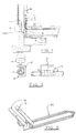
- FIGURE 1 shows in cross-section side elevation view a typical wood-frame wall 10 supported by a concrete foundation 11 over earth substrata 12.
- insulation 13 is first laid horizontally on the earth substrata 12.
- An underlying concrete slab 14 is then applied over the insulation 13.
- Several of the tube heat exchanger conduits 22 of the invention are then placed spacially over the lower concrete slab 14.
- An overlying layer of concrete 20 is then poured over the conduits 22.
- each conduit 22 is connected to the pair of manifolds 18 and 19 (shown in wall 10) according to the method shown in FIGURE 3.
- manifolds 18 and 19 are typically located in a space 15 between the wall 10 and interior wall finish 16.
- the final poured concrete floor slab 20 is applied as a matrix over the conduits 22 so that they are embedded in the concrete.
- FIGURE 2 a form of clamp 31 is shown by which one of the tubes 22 may be pinched to prevent fluid flow through the tube 22.
- the clamp 31 has aligned holes 32 and 33 through which the end portion of the tube 22 is inserted. Opposed squeezing portions 34 and 35 compress the tube 22 to close it. Adjustable temperature control may be achieved by tightening the screw 36 of the clamp 31 reducing the flow of fluid through the tube 22. This method can be used to custom regulate flow through the network of tubes and correct over-heating problems in certain areas. In addition, if a leak occurs individual tubes 22 can be clamped off to isolate damage while the operation of the remainder of the tube network system continues to be unaffected.
- FIGURE 3 shows in isometric view a typical connection of one triple-tube conduit 22 to one pair of manifold 18 and 19.
- the arrows indicate the direction of fluid flow through the manifolds. It is readily apparent in Figure 3 that each tube in the conduit constitutes a loop between the two manifolds 18 and 19 and that the heat-transfer fluid in the system flows through the full length of tube 22 when passing from one manifold to the other.
- FIGURE 3 also demonstrates that the alternate connection of the tubes 22 to the manifolds 18 and 19 dictate that fluid flow in adjacent tubes will be in opposite (counter flow) directions.
- This reverse directional flow in alternate tubes 22 creates temperature averaging in the triple-tube conduits and provides for uniform floor temperatures.
- the manifolds 18 and 19 typically have a minimum inside diameter of 2.5 cm and may be made of a plastic such as PVC or a metal such as copper.
- FIGURE 3 shows only one set of conduit tubes 22, it will be understood that a series of conduits are spacially disposed and connected along the lengths of the two manifolds. This enables a network of conduits to be spacially laid over a floor surface. Better heat distribution for counter current flows can be alternated in adjacent triple tube conduit combinations.
- FIGURE 4 depicts a transverse section through one conduit and shows the triple-tube arrangement of the tube heat exchanger.
- FIGURES 5, 6 and 7 illustrate the connection details of the triple-tube conduit of the tube heat exchanger to the manifold.
- FIGURE 5 shows the separation of the three tubes of a conduit a few centimetres from the end before connection to the manifold.
- Each tube 22 is cut to the appropriate length for alternate connection to the respective manifolds.
- FIGURES 5 and 6 illustrates the manner in which the three tube conduit is separated into independent tubes 22 by splitting one tube from another. This can be done by hand. This practice is performed at corners and at the ends where the conduit must pass through 90# or 180# bends.
- the tubes 22 can make smooth sharp turns when not attached to each other. No webs between the tubes are required.
- FIGURE 7 shows an enlarged side cut-away view of the connector 21 on the wall of the manifold 18.
- the connector 21 in combination with other parts enables the tube 22 to be connected to the manifold 18 without fear of the tube 22 working free over time from the manifold 18.
- the thermoplastic tube 22 has a specified inside and outside diameter.
- a compression nut 23 of the size of the outside diameter of the tube 22 slides over the tube 22.
- a ferrule 24 with inside diameter equal to the outside diameter of the tube 22 slides over the tube.
- a hollow cylindrical insert 25 having an outside diameter at least as great as the inside diameter of the tube 22 and having an axial length greater than the axial length of the cylindrical hole in the connecting fitting 26 penetrating into the manifold 18 fits inside the end of the tube 22.
- the tube 22 is inserted into the connecting fitting 26 on the manifold and the compression nut 23 is tightened on the ferrule 24 and the tube 22.
- the tube 22 is securely connected to the manifold 18 and cannot work free from constant contraction and expansion due to heat fluctuation.
- the end of the fitting 26 opposite the tube 22 is affixed to the manifold 18 by a ring of high temperature solder 30 around the fitting 26.
- the manifold-tube connecting fitting 26 protrudes 1.25 cm into the manifold 18. This protruding design discourages the possibility of foreign materials passing along the manifold 18 entering the thermoplastic tubing 22 and plugging the tubing over time. It also assists in balancing the water flow rate equally through all the tubes by creating a turbulence in the fluid.
- the triple-tube conduit 22 is unrolled from an extended length and cut to individually designed lengths for connection to a manifold pair.
- the length of tubing and the tubing arrangement are usually designed according to the heat loss properties of the specific building.
- a layer of mastic or a wire mesh of size 15 cm x 15 cm x 0.32 cm placed over the tube supporting surface ensures that the tubing will remain in its designed arrangement during the concrete pouring process.
- a radiant floor heating system is referred to in this disclosure because it is an obvious application for the subject tube heat exchanger invention. However, it is not intended to limit the invention to this example.
- the tube heat exchanger of the invention has a continuous multi-tube profile which is easily covered by thin slabs of concrete.
- the damaged tube can be clamped off (using the clamp in FIGURE 2) adjacent to the manifolds (above the concrete floor) and isolated so that the remainder of the system continues to function properly.
- selected tubes may be clamped off to isolate areas from the heat exchange fluid and thus make it possible to correct areas of over-heating.
Landscapes
- Engineering & Computer Science (AREA)
- Physics & Mathematics (AREA)
- Thermal Sciences (AREA)
- Chemical & Material Sciences (AREA)
- Combustion & Propulsion (AREA)
- Mechanical Engineering (AREA)
- General Engineering & Computer Science (AREA)
- Steam Or Hot-Water Central Heating Systems (AREA)
- Separation By Low-Temperature Treatments (AREA)
- Heat-Exchange Devices With Radiators And Conduit Assemblies (AREA)
- Power Steering Mechanism (AREA)
- Compression-Type Refrigeration Machines With Reversible Cycles (AREA)
Claims (8)
- Echangeur thermique pour transmettre une matière fluide contenant de la chaleur à contre-courant dans les conduits d'un échangeur thermique dans un plancher, comprenant:(a) un conduit conducteur de fluide creux ayant trois tubes conducteurs de fluide élastiques allongés cylindriques creux qui sont disposés parallèlement l'un par rapport à l'autre les tubes adjacents étant joints l'un à l'autre sur une partie substantielle de leur longueur, sans tissu entre eux; les tubes ayant des premières et secondes extrémités adaptées pour l'utilisation dans un échangeur thermique dans un plancher;(b) un premier manifold allongé conducteur de fluide creux comportant des raccords et orifices adaptés pour la connexion avec les premières extrémités des tubes, le manifold étant positionné à l'extérieur du plancher chauffé; et(c) un second manifold allongé conducteur de fluide creux comportant des orifices et raccords adaptés pour la connexion avec les secondes extrémités des tubes, les premières extrémités des deux tubes extérieurs étant connectées aux orifices et raccords du premier manifold et les extrémités opposées des mêmes deux tubes étant connectées aux orifices et raccords du second manifold, et la première extrémité du troisième tube du milieu contiguë aux premières extrémités des deux tubes extérieurs étant connectée à un orifice et raccord du second manifold tandis que l'extrémité opposée du troisième tube du milieu est connectée à un orifice et raccord du premier manifold le raccord étant connecté à l'orifice d'un manifold respectif.
- Echangeur thermique selon la revendication 1, dans lequel chaque raccord connecté à l'orifice d'un manifold respectif comprend:(a) un écrou creux qui comporte un filet de vis intérieur, et une bride saillante vers l'intérieur à l'une de ses extrémités, ledit écrou circonscrivant le tube:(b) une virole étant taillée en cône sur l'extérieur et ayant une configuration cylindrique creuse à l'intérieur circonscrivant le tube, la virole étant positionnée complètement à l'intérieur de l'écrou, la plus large extrémité de la virole conique extérieure étant contiguë à la bride de l'écrou;(c) un élément cylindrique creux qui est adapté pour être placé à l'intérieur d'une extrémité du tube; et(d) un élément tubulaire allongé ayant un filet de vis extérieur à l'une de ses extrémités adapté pour recevoir le filet de vis intérieur de l'écrou, l'extrémité éloignée du filet étant adaptée pour pénétrer dans l'orifice à l'intérieur du manifold, la combinaison de l'écrou et de l'élément tubulaire maintenant l'extrémité du tube entre la virole conique et l'élément cylindrique.
- Echangeur thermique selon la revendication 1 ou 2, dans lequel les premier et second manifolds sont disposés parallèlement l'un par rapport à l'autre.
- Echangeur thermique selon l'une quelconque des revendications précédentes, dans lequel une pluralité de raccords sont disposés spatialement dans des orifices le long de la longueur des premier et second manifolds.
- Echangeur thermique selon la revendication 4, dans lequel l'extrémité de l'élément tubulaire éloignée du filet de vis extérieur pénètre dans le manifold sur environ 50% provoquant de ce fait une turbulence dans la fluide s'écoulant dans le manifold.
- Echangeur thermique selon l'une quelconque des revendications 1 à 5, dans lequel les connexions des trois tubes de conduits adjacents sons alternées le long des longueurs des premier et second manifolds.
- Echangeur thermique selon l'une quelconque des revendications 2 à 6, dans lequel la surface extérieure de la virole est conique de sorte que l'extrémité fine se place sous l'extrémité de l'élément tubulaire au filet de vis extérieur.
- Echangeur thermique selon l'une quelconque des revendications 2 à 7, dans lequel le conduit est formé d'une matière thermosplastique.
Applications Claiming Priority (2)
| Application Number | Priority Date | Filing Date | Title |
|---|---|---|---|
| US38904189A | 1989-08-03 | 1989-08-03 | |
| US389041 | 1989-08-03 |
Publications (3)
| Publication Number | Publication Date |
|---|---|
| EP0416733A2 EP0416733A2 (fr) | 1991-03-13 |
| EP0416733A3 EP0416733A3 (en) | 1991-07-03 |
| EP0416733B1 true EP0416733B1 (fr) | 1995-01-11 |
Family
ID=23536581
Family Applications (1)
| Application Number | Title | Priority Date | Filing Date |
|---|---|---|---|
| EP90308036A Expired - Lifetime EP0416733B1 (fr) | 1989-08-03 | 1990-07-23 | Echangeur de chaleur |
Country Status (4)
| Country | Link |
|---|---|
| EP (1) | EP0416733B1 (fr) |
| AT (1) | ATE117066T1 (fr) |
| CA (1) | CA2000020C (fr) |
| DE (1) | DE69015930T2 (fr) |
Family Cites Families (3)
| Publication number | Priority date | Publication date | Assignee | Title |
|---|---|---|---|---|
| CH552179A (de) * | 1973-06-04 | 1974-07-31 | Schaerer Rene | Heizanlage zum gleichmaessigen beheizen einer bodenflaeche. |
| US4354546A (en) * | 1980-07-17 | 1982-10-19 | Bio-Energy Systems, Inc. | Header pair and double tube mat connection |
| US4762116A (en) * | 1984-07-11 | 1988-08-09 | S. W. Hart & Co. Pty. Ltd. | Solar water heaters especially intended for use with swimming pools |
-
1989
- 1989-10-03 CA CA002000020A patent/CA2000020C/fr not_active Expired - Fee Related
-
1990
- 1990-07-23 AT AT90308036T patent/ATE117066T1/de not_active IP Right Cessation
- 1990-07-23 DE DE69015930T patent/DE69015930T2/de not_active Expired - Fee Related
- 1990-07-23 EP EP90308036A patent/EP0416733B1/fr not_active Expired - Lifetime
Also Published As
| Publication number | Publication date |
|---|---|
| EP0416733A3 (en) | 1991-07-03 |
| CA2000020A1 (fr) | 1991-02-03 |
| EP0416733A2 (fr) | 1991-03-13 |
| DE69015930D1 (de) | 1995-02-23 |
| ATE117066T1 (de) | 1995-01-15 |
| DE69015930T2 (de) | 1995-09-07 |
| CA2000020C (fr) | 1993-11-02 |
Similar Documents
| Publication | Publication Date | Title |
|---|---|---|
| US4270596A (en) | Tube mat heat exchanger | |
| US5097893A (en) | Counter flow tube-manifold radiant floor heating system | |
| EP0993584B1 (fr) | Collecteur de distribution pour eau potable et chauffage local a l'eau chaude | |
| US10458727B2 (en) | Heat transfer using flexible fluid conduit | |
| US4011989A (en) | Metal building with integrated hot water heating system | |
| US7637286B2 (en) | Absorber for a pipe construction or sewer construction and pipe or sewer configuration provided with the absorber | |
| EP0351155A2 (fr) | Manifold extensible pour un système de distribution d'eau | |
| US5284204A (en) | Hydronic thermal distribution system for space heating and cooling | |
| US4941528A (en) | Ceiling made of metal panels | |
| US2338090A (en) | Connection for heat exchange systems | |
| US4354546A (en) | Header pair and double tube mat connection | |
| EP0416733B1 (fr) | Echangeur de chaleur | |
| EP1629235A1 (fr) | Systeme de chauffage avec distribution de fluide de transmission de chaleur dans des planchers finis | |
| US4349070A (en) | Tube mat heat exchanger | |
| EP0433869A1 (fr) | Paroi préfabriquée avec éléments de régulation thermique | |
| CN115388450B (zh) | 采暖系统管线弯头布设模块、分切方法及自适应铺设方法 | |
| JPH01277138A (ja) | 温水循環式床暖房装置 | |
| CZ287587B6 (en) | Heating element for surface heating and cooling | |
| EP0454754B1 (fr) | Dispositif pour la climatisation de locaux | |
| CN209782782U (zh) | 集分水器结构 | |
| JPH0744885Y2 (ja) | 熱交換装置 | |
| KR970005430Y1 (ko) | 온수온돌 배관 패널 | |
| CN212901727U (zh) | 一种地暖管铺设模块 | |
| CN219775862U (zh) | 分集水器 | |
| KR200190513Y1 (ko) | 시설하우스의 난방 배관장치 |
Legal Events
| Date | Code | Title | Description |
|---|---|---|---|
| PUAI | Public reference made under article 153(3) epc to a published international application that has entered the european phase |
Free format text: ORIGINAL CODE: 0009012 |
|
| AK | Designated contracting states |
Kind code of ref document: A2 Designated state(s): AT BE CH DE DK ES FR GB GR IT LI LU NL SE |
|
| PUAL | Search report despatched |
Free format text: ORIGINAL CODE: 0009013 |
|
| AK | Designated contracting states |
Kind code of ref document: A3 Designated state(s): AT BE CH DE DK ES FR GB GR IT LI LU NL SE |
|
| 17P | Request for examination filed |
Effective date: 19911216 |
|
| 17Q | First examination report despatched |
Effective date: 19920513 |
|
| GRAA | (expected) grant |
Free format text: ORIGINAL CODE: 0009210 |
|
| AK | Designated contracting states |
Kind code of ref document: B1 Designated state(s): AT BE CH DE DK ES FR GB GR IT LI LU NL SE |
|
| PG25 | Lapsed in a contracting state [announced via postgrant information from national office to epo] |
Ref country code: IT Free format text: LAPSE BECAUSE OF FAILURE TO SUBMIT A TRANSLATION OF THE DESCRIPTION OR TO PAY THE FEE WITHIN THE PRE;WARNING: LAPSES OF ITALIAN PATENTS WITH EFFECTIVE DATE BEFORE 2007 MAY HAVE OCCURRED AT ANY TIME BEFORE 2007. THE CORRECT EFFECTIVE DATE MAY BE DIFFERENT FROM THE ONE RECORDED.SCRIBED TIME-LIMIT Effective date: 19950111 Ref country code: LI Effective date: 19950111 Ref country code: CH Effective date: 19950111 Ref country code: NL Effective date: 19950111 Ref country code: AT Effective date: 19950111 Ref country code: BE Effective date: 19950111 Ref country code: ES Free format text: THE PATENT HAS BEEN ANNULLED BY A DECISION OF A NATIONAL AUTHORITY Effective date: 19950111 Ref country code: GR Free format text: LAPSE BECAUSE OF FAILURE TO SUBMIT A TRANSLATION OF THE DESCRIPTION OR TO PAY THE FEE WITHIN THE PRESCRIBED TIME-LIMIT Effective date: 19950111 Ref country code: DK Effective date: 19950111 |
|
| REF | Corresponds to: |
Ref document number: 117066 Country of ref document: AT Date of ref document: 19950115 Kind code of ref document: T |
|
| REF | Corresponds to: |
Ref document number: 69015930 Country of ref document: DE Date of ref document: 19950223 |
|
| PG25 | Lapsed in a contracting state [announced via postgrant information from national office to epo] |
Ref country code: SE Effective date: 19950411 |
|
| ET | Fr: translation filed | ||
| REG | Reference to a national code |
Ref country code: CH Ref legal event code: PL |
|
| NLV1 | Nl: lapsed or annulled due to failure to fulfill the requirements of art. 29p and 29m of the patents act | ||
| PG25 | Lapsed in a contracting state [announced via postgrant information from national office to epo] |
Ref country code: LU Free format text: LAPSE BECAUSE OF NON-PAYMENT OF DUE FEES Effective date: 19950731 |
|
| PLBE | No opposition filed within time limit |
Free format text: ORIGINAL CODE: 0009261 |
|
| STAA | Information on the status of an ep patent application or granted ep patent |
Free format text: STATUS: NO OPPOSITION FILED WITHIN TIME LIMIT |
|
| 26N | No opposition filed | ||
| PGFP | Annual fee paid to national office [announced via postgrant information from national office to epo] |
Ref country code: GB Payment date: 20010822 Year of fee payment: 12 |
|
| PGFP | Annual fee paid to national office [announced via postgrant information from national office to epo] |
Ref country code: FR Payment date: 20010825 Year of fee payment: 12 |
|
| PGFP | Annual fee paid to national office [announced via postgrant information from national office to epo] |
Ref country code: DE Payment date: 20010828 Year of fee payment: 12 |
|
| REG | Reference to a national code |
Ref country code: GB Ref legal event code: IF02 |
|
| PG25 | Lapsed in a contracting state [announced via postgrant information from national office to epo] |
Ref country code: GB Free format text: LAPSE BECAUSE OF NON-PAYMENT OF DUE FEES Effective date: 20020723 |
|
| PG25 | Lapsed in a contracting state [announced via postgrant information from national office to epo] |
Ref country code: DE Free format text: LAPSE BECAUSE OF NON-PAYMENT OF DUE FEES Effective date: 20030201 |
|
| GBPC | Gb: european patent ceased through non-payment of renewal fee |
Effective date: 20020723 |
|
| PG25 | Lapsed in a contracting state [announced via postgrant information from national office to epo] |
Ref country code: FR Free format text: LAPSE BECAUSE OF NON-PAYMENT OF DUE FEES Effective date: 20030331 |
|
| REG | Reference to a national code |
Ref country code: FR Ref legal event code: ST |