EP0416904A2 - Dispositif de réglage d'exposition pour caméra - Google Patents
Dispositif de réglage d'exposition pour caméra Download PDFInfo
- Publication number
- EP0416904A2 EP0416904A2 EP90309732A EP90309732A EP0416904A2 EP 0416904 A2 EP0416904 A2 EP 0416904A2 EP 90309732 A EP90309732 A EP 90309732A EP 90309732 A EP90309732 A EP 90309732A EP 0416904 A2 EP0416904 A2 EP 0416904A2
- Authority
- EP
- European Patent Office
- Prior art keywords
- light
- areas
- metering
- exposure
- luminance value
- Prior art date
- Legal status (The legal status is an assumption and is not a legal conclusion. Google has not performed a legal analysis and makes no representation as to the accuracy of the status listed.)
- Granted
Links
Images




Classifications
-
- G—PHYSICS
- G02—OPTICS
- G02B—OPTICAL ELEMENTS, SYSTEMS OR APPARATUS
- G02B7/00—Mountings, adjusting means, or light-tight connections, for optical elements
- G02B7/28—Systems for automatic generation of focusing signals
- G02B7/34—Systems for automatic generation of focusing signals using different areas in a pupil plane
Definitions
- This invention relates to an exposure control device in a camera.
- the present invention has been made in view of such a problem peculiar to the prior art and has as its object the provision of an exposure control device in a camera which can always obtain well-balanced exposure.
- an exposure control device which detects a defocus amount for each of a plurality of detection areas in the object field, sets a weighting amount corresponding to each of said plurality of detection areas on the basis of said plurality of detected defocus amounts, light-meters said plurality of detection areas and calculates proper exposure on the basis of the light metering information of said plurality of detection areas and said weighting amounts.
- the defocus amount is divided into one for the forward focusing area and one for the rearward focusing area, and even for the same defocus amount, the weighting amount of the forward focusing area and the weighting amount of the rearward focusing area are set to different values.
- a distance measuring element array for focus detection and light metering is effected by the use of the output of said distance measuring element array.
- light metering means for light-metering the outside of a plurality of detection areas, and when a defocus amount within a predetermined value exists among a plurality of calculated defocus amounts, proper exposure is calculated by the use of the light metering information in the plurality of detection areas, and when the defocus amount within the predetermined value does not exist, proper exposure is calculated by the use of the light metering information outside the plurality of detection areas.
- the focus detection areas are classified by the amount of out-of-focus and the result thereof is used for the calculation of proper exposure and therefore, there can be obtained photographs of well-balanced exposure and the problem peculiar to the prior art can be solved.
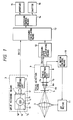
- Figure 1 is a block diagram showing an embodiment of the present invention.
- the reference numeral 4 designates a photo-taking lens which, in the present embodiment, is focus-controlled by an AF motor 11.
- Focus detection means 9 is provided rearwardly of the photo-taking lens 4, and re-coupling lenses 6a, 6b and photoelectric conversion element groups 7a, 7b are disposed rearwardly of the predetermined focal plane 5 of the lens 4.
- the outputs of the photoelectric conversion element groups 7a and 7b are input to a focus detection circuit 8, in which the imaged positions of the photoelectric conversion element groups 7a and 7b are compared with each other, whereby in-focus or out-of-focus is determined, and when the lens is out of focus, forward focusing or rearward focusing is determined and further, the defocus amount ⁇ AF (1) of the forward focusing or the rearward focusing is calculated.
- the output of the focus detection circuit 8 provided in the focus detection means 9 is input to focusing state classifying means 12 and AF motor control means 10.
- the AF motor control means 10 during out-of-focus, moves the lens 4 by an AF motor 11 and causes it to reach the in-focus state.
- the focusing state classifying means 12 classifies each detection area from the defocus amounts ⁇ AF (1) - ⁇ AF (6) into one of
- the reference numeral 3 denotes split metering means provided with a light metering photoelectric conversion element 1 and a light metering circuit 2.
- the light metering photoelectric conversion element 1 divides the object field into eight areas, i.e., central portions 1a-1c, the near-central portion 1d and marginal portions 1e-1h, as shown, and light-meters these areas.
- the positions of the central area 1a-1c in the light metering photoelectric conversion element 1 are in a relation corresponding to the distance measuring zone position in the focus detection means 9. The details of this correspondence relation will be described later with reference to Figure 2.
- the light metering outputs from the light metering photoelectric conversion element 1 divided into eight areas are input to the light metering circuit 2.
- the light metering circuit 2 converts each light metering output into a luminance value BV(I) by the use of a fully open F value signal F o , not shown, detected by the photo-taking lens 4, and outputs it to the exposure calculating means 13.
- the exposure calculating means 13 receives the output of the split metering means 3 and the output of the focusing state classifying means 12, calculates proper exposure B in accordance with algorithm which will be described later with reference to Figure 5 and outputs it to exposure control means 14. In response to this output, the exposure control means 14 controls an aperture 15 and a shutter 16.
- the lengthwise widths of the central areas 1a-1c of the light metering photoelectric conversion element 1 are set to substantially the same relative to the lengthwise width of the photoelectric conversion element group 7.
- areas A1 and A2 occupying the left one-third of the photoelectric conversion element group 7 are disposed correspondingly to the light metering area 1a at the left of the central portion
- areas A3 and A4 occupying the central one-third of the photoelectric conversion element group 7 are disposed correspondingly to the central light metering area 1b of the central portion
- areas A5 and A6 occupying the right one-third of the photoelectric conversion element group 7 are disposed correspondingly to the light metering area 1c at the right of the central portion.
- Figure 3A plots the areas A1-A6 of the photoelectric conversion element group as the horizontal axis and the defocus amount ⁇ AF and the direction thereof as the vertical axis, and the positional relation of the horizontal axis corresponds to Figures 3B and 3C.
- the areas A1-A6 each are an aggregate of photoelectric conversion elements, and each of these areas is designed so as to be capable of detecting the absolute value of the defocus amount and the direction thereof (forward focusing, in-focus or rearward focusing).
- the areas A1 and A2 represent the rearward focusing
- the areas A3-A5 are within a predetermined defocus amount and therefore represent in-focus
- the area A6 represents forward focusing.
- + represents forward focusing and - represents rearward focusing, and I corresponds to the areas A1-A6 of Figure 3A.
- Figure 5 shows the substance of the processing by the exposure calculating means 13.
- the program starts from S21, and at S22, the luminance output BV(I) of the split metering means 3 is read.
- the luminance difference between B R and B c is calculated, and when it exceeds 2EV, advance is made to S29, where the calculated value B c of only the central portion is given as the exposure value to B.
- advance is made to S30, where the average (Bc + B R )/2 of the central portion and the marginal portion is given as the exposure value to B.
- Figure 6 shows a second embodiment of the present invention.
- portions functionally similar to those in Figure 1 are given identical reference numerals and need not be described.
- photoelectric conversion means provided in the split metering means 3a is divided into five areas 21a-21e and that the light metering of the central portion is found from the output of the focus detection circuit 8.
- a light metering circuit 22 is designed to determine the luminance value in conformity with the charge accumulation time of each element of the CCD type photoelectric conversion element group 7 obtained in the focus detection circuit 8, but this is not always restrictive in carrying out the invention.
- Figure 7 shows the substance of the processing by exposure calculating means 23.
- the program starts, and at S42, the luminance values of the areas 21a-21e of the photoelectric conversion element 21 are read as BV(7)-BV(11). Subsequently, at S43, from the light metering circuit 22, the luminance values bv(i) of the respective elements of the distance measuring photoelectric conversion element group 7 are read up to bv(1) - bv(120). Then, at S44, from the focusing state classifying means 12, D(I) is read up to D(1) - D(6).
- the average value of bv(1) - bv(20) is allotted to BV(1)
- the average value of bv(21)-bv(40) is allotted to BV(2), and likewise up to BV(6).
- Figures 8 to 12 show a third embodiment of the present invention.
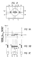
- This third embodiment is such that as shown in Figure 8, light metering areas 1a and 1e and distance measuring areas A1 and A2 corresponding thereto are newly disposed in the marginal portion of Figure 2.
- Figure 9A plots the distance measuring areas A1-A8 of the photoelectric conversion element group as the horizontal axis and plots the defocus amount ⁇ AF and the direction thereof as the vertical axis, and the positional relations between the distance measuring areas A1-A8 of the horizontal axis are shown in Figure 9B, and the positional relations between the light metering areas 1a-1e of the horizontal axis are shown in Figure 9C.
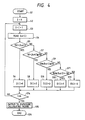
- the third embodiment is characterized in that in the process flow of Figure 11 by the focusing state classifying means, the boundary value of the classification of the defocus amount is changed by a photographing magnification M.
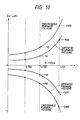
- Figure 10 shows examples of the curves of the boundary values ⁇ 1 - ⁇ 4 of the classification of the defocus amount obtained in the process of S100-S103 of Figure 11 relative to the photographing magnification T.
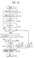
- Figure 12 shows the process flow by the exposure calculating means of the third embodiment executed subsequently to the process of Figure 11, and corresponds to the process flow of Figure 5.
- the flow of Figure 12 is the same as the flow of Figure 5.
- the focus detection area is divided into a plurality of units so that the in-focus state can be detected for each unit and by the use of this in-focus state information, weighting is effected on the outputs of the light metering area divided into a plurality of areas and proper exposure may be calculated and therefore, photographs of well-balanced exposure can be obtained.
- the light metering output is calculated by the use of the focus detection means, more effects can be expected such as the possibility of the light metering area being finely divided, and the elimination of the necessity of the alignment between the light metering means and the focus detection means.
Landscapes
- Physics & Mathematics (AREA)
- General Physics & Mathematics (AREA)
- Optics & Photonics (AREA)
- Exposure Control For Cameras (AREA)
- Focusing (AREA)
Priority Applications (1)
| Application Number | Priority Date | Filing Date | Title |
|---|---|---|---|
| EP96101422A EP0723172A3 (fr) | 1989-09-06 | 1990-09-05 | Dispositif de réglage d'exposition pour caméra |
Applications Claiming Priority (2)
| Application Number | Priority Date | Filing Date | Title |
|---|---|---|---|
| JP231041/89 | 1989-09-06 | ||
| JP23104189 | 1989-09-06 |
Related Child Applications (1)
| Application Number | Title | Priority Date | Filing Date |
|---|---|---|---|
| EP96101422.2 Division-Into | 1990-09-05 |
Publications (3)
| Publication Number | Publication Date |
|---|---|
| EP0416904A2 true EP0416904A2 (fr) | 1991-03-13 |
| EP0416904A3 EP0416904A3 (en) | 1991-06-26 |
| EP0416904B1 EP0416904B1 (fr) | 1996-11-20 |
Family
ID=16917353
Family Applications (2)
| Application Number | Title | Priority Date | Filing Date |
|---|---|---|---|
| EP19900309732 Expired - Lifetime EP0416904B1 (fr) | 1989-09-06 | 1990-09-05 | Dispositif de réglage d'exposition pour caméra |
| EP96101422A Withdrawn EP0723172A3 (fr) | 1989-09-06 | 1990-09-05 | Dispositif de réglage d'exposition pour caméra |
Family Applications After (1)
| Application Number | Title | Priority Date | Filing Date |
|---|---|---|---|
| EP96101422A Withdrawn EP0723172A3 (fr) | 1989-09-06 | 1990-09-05 | Dispositif de réglage d'exposition pour caméra |
Country Status (2)
| Country | Link |
|---|---|
| EP (2) | EP0416904B1 (fr) |
| DE (1) | DE69029181T2 (fr) |
Cited By (3)
| Publication number | Priority date | Publication date | Assignee | Title |
|---|---|---|---|---|
| EP0481729A3 (en) * | 1990-10-16 | 1992-07-15 | Nikon Corporation | Exposure calculation device for camera |
| EP0556598A1 (fr) * | 1992-01-27 | 1993-08-25 | Nikon Corporation | Dispositif de détection de focus |
| WO1994015249A1 (fr) * | 1992-12-28 | 1994-07-07 | Eastman Kodak Company | Groupement d'elements composites photometriques et telemetriques |
Family Cites Families (5)
| Publication number | Priority date | Publication date | Assignee | Title |
|---|---|---|---|---|
| JPS5689729A (en) * | 1979-12-21 | 1981-07-21 | Fuji Photo Film Co Ltd | Picture information input device |
| JPS61279829A (ja) * | 1985-06-06 | 1986-12-10 | Canon Inc | 測光装置を有するカメラ |
| JP2525351B2 (ja) * | 1985-08-08 | 1996-08-21 | キヤノン株式会社 | カメラ |
| US4851657A (en) * | 1985-12-23 | 1989-07-25 | Minolta Camera Kabushiki Kaisha | Focus condition detecting device using weighted center or contrast evaluation |
| US4977423A (en) * | 1988-02-08 | 1990-12-11 | Minolta Camera Kabushiki Kaisha | Exposure calculating apparatus |
-
1990
- 1990-09-05 EP EP19900309732 patent/EP0416904B1/fr not_active Expired - Lifetime
- 1990-09-05 EP EP96101422A patent/EP0723172A3/fr not_active Withdrawn
- 1990-09-05 DE DE69029181T patent/DE69029181T2/de not_active Expired - Fee Related
Cited By (6)
| Publication number | Priority date | Publication date | Assignee | Title |
|---|---|---|---|---|
| EP0481729A3 (en) * | 1990-10-16 | 1992-07-15 | Nikon Corporation | Exposure calculation device for camera |
| US5319416A (en) * | 1990-10-16 | 1994-06-07 | Nikon Corporation | Exposure calculation device for camera |
| EP0712026A3 (fr) * | 1990-10-16 | 1997-06-04 | Nippon Kogaku Kk | Dispositif de calcul d'exposition pour une caméra |
| EP0556598A1 (fr) * | 1992-01-27 | 1993-08-25 | Nikon Corporation | Dispositif de détection de focus |
| US5528330A (en) * | 1992-01-27 | 1996-06-18 | Nikon Corporation | Focus detecting apparatus |
| WO1994015249A1 (fr) * | 1992-12-28 | 1994-07-07 | Eastman Kodak Company | Groupement d'elements composites photometriques et telemetriques |
Also Published As
| Publication number | Publication date |
|---|---|
| DE69029181T2 (de) | 1997-05-22 |
| EP0416904A3 (en) | 1991-06-26 |
| EP0723172A2 (fr) | 1996-07-24 |
| EP0723172A3 (fr) | 1996-09-04 |
| DE69029181D1 (de) | 1997-01-02 |
| EP0416904B1 (fr) | 1996-11-20 |
Similar Documents
| Publication | Publication Date | Title |
|---|---|---|
| EP0480774B1 (fr) | Système de contrÔle pour caméra | |
| US4768052A (en) | Focus detecting device | |
| JP4018218B2 (ja) | 光学装置及び測距点選択方法 | |
| JPH10161013A (ja) | 環境認識装置及び環境認識装置を備えたカメラ | |
| EP0369806B1 (fr) | Dispositif pour corriger la mise au point | |
| US4910548A (en) | Camera with a multi-zone focus detecting device | |
| US5091742A (en) | Camera having an auto focusing device | |
| JP2605282B2 (ja) | 自動焦点調節装置 | |
| US5218395A (en) | Camera with a multi-zone focus detecting device | |
| US5623707A (en) | Auto focus adjustment system and auto focus adjustment method | |
| US5995144A (en) | Automatic focusing device using phase difference detection | |
| JPH1125263A (ja) | 対象物特徴点検出装置、焦点調節装置、露出制御装置及びカメラ | |
| JPH10142490A (ja) | 環境認識装置及びカメラ | |
| US5313246A (en) | Exposure control device in a camera | |
| US4905032A (en) | Automatic focus detecting device | |
| US5109154A (en) | Focus detection device having a plurality of means for forming light patterns provided at different distances from the optical axis | |
| US5410383A (en) | Focus detecting device | |
| US5258801A (en) | Focus detecting device | |
| EP2053438B1 (fr) | Détecteur de mise au point, dispositif de mésure de distance et dispositif optique d'ajustement de la focalisation | |
| US5315341A (en) | Method and apparatus for through-the-lens distance determination | |
| US5293034A (en) | Focus state detection device | |
| JP2001356384A (ja) | 測光装置 | |
| US5144357A (en) | Automatic focus detecting means | |
| EP0416904A2 (fr) | Dispositif de réglage d'exposition pour caméra | |
| EP0440170B1 (fr) | Caméra |
Legal Events
| Date | Code | Title | Description |
|---|---|---|---|
| PUAI | Public reference made under article 153(3) epc to a published international application that has entered the european phase |
Free format text: ORIGINAL CODE: 0009012 |
|
| AK | Designated contracting states |
Kind code of ref document: A2 Designated state(s): DE FR GB |
|
| PUAL | Search report despatched |
Free format text: ORIGINAL CODE: 0009013 |
|
| AK | Designated contracting states |
Kind code of ref document: A3 Designated state(s): DE FR GB |
|
| 17P | Request for examination filed |
Effective date: 19911204 |
|
| 17Q | First examination report despatched |
Effective date: 19930920 |
|
| GRAH | Despatch of communication of intention to grant a patent |
Free format text: ORIGINAL CODE: EPIDOS IGRA |
|
| GRAH | Despatch of communication of intention to grant a patent |
Free format text: ORIGINAL CODE: EPIDOS IGRA |
|
| GRAA | (expected) grant |
Free format text: ORIGINAL CODE: 0009210 |
|
| AK | Designated contracting states |
Kind code of ref document: B1 Designated state(s): DE FR GB |
|
| XX | Miscellaneous (additional remarks) |
Free format text: TEILANMELDUNG 96101422.2 EINGEREICHT AM 30/01/96. |
|
| ET | Fr: translation filed | ||
| REF | Corresponds to: |
Ref document number: 69029181 Country of ref document: DE Date of ref document: 19970102 |
|
| PLBE | No opposition filed within time limit |
Free format text: ORIGINAL CODE: 0009261 |
|
| STAA | Information on the status of an ep patent application or granted ep patent |
Free format text: STATUS: NO OPPOSITION FILED WITHIN TIME LIMIT |
|
| 26N | No opposition filed | ||
| PGFP | Annual fee paid to national office [announced via postgrant information from national office to epo] |
Ref country code: GB Payment date: 19990901 Year of fee payment: 10 |
|
| PGFP | Annual fee paid to national office [announced via postgrant information from national office to epo] |
Ref country code: DE Payment date: 19990906 Year of fee payment: 10 |
|
| PGFP | Annual fee paid to national office [announced via postgrant information from national office to epo] |
Ref country code: FR Payment date: 19990909 Year of fee payment: 10 |
|
| PG25 | Lapsed in a contracting state [announced via postgrant information from national office to epo] |
Ref country code: GB Free format text: LAPSE BECAUSE OF NON-PAYMENT OF DUE FEES Effective date: 20000905 |
|
| GBPC | Gb: european patent ceased through non-payment of renewal fee |
Effective date: 20000905 |
|
| PG25 | Lapsed in a contracting state [announced via postgrant information from national office to epo] |
Ref country code: FR Free format text: LAPSE BECAUSE OF NON-PAYMENT OF DUE FEES Effective date: 20010531 |
|
| PG25 | Lapsed in a contracting state [announced via postgrant information from national office to epo] |
Ref country code: DE Free format text: LAPSE BECAUSE OF NON-PAYMENT OF DUE FEES Effective date: 20010601 |
|
| REG | Reference to a national code |
Ref country code: FR Ref legal event code: ST |