EP0416992B1 - Lineare hydrophonische Antenne und dazugehörende elektronische Vorrichtung zum Aufheben der links-rechts Zweideutigkeit - Google Patents
Lineare hydrophonische Antenne und dazugehörende elektronische Vorrichtung zum Aufheben der links-rechts Zweideutigkeit Download PDFInfo
- Publication number
- EP0416992B1 EP0416992B1 EP90402430A EP90402430A EP0416992B1 EP 0416992 B1 EP0416992 B1 EP 0416992B1 EP 90402430 A EP90402430 A EP 90402430A EP 90402430 A EP90402430 A EP 90402430A EP 0416992 B1 EP0416992 B1 EP 0416992B1
- Authority
- EP
- European Patent Office
- Prior art keywords
- antenna
- flutes
- hydrophone
- antenna according
- signals
- Prior art date
- Legal status (The legal status is an assumption and is not a legal conclusion. Google has not performed a legal analysis and makes no representation as to the accuracy of the status listed.)
- Expired - Lifetime
Links
- 230000010363 phase shift Effects 0.000 claims description 21
- 230000001934 delay Effects 0.000 claims description 10
- 239000007788 liquid Substances 0.000 claims description 4
- 238000001514 detection method Methods 0.000 claims description 2
- 230000005484 gravity Effects 0.000 claims 2
- 239000007787 solid Substances 0.000 claims 1
- 239000013598 vector Substances 0.000 description 13
- 239000010690 paraffinic oil Substances 0.000 description 6
- 238000010586 diagram Methods 0.000 description 3
- 238000005259 measurement Methods 0.000 description 3
- 238000011084 recovery Methods 0.000 description 3
- 230000035945 sensitivity Effects 0.000 description 3
- XLYOFNOQVPJJNP-UHFFFAOYSA-N water Substances O XLYOFNOQVPJJNP-UHFFFAOYSA-N 0.000 description 3
- 238000004026 adhesive bonding Methods 0.000 description 2
- 238000005452 bending Methods 0.000 description 2
- 229920002635 polyurethane Polymers 0.000 description 2
- 239000004814 polyurethane Substances 0.000 description 2
- 238000011282 treatment Methods 0.000 description 2
- OKTJSMMVPCPJKN-UHFFFAOYSA-N Carbon Chemical compound [C] OKTJSMMVPCPJKN-UHFFFAOYSA-N 0.000 description 1
- 230000004913 activation Effects 0.000 description 1
- 230000005540 biological transmission Effects 0.000 description 1
- 230000015572 biosynthetic process Effects 0.000 description 1
- 229910052799 carbon Inorganic materials 0.000 description 1
- 230000002089 crippling effect Effects 0.000 description 1
- 230000003111 delayed effect Effects 0.000 description 1
- 239000011152 fibreglass Substances 0.000 description 1
- 239000012530 fluid Substances 0.000 description 1
- 239000012212 insulator Substances 0.000 description 1
- 239000002184 metal Substances 0.000 description 1
- 238000000034 method Methods 0.000 description 1
- 230000007935 neutral effect Effects 0.000 description 1
- 239000003921 oil Substances 0.000 description 1
- 239000013535 sea water Substances 0.000 description 1
- 230000006641 stabilisation Effects 0.000 description 1
- 238000011105 stabilization Methods 0.000 description 1
Images

Classifications
-
- G—PHYSICS
- G01—MEASURING; TESTING
- G01V—GEOPHYSICS; GRAVITATIONAL MEASUREMENTS; DETECTING MASSES OR OBJECTS; TAGS
- G01V1/00—Seismology; Seismic or acoustic prospecting or detecting
- G01V1/16—Receiving elements for seismic signals; Arrangements or adaptations of receiving elements
- G01V1/20—Arrangements of receiving elements, e.g. geophone pattern
- G01V1/201—Constructional details of seismic cables, e.g. streamers
Definitions
- the present invention relates to a linear hydrophonic antenna, consisting of omnidirectional and acoustically transparent hydrophonic sensors. It also relates to an electronic right-left ambiguity removal device associated with this antenna.
- a linear hydrophonic antenna generally consists of a "chain” of omnidirectional hydrophonic sensors contained in a sheath filled with an insulating oil. This sheath also contains the electronic modules associated with these sensors, this linear assembly forming a "flute", generally towed by a boat.
- a linear antenna of this type constitutes a passive sonar system whose directivity characteristics do not make it possible to know whether the detected object (such as a marine or underwater vessel) is on the right or on the left, above or in below.
- the detection distances being high (several kilometers in general), this amounts to having a right-left (or starboard-port) ambiguity which, for obvious reasons, must imperatively be removed.
- the observation sector is of the order of 120 degrees.
- the formation of these channels is carried out in a very conventional manner, by reshaping the signals from the hydrophonic sensors for a given direction.
- the hydrophonic sensors being omnidirectional, it is not possible to know a priori whether the signal received on a channel corresponds to a port or starboard direction.
- Each hydrophonic module is then formed by four sensors forming two orthogonal dipoles.
- a linear hydrophonic antenna of this type is described in the French patent application n ° 88 16 803, filed by the applicant on December 20, 1988. It is a linear modular antenna for which each hydrophonic module comprises two pairs of sensors hydrophonic forming two orthogonal dipoles, this module being associated with means for identifying the direction of the sources of picked up waves.
- Each of these modules is then constituted by a parallelepipedic support carrying a hydrophonic sensor (surface pressure sensor in this example) on each of its four lateral faces.
- the drawback of such a device is its complexity, and therefore its cost price.
- These three flutes are structurally identical, parallel to each other with their three corresponding ends located in the same plane orthogonal to their common axial direction, and they are linked together by a central core, which is rigid at least in the plane orthogonal to this axial direction, so as to form, together and in section in this same orthogonal plane, an advantageously isosceles triangle (and preferably equilateral).
- the densities of the insulating liquids contained in these three flutes and in which the hydrophonic sensors are embedded as well as generally at least part of their associated electronic blocks, are chosen such that they are identical for two of the flutes, while the density of the liquid insulator that contains the third flute is significantly different from that relating to these first two flutes, so that these first two flutes navigate at the same level, providing the whole good roll resistance.
- the three flutes are arranged in an equilateral triangle, and the distance between two flutes is substantially equal to one third of the wavelength which corresponds to the central frequency received.
- this same electronic device comprises means for correcting these delays or phase shifts as a function of the roll and / or torsion angles of the antenna which are measured by sensors placed on the hydrophonic antenna.
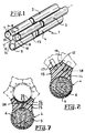
- this linear hydrophonic antenna 1 consists of three conventional "flutes" 2, 3, 4, which each traditionally comprise a "string” of hydrophonic (or hydrophone) sensors omnidirectional and acoustically transparent.
- Each flute has a sealed sheath 5 which is filled with an insulating paraffinic oil 6.
- the hydrophonic sensors not shown are conventionally held in this sheath by centralizers, and this sheath also contains the various associated electronic blocks, including the preamplifiers which are placed between the sensors, and the signal acquisition and processing electronics which is placed either in the center of the flute, or in a special section located at the head or tail of it.
- the densities of the paraffinic oils 6 that each of the three flutes 2, 3, 4 contain are not arbitrary either, but they are chosen so that the antenna 1 has good roll resistance, with an almost neutral buoyancy.
- the antenna 1 is intended to navigate with the flute 4 oriented downwards (that is to say towards the bottom of the sea) and, for this purpose, the latter is filled with a strong paraffinic oil. density (close to 1.5 for example), while the two upper flutes 2 and 3, intended to navigate in the same horizontal plane, are filled with a low density paraffinic oil (close to 0.8 for example).
- the assembly is subjected to two vertical forces opposite, which allows stabilization of navigation, especially in roll.
- the central core 10 is constituted by the assembly of three profiles 12, 13, 14 one of which, 14, is shown in detail and in cross section in Figure 2. They are shaped to present, between each pair flutes (4 and 3 for example), a hollow part 15 of concave shape, which has the advantage of limiting as much as possible the overall dimensions of the assembly, and therefore its weight in the air, and of delaying the appearance of a turbulent flow of water along the walls.
- each profile 14 also constitutes, as a single block, the sheath 5 of the corresponding flute 4.
- the three sections are assembled, to form the central core 10, by simple water-resistant bonding. Furthermore, a tenon 17 and mortise 18 securing device is also advantageously provided for the lower profile 14 in order to obtain good torsional rigidity, the tenon 17 being metallic.
- the antenna 1 is provided to present, in bending, sufficient flexibility to allow it to be wound on its reel (during storage).
- the three force recovery cables 16 are then fiberglass or carbon rods, guaranteeing the absence undulations during navigation and limiting longitudinal elongation.
- This "tri-flute" antenna 1 is designed to allow, by electronic processing, a port-starboard ambiguity lift, the mathematical principle of this ambiguity lift is now explained with the aid of FIGS. 3 to 5.
- the signals (vector) received respectively by the streamers 2, 3, and 4 are respectively designated by the references X, Z and Y, in these figures 3 to 5.
- phase shifts to be applied to the track signals of flutes 2 and 3 correspond to the paths projected on the bearing axis 90 degrees: for a angle G deposit, these phase shifts are worth ⁇ (120 ° - 60 °. In G).
- ⁇ 120 ° - 60 °. In G.
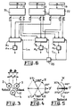
- FIG. 6 represents the block diagram of the electronic device associated with the antenna 1 allowing the lifting of right-left ambiguity compensated in roll.
- the three digitized signals V1X, V1Y, V1Z which correspond to the aforementioned first channel are all three applied to a block D1 comprising the phase shift or delay means to be applied to the three signals.
- the three signals V2X, V2Y, V2Z are all three applied to a second block D2 of phase shift or delay, and so on, the signals VNX, VNY, VNZ being applied to a Nth block DN of phase shift or delay, these phase shifts or delays being developed as explained above (with reference to FIGS. 3 to 5), and being corrected for the values of the roll and torsion angles measured by at least two sensors (block 25) located at the two ends of the antenna tri-flute.
- the corresponding angular values are introduced into the logic blocks D1 to DN by the links L1 to LN.
- the three flutes may not be placed in an equilateral triangle as long as it is isosceles.
- the densities of the paraffinic oils 6 could be chosen so that the navigation is done with a flute pointing upwards, and the two others navigating in the same horizontal plane, therefore under this first flute: in such a case, it would contain a paraffinic oil of higher density than that filling this first flute.
- FIG. 7 represents a variant of the profiles such as 14, which is then such that it gives way to a rigid central tube 26, made of metal or rigid PVC, which forms an anti-torsion bar.
- a rigid central tube 26 made of metal or rigid PVC, which forms an anti-torsion bar.
- the electronic blocks, or at least some of them, can be housed, holes 27 then being provided to allow the sealed passage of the connections, and of the recovery cables d efforts 28, 29 being also provided.
- the three sections such as 14 are fixed to the tube 26 either by gluing or by screwing (which then makes it possible to separate them if necessary).
- the tri-flute antenna is entirely rigid, in bending and in torsion, which is an advantage. On the other hand, it cannot be curved to allow it to be wound on a reel, which limits its length due to the space requirements for storage.
- the central core 10 can be produced separately, forming a part which is either massive or hollowed out in the center.
- the flutes 2, 3, 4 each produced separately with their sheath and possibly a small molded part, are then attached to the profile to which they are for example joined by gluing.
- this device achieves, for roll and / or torsion angles less than plus or minus 10 degrees, a port-starboard ambiguity lift with a loss of sensitivity of less than 1 dB .
- This unexpected result marks the superiority of the tri-flute because, thanks to the mechanical balancing obtained by the lower flute (filled with a heavy fluid), the rotations remain significantly less than plus or minus 10 degrees.
Landscapes
- Physics & Mathematics (AREA)
- Life Sciences & Earth Sciences (AREA)
- Engineering & Computer Science (AREA)
- Acoustics & Sound (AREA)
- Environmental & Geological Engineering (AREA)
- Geology (AREA)
- Remote Sensing (AREA)
- General Life Sciences & Earth Sciences (AREA)
- General Physics & Mathematics (AREA)
- Geophysics (AREA)
- Measurement Of Velocity Or Position Using Acoustic Or Ultrasonic Waves (AREA)
Claims (16)
- Lineare Unterwasserantenne (1), dadurch gekennzeichnet, daß sie aus drei "Flöten" (2, 3, 4) zusammengesetzt ist, die üblicherweise jeweils eine "Kette" von Unterwasserschallempfängern enthalten, wobei diese Unterwasserschallempfänger omnidirektionell und akustisch transparent sind, daß diese drei Flöten (2, 3, 4) strukturell identisch, ohne relative axiale Verschiebung parallel zueinander und miteinander durch ein zentrales Kernstück (10) verbunden sind, das zumindest in der zur Achse (11) der Antenne (1) senkrechten Ebene starr ist, so daß mit diesen drei und im querschnitt in dieser senkrechten Ebene ein gleichschenkliges Dreieck gebildet wird, wobei die Dichten von zwei dieser drei Flöten (2, 3, 4) identisch und von jener der dritten beträchtlich verschieden sind, so daß die letztere dafür vorgesehen ist, beim Navigieren entweder nach oben oder nach unten zu zeigen, und die zwei anderen, abgesehen von einer Rollbewegung, zum Navigieren im wesentlichen in derselben horizontalen Ebene vorgesehen sind.
- Unterwasserantenne gemäß dem Anspruch 1, dadurch gekennzeichnet, daß die drei Flöten (2, 3, 4) gemäß einem gleichseitigen Dreieck angeordnet sind.
- Unterwasserantenne gemäß dem Anspruch 1 oder dem Anspruch 2, dadurch gekennzeichnet, daß das Kernstück (10) so ausgebildet ist, daß es ein Kreuz (15) von konkaver Form zwischen jedem Paar von Flöten (2 und 3, 2 und 4, 3 und 4) bildet.
- Unterwasserantenne gemäß einem der Ansprüche 1 bis 3, dadurch gekennzeichnet daß das Kernstück (10) ein massives Teil bildet, in das ein oder mehrere Seile (16, 28, 29) zur Aufnahme von Belastungen eingelassen sind.
- Unterwasserantenne gemäß einem der Ansprüche 1 bis 4, dadurch gekennzeichnet, daß das Kernstück (10) durch eine Anordnung von drei im wesentlichen identischen Profilstählen (12, 13, 14) gebildet wird.
- Unterwasserantenne gemäß dem Anspruch 5, dadurch gekennzeichnet, daß jeder dieser Profilstähle (12, 13, 14) einstückig auch das Hüllrohr (5) der entsprechenden Flöte (2, 3, 4) enthält.
- Unterwasserantenne gemäß einem der Ansprüche 1 bis 6, dadurch gekennzeichnet, daß das Kernstück (10) an einem zentralen starren Rohr (26) angebracht ist.
- Unterwasserantenne gemäß einem der Ansprüche 1 bis 5, dadurch gekennzeichnet, daß das Kernstück (10) getrennt realisiert wird und daß die drei Flöten (2, 3, 4) mit ihren Hüllrohren (5) an dieses Kernstück angebracht sind.
- Unterwasserantenne gemäß einem der Ansprüche 1 bis 8, dadurch gekennzeichnet, daß eine der Flöten (4) eine isolierende Flüssigkeit (6) enthält, deren Dichte in der Größenordnung von 1,5 liegt, während die anderen zwei (2, 3) eine isolierende Flüssigkeit enthalten, deren Dichte in der Größenordnung von 0,8 liegt.
- Unterwasserantenne gemäß einem der Ansprüche 1 bis 9, dadurch gekennzeichnet, daß der Achsabstand (e) zwischen den beiden Flöten (2, 3), die für die Steuerung in derselben Ebene vorgesehen sind, in der Größenordnung von einem Drittel der Wellenlänge der Betriebsmittenfrequenz (f) dieser Antenne liegt.
- Elektronikschaltung zur Beseitigung der Rechts-Links-Unbestimmtheit , die sich zum Anschluß an eine Unterwasserantenne gemäß einem der Ansprüche 1 bis 10 eignet, wobei diese Schaltung üblicherweise Mittel (19, 20, 21) zum Erfassen der Signale (X, Y, Z) enthält, die von den Hydrophonen der drei Flöten (2, 4, 3) empfangen werden, dadurch gekennzeichnet, daß sie außerdem ausgestattet ist mit:- Mitteln (22, 23, 24) zum Bilden von Kanälen für eine bestimmte Anzahl (N) von ausgewählten Richtungen;- Mitteln (D1, D2, ..., DN), um jede Gruppe von drei Kanalsignalen (V1X, V1Y, V1Z, dann V2X, V2Y, V2Z..., dann VNX, VNY, VNZ) mit drei Verzögerungen oder drei Phasenverschiebungen zu versehen; und- Mitteln (A₁,A₂,...,AN) zur Addition der Gruppen mit den drei Signalen, die so verarbeitet N Kanalsignale (V₁ ... VN) liefern.
- Elektronikschaltung gemäß dem Anspruch 11, dadurch gekennzeichnet, daß diese Verzögerungen oder Phasenverschiebungen festgestellt werden, damit die Richtcharakteristik jedes Kanalsignals entweder an der Backbordseite oder der Steuerbordseite eine Nullstelle aufweist.
- Elektronikschaltung gemäß einem der Ansprüche 11 oder 12, dadurch gekennzeichnet, daß die verwendeten Phasenverschiebungen oder Verzögerungen für die mittlere Flöte (4) 0° und für die zwei anderen Flöten (2, 3) ±(120° - A*sin G) betragen, wobei A die Phase ist, die der Wegdifferenz (d) zwischen jeder der zwei Flöten (2, 3) und der mittleren Flöte (4) entspricht und G der Peilwinkel des betrachteten Kanals ist.
- Elektronikschaltung gemäß einem der Ansprüche 11 bis 13, dadurch gekennzeichnet, daß sie außerdem Mittel (25, L1 bis LN) zur von den Roll- und/oder Verdrehungswinkeln der Antenne (1) abhängigen Korrektur dieser Verzögerungen oder Phasenverschiebungen enthält.
- Schaltung gemäß einem der Ansprüche 11 bis 14, dadurch gekennzeichnet, daß die nach Verarbeitung aufgenommenen Ausgangssignale (V1, V2 ... VN) einer Schaltung zur Analyse und Verarbeitung derselben für die endgültige Ortung des Objekts zugeführt werden.
- Schaltung gemäß einem der Ansprüche 11 bis 15, dadurch gekennzeichnet, daß die Verzögerungen oder Phasenverschiebungen auf der Ebene der Hydrophonsignale realisiert werden.
Applications Claiming Priority (2)
| Application Number | Priority Date | Filing Date | Title |
|---|---|---|---|
| FR8911749A FR2651950B1 (fr) | 1989-09-08 | 1989-09-08 | Antenne hydrophonique lineaire et dispositif electronique de levee d'ambiguite droite-gauche associe a cette antenne. |
| FR8911749 | 1989-09-08 |
Publications (2)
| Publication Number | Publication Date |
|---|---|
| EP0416992A1 EP0416992A1 (de) | 1991-03-13 |
| EP0416992B1 true EP0416992B1 (de) | 1993-03-17 |
Family
ID=9385247
Family Applications (1)
| Application Number | Title | Priority Date | Filing Date |
|---|---|---|---|
| EP90402430A Expired - Lifetime EP0416992B1 (de) | 1989-09-08 | 1990-09-04 | Lineare hydrophonische Antenne und dazugehörende elektronische Vorrichtung zum Aufheben der links-rechts Zweideutigkeit |
Country Status (4)
| Country | Link |
|---|---|
| US (1) | US5058082A (de) |
| EP (1) | EP0416992B1 (de) |
| DE (1) | DE69001109T2 (de) |
| FR (1) | FR2651950B1 (de) |
Cited By (3)
| Publication number | Priority date | Publication date | Assignee | Title |
|---|---|---|---|---|
| RU2496119C1 (ru) * | 2012-04-26 | 2013-10-20 | Открытое акционерное общество "Концерн "Центральный научно-исследовательский институт "Электроприбор" | Антенный модуль |
| RU2497142C1 (ru) * | 2012-04-26 | 2013-10-27 | Открытое акционерное общество "Концерн "Центральный научно-исследовательский институт "Электроприбор" | Приемная гидроакустическая антенна и способ оценки амплитудно-частотных характеристик гидроакустических приемников |
| RU2713018C1 (ru) * | 2018-11-09 | 2020-02-03 | Акционерное общество "Концерн "Центральный научно-исследовательский институт "Электроприбор" | Антенный модуль |
Families Citing this family (22)
| Publication number | Priority date | Publication date | Assignee | Title |
|---|---|---|---|---|
| FR2685848B1 (fr) * | 1991-12-26 | 1994-02-25 | Thomson Csf | Antenne acoustique lineaire. |
| US5367971A (en) * | 1992-03-12 | 1994-11-29 | Australian Sonar Systems Pty Ltd. | Towed acoustic array |
| DE4341364C2 (de) * | 1993-12-04 | 2003-06-18 | Stn Atlas Elektronik Gmbh | Verfahren zur Seitenkennung für eine Peilanlage mit Schleppantenne |
| FR2727765B1 (fr) * | 1994-12-06 | 1997-01-10 | Thomson Csf | Procede de reception avec levee d'ambiguite pour une antenne acoustique lineaire remorquee |
| DE4445549C1 (de) * | 1994-12-20 | 1996-03-07 | Stn Atlas Elektronik Gmbh | Schleppantenne |
| FR2744870B1 (fr) * | 1996-02-13 | 1998-03-06 | Thomson Csf | Procede pour controler la navigation d'une antenne acoustique lineaire remorquee, et dispositifs pour la mise en oeuvre d'un tel procede |
| DE19720991C2 (de) * | 1997-05-20 | 2001-02-22 | Stn Atlas Elektronik Gmbh | Schleppantenne |
| FR2764160B1 (fr) * | 1997-05-27 | 1999-08-27 | Thomson Marconi Sonar Sas | Transducteur electrodynamique pour acoustique sous-marine |
| FR2795527B1 (fr) | 1999-06-22 | 2001-09-07 | Thomson Marconi Sonar Sas | Systeme de prospection sismique sous-marine, notamment pour grands fonds |
| RU2190237C2 (ru) * | 2000-11-24 | 2002-09-27 | Федеральное государственное унитарное предприятие "Центральный научно-исследовательский институт "Морфизприбор" | Приемный тракт гидроакустической станции с линейной антенной, устраняющий неоднозначность определения направления прихода сигнала |
| FR2822959B1 (fr) * | 2001-03-30 | 2003-07-25 | Thomson Marconi Sonar Sas | Systeme de detection sous-marine basse frequence remorque |
| FR2822960B3 (fr) * | 2001-03-30 | 2003-06-20 | Thomson Marconi Sonar Sas | Systeme de detection sous-marine basse frequence remorque |
| FR2828936B1 (fr) | 2001-08-24 | 2003-12-05 | Thomson Marconi Sonar Sas | Procede de traitement des signaux d'une antenne lineaire remorquee |
| US6697300B1 (en) | 2002-09-13 | 2004-02-24 | General Dynamics Advanced Information Systems, Inc. | Method and apparatus for determining the positioning of volumetric sensor array lines |
| FR2851339B1 (fr) * | 2003-02-14 | 2006-01-06 | Thales Sa | Sonar passif remorque a antenne multifaisceaux et procede de realisation d'une telle antenne. |
| GB0521292D0 (en) * | 2005-10-19 | 2005-11-30 | Go Science Ltd | Submersible vehicle |
| RU2336542C2 (ru) * | 2006-02-07 | 2008-10-20 | Сергей Прохорович Шолькин | Способ компоновки сейсмоприемника |
| FR2905766B1 (fr) * | 2006-09-08 | 2011-09-30 | Ixsea | Sonar a antenne deformable et procede associe de traitement du signal pour former une antenne synthetique |
| FR2909457B1 (fr) * | 2006-12-01 | 2009-01-23 | Thales Sa | Procede d'elimination de sources fantomes pour un sonar passif comportant plusieurs antennes lineaires. |
| CA2810932C (en) | 2010-09-13 | 2015-10-13 | Ultra Electronics Maritime Systems Inc. | Defocusing beamformer method and system for a towed sonar array |
| RU2466420C1 (ru) * | 2011-06-23 | 2012-11-10 | Открытое акционерное общество "Концерн "Центральный научно-исследовательский институт "Электроприбор" | Гидроакустическая антенна и способ обработки сигналов в ней |
| US10209379B2 (en) * | 2016-04-27 | 2019-02-19 | Proteus Technologies | Ship-towed hydrophone volumetric array system apparatus |
Family Cites Families (5)
| Publication number | Priority date | Publication date | Assignee | Title |
|---|---|---|---|---|
| US1482980A (en) * | 1919-06-27 | 1924-02-05 | Submarine Signal Co | Direction detector for submarine sounds |
| US3939469A (en) * | 1944-03-15 | 1976-02-17 | The United States Of America As Represented By The Secretary Of The Navy | Detection streamer |
| GB1138133A (en) * | 1966-05-03 | 1968-12-27 | Buzzards Corp | Conductor cable |
| FR1541829A (fr) * | 1967-10-04 | 1968-10-11 | Continental Oil Co | Perfectionnements apportés aux appareils de réglage de profondeur d'immersion pour câbles de prospection sismique et analogues |
| US4078223A (en) * | 1976-09-10 | 1978-03-07 | Western Geophysical Co. Of America | Geophone and seismic cable assembly |
-
1989
- 1989-09-08 FR FR8911749A patent/FR2651950B1/fr not_active Expired - Lifetime
-
1990
- 1990-08-23 US US07/571,217 patent/US5058082A/en not_active Expired - Lifetime
- 1990-09-04 EP EP90402430A patent/EP0416992B1/de not_active Expired - Lifetime
- 1990-09-04 DE DE9090402430T patent/DE69001109T2/de not_active Expired - Lifetime
Cited By (3)
| Publication number | Priority date | Publication date | Assignee | Title |
|---|---|---|---|---|
| RU2496119C1 (ru) * | 2012-04-26 | 2013-10-20 | Открытое акционерное общество "Концерн "Центральный научно-исследовательский институт "Электроприбор" | Антенный модуль |
| RU2497142C1 (ru) * | 2012-04-26 | 2013-10-27 | Открытое акционерное общество "Концерн "Центральный научно-исследовательский институт "Электроприбор" | Приемная гидроакустическая антенна и способ оценки амплитудно-частотных характеристик гидроакустических приемников |
| RU2713018C1 (ru) * | 2018-11-09 | 2020-02-03 | Акционерное общество "Концерн "Центральный научно-исследовательский институт "Электроприбор" | Антенный модуль |
Also Published As
| Publication number | Publication date |
|---|---|
| US5058082A (en) | 1991-10-15 |
| DE69001109T2 (de) | 1993-06-24 |
| EP0416992A1 (de) | 1991-03-13 |
| DE69001109D1 (de) | 1993-04-22 |
| FR2651950B1 (fr) | 1992-04-17 |
| FR2651950A1 (fr) | 1991-03-15 |
Similar Documents
| Publication | Publication Date | Title |
|---|---|---|
| EP0416992B1 (de) | Lineare hydrophonische Antenne und dazugehörende elektronische Vorrichtung zum Aufheben der links-rechts Zweideutigkeit | |
| FR2884930A1 (fr) | Systeme de flute marine et son procede associe | |
| EP0267840B1 (de) | Verfahren und Gerät zur Positionsbestimmung von Unterwasserobjekten mit Bezug auf das sie ziehende Schiff | |
| CA2786411A1 (fr) | Procede et dispositif d'acquisition de donnees sismiques marines | |
| FR2985039A1 (fr) | Noeud sous-marin couple avec l'eau pour des etudes sismiques | |
| FR2984526A1 (fr) | Controleur et procede pour diriger des sources | |
| FR3075974A1 (fr) | Drone marin de surface et procede de caracterisation d'un milieu subaquatique mis en œuvre par un tel drone | |
| EP0800656A1 (de) | Verfahren zum erzeugen von akustischen wellen für sonar | |
| EP3850394B1 (de) | Verfahren zur bestimmung einer tiefe oder eines bathymetrischen profils auf basis eines mittleren schallgeschwindigkeitsprofils, verfahren zur bestimmung solch eines geschwindigkeitsprofils und zugehöriges sonarsystem | |
| FR2769372A1 (fr) | Procede de correction des effets des mouvements parasites de l'antenne dans un sonar a antenne synthetique | |
| EP0796439B1 (de) | Empfangsverfahren mit mehrdeutigkeitsentfernung für akustische lineare schleppantenne | |
| WO2007132125A2 (fr) | Sonar frontal ameliore | |
| EP1557688B1 (de) | Akustisches Messsystem zur Ortung von Rauschquellen | |
| FR2590679A1 (fr) | Procede de determination passive de donnees de reperage d'un vehicule | |
| FR2652164A1 (fr) | Procede de formation de voies pour sonar, notamment pour sonar remorque. | |
| EP0375498A1 (de) | Modulare lineare Hydrophonrichtantenne | |
| WO2003019224A1 (fr) | Procede de traitement des signaux d'une antenne lineaire remorquee | |
| FR3003042A1 (fr) | Conception de flute marine pour la prospection geophysique | |
| EP0619025B1 (de) | Lineare akustische antenne | |
| FR2702569A1 (fr) | Sonar pour détecter les objets enfouis. | |
| FR2473732A1 (fr) | Procede de prospection sismique marine | |
| EP0628172B1 (de) | Verfahren zur Strahlstabilisierung und Strahlbündelung und Sonar zu dessen Anwendung | |
| EP0458947A1 (de) | Verfahren und vorrichtung zur datenerfassung von seismischen messwerten aus bohrlöchern in zwei entgegengesetzten richtungen. | |
| WO2004077089A1 (fr) | Sonar passif remorque a antenne multifaisceaux et procede de realisation d’une telle antenne | |
| FR2902893A1 (fr) | Recepteur sonar a lobes lateraux reduits. |
Legal Events
| Date | Code | Title | Description |
|---|---|---|---|
| PUAI | Public reference made under article 153(3) epc to a published international application that has entered the european phase |
Free format text: ORIGINAL CODE: 0009012 |
|
| AK | Designated contracting states |
Kind code of ref document: A1 Designated state(s): DE GB IT |
|
| 17P | Request for examination filed |
Effective date: 19910812 |
|
| 17Q | First examination report despatched |
Effective date: 19920827 |
|
| GRAA | (expected) grant |
Free format text: ORIGINAL CODE: 0009210 |
|
| AK | Designated contracting states |
Kind code of ref document: B1 Designated state(s): DE GB IT |
|
| ITF | It: translation for a ep patent filed | ||
| REF | Corresponds to: |
Ref document number: 69001109 Country of ref document: DE Date of ref document: 19930422 |
|
| GBT | Gb: translation of ep patent filed (gb section 77(6)(a)/1977) |
Effective date: 19930420 |
|
| PLBE | No opposition filed within time limit |
Free format text: ORIGINAL CODE: 0009261 |
|
| STAA | Information on the status of an ep patent application or granted ep patent |
Free format text: STATUS: NO OPPOSITION FILED WITHIN TIME LIMIT |
|
| RAP2 | Party data changed (patent owner data changed or rights of a patent transferred) |
Owner name: THOMSON-CSF |
|
| 26N | No opposition filed | ||
| REG | Reference to a national code |
Ref country code: GB Ref legal event code: IF02 |
|
| PGFP | Annual fee paid to national office [announced via postgrant information from national office to epo] |
Ref country code: GB Payment date: 20090902 Year of fee payment: 20 |
|
| PGFP | Annual fee paid to national office [announced via postgrant information from national office to epo] |
Ref country code: DE Payment date: 20090827 Year of fee payment: 20 |
|
| PGFP | Annual fee paid to national office [announced via postgrant information from national office to epo] |
Ref country code: IT Payment date: 20090912 Year of fee payment: 20 |
|
| REG | Reference to a national code |
Ref country code: GB Ref legal event code: PE20 Expiry date: 20100903 |
|
| PG25 | Lapsed in a contracting state [announced via postgrant information from national office to epo] |
Ref country code: GB Free format text: LAPSE BECAUSE OF EXPIRATION OF PROTECTION Effective date: 20100903 |
|
| PG25 | Lapsed in a contracting state [announced via postgrant information from national office to epo] |
Ref country code: DE Free format text: LAPSE BECAUSE OF EXPIRATION OF PROTECTION Effective date: 20100904 |