EP0417022A1 - Scellé infalsifiable destiné notamment aux conteneurs de tous types - Google Patents
Scellé infalsifiable destiné notamment aux conteneurs de tous types Download PDFInfo
- Publication number
- EP0417022A1 EP0417022A1 EP90440078A EP90440078A EP0417022A1 EP 0417022 A1 EP0417022 A1 EP 0417022A1 EP 90440078 A EP90440078 A EP 90440078A EP 90440078 A EP90440078 A EP 90440078A EP 0417022 A1 EP0417022 A1 EP 0417022A1
- Authority
- EP
- European Patent Office
- Prior art keywords
- cable
- seal
- tubular opening
- opening
- housing
- Prior art date
- Legal status (The legal status is an assumption and is not a legal conclusion. Google has not performed a legal analysis and makes no representation as to the accuracy of the status listed.)
- Granted
Links
- 229910000831 Steel Inorganic materials 0.000 claims abstract description 11
- 239000010959 steel Substances 0.000 claims abstract description 11
- 239000012780 transparent material Substances 0.000 claims abstract description 8
- 229910052751 metal Inorganic materials 0.000 claims description 16
- 239000002184 metal Substances 0.000 claims description 16
- 229920003023 plastic Polymers 0.000 claims description 11
- 239000000463 material Substances 0.000 claims description 2
- 230000006866 deterioration Effects 0.000 claims 1
- 238000006073 displacement reaction Methods 0.000 claims 1
- 229910052782 aluminium Inorganic materials 0.000 description 4
- XAGFODPZIPBFFR-UHFFFAOYSA-N aluminium Chemical compound [Al] XAGFODPZIPBFFR-UHFFFAOYSA-N 0.000 description 4
- 230000000694 effects Effects 0.000 description 3
- 230000000873 masking effect Effects 0.000 description 2
- 230000000007 visual effect Effects 0.000 description 2
- 238000000465 moulding Methods 0.000 description 1
- 229920005989 resin Polymers 0.000 description 1
- 239000011347 resin Substances 0.000 description 1
- 238000007789 sealing Methods 0.000 description 1
- 229920003002 synthetic resin Polymers 0.000 description 1
- 239000000057 synthetic resin Substances 0.000 description 1
Images


Classifications
-
- G—PHYSICS
- G09—EDUCATION; CRYPTOGRAPHY; DISPLAY; ADVERTISING; SEALS
- G09F—DISPLAYING; ADVERTISING; SIGNS; LABELS OR NAME-PLATES; SEALS
- G09F3/00—Labels, tag tickets, or similar identification or indication means; Seals; Postage or like stamps
- G09F3/02—Forms or constructions
- G09F3/03—Forms or constructions of security seals
- G09F3/0305—Forms or constructions of security seals characterised by the type of seal used
- G09F3/0311—Forms or constructions of security seals characterised by the type of seal used having arrow-like sealing means
-
- G—PHYSICS
- G09—EDUCATION; CRYPTOGRAPHY; DISPLAY; ADVERTISING; SEALS
- G09F—DISPLAYING; ADVERTISING; SIGNS; LABELS OR NAME-PLATES; SEALS
- G09F3/00—Labels, tag tickets, or similar identification or indication means; Seals; Postage or like stamps
- G09F3/02—Forms or constructions
- G09F3/03—Forms or constructions of security seals
- G09F3/0305—Forms or constructions of security seals characterised by the type of seal used
- G09F3/0347—Forms or constructions of security seals characterised by the type of seal used having padlock-type sealing means
- G09F3/0352—Forms or constructions of security seals characterised by the type of seal used having padlock-type sealing means using cable lock
-
- G—PHYSICS
- G09—EDUCATION; CRYPTOGRAPHY; DISPLAY; ADVERTISING; SEALS
- G09F—DISPLAYING; ADVERTISING; SIGNS; LABELS OR NAME-PLATES; SEALS
- G09F3/00—Labels, tag tickets, or similar identification or indication means; Seals; Postage or like stamps
- G09F3/02—Forms or constructions
- G09F3/03—Forms or constructions of security seals
- G09F3/0382—Seals with transparent casing
Definitions
- the present invention relates to a tamper-proof seal intended in particular for containers of all types, such as wagons, trailers, tanks, maritime containers or the like.
- the object of the present invention is to provide a solution to the problem thus posed by proposing a seal which in this respect offers all the desired security guarantees.
- the present invention thus relates to a tamper-proof seal which is essentially characterized in that it consists of a body of transparent material in which are inserted on the one hand a metal plate bearing the acronym and the identification number of the loading and on the other hand the end of a steel cable, the other end of which is intended to be introduced into a tubular opening made in said body and provided with means for fixing said end which prohibit its removal from said opening tubular except destroying said fixing means irreversibly.
- the transparent material used to produce the body of the seal according to the invention advantageously consists of a synthetic resin of the polymethacrytal type, the metal plate possibly being an aluminum plate.
- the steel cable used advantageously consists of a twisted steel wire which cannot be re-bonded in the event of a cut.
- the free end of the steel cable is extended by a metallic mass comprising, at a short distance from its end, a frustoconical narrowing terminated by a circular groove forming a stop, and the means for fixing said free end, arranged in the tubular opening formed in the body of the seal, consist of a set of several steel needles partially embedded in the body of the seal and the end of which opens obliquely into said opening tubular, a short distance from its bottom, towards which they are oriented so as to come to bear on the metal mass near the circular groove forming a stop.
- Such a device makes it possible to guarantee the impossibility of reusing said fixing means, the needles being irreversibly destroyed when the cable is forced out of its housing.
- the tubular opening can be extended laterally, a short distance from its outlet orifice, by a also tubular housing whose axis is perpendicular to it and which houses a weight separated from the bottom of said opening by a spring which l applies against a rod arranged transversely to the opening of its housing, said rod being held by any suitable means and being extended, to that of its ends close to the outlet of the tubular opening, by a leaf spring arranged obliquely and oriented towards the bottom of said tubular opening, so as to come to bear on the steel cable and to be driven towards the outlet orifice when the latter is withdrawn, since it then engages on the circular groove formed on the metal mass which extends the end of said cable, which has the effect of releasing the weight which, under the effect of the thrust exerted by the spring, moves tran sversally to the tubular opening, coming to be housed by its end in a recess made for this purpose opposite its housing.
- This device makes it possible to prevent the reintroduction of the cable into the tubular opening after breaking the seal, thereby preventing any possibility of masking its break-in.
- the free end of the cable is extended by a plastic tip provided with fins which give it the shape of a harpoon and which are housed in a widening in the form of cone formed at the base of the tubular opening, preventing the cable from being removed unless the said fins are broken.
- An additional device can increase the security of use of this type of seal, consisting of two metal cylinders arranged above the plastic end-piece and crossed by the cable, the lower cylinder being in contact with the plastic end-piece and being separated from the upper cylinder by a space at which, when the seal is closed, are two enlargements of the tubular opening containing two lugs intended to be broken by the lower cylinder in the event of breaking of the seal, the upper cylinder having the function of preventing access from the outside to said lugs with a view to spreading them using 'an instrument.
- the fixed end of the seal cable according to the invention can be simply embedded in the body of transparent material, but it can also be taken in a metallic mass inserted in the body of the seal, which makes its tearing even more difficult.
- the metal plate of the seal according to the invention can moreover be embedded in the body of transparent material, in which case a window made in the latter allows the affixing of an identification number using a clamp. customs. It can also be inserted laterally in the body of transparent material where it is held securely by any suitable means, part of this plate being free to allow customs marking.
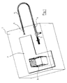
- the seal according to the invention consists of a body 1 of transparent resin in which is embedded an aluminum plate 2 intended to carry at its upper part the acronyms and identification number of the load and surmounted at its lower part by a window 3 formed in said body 1 so as to allow the affixing of a customs control number.
- a steel cable 4 is fixed by one of its ends 5 in the body 1, in which said end 5 is embedded, its other end 6 being able to be introduced into a tubular opening 7 which is described in detail below.
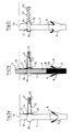
- the tubular opening 7 has at its lower part an enlargement 8 at the level of which the needles 9 partially embedded in the body open out.
- a short distance from the orifice 10 of inlet of the tubular opening 7 is formed, perpendicular to the opening 7, a cylindrical housing 11 housing a counterweight 12 and a spring 13 positioned at the bottom of said housing 11.
- a rod 14 is disposed in front of the opening of the housing 11, being housed by one of its ends in a recess 15 formed at the base of the housing 11 and being held in the vicinity of its other end by a U-shaped tongue 16, said end being extended by a leaf spring 17 disposed obliquely and oriented towards the bottom of the opening 7.
- the rod 14 maintains the counterweight 12 in its housing 11, the spring 13 being compressed.
- a cylindrical recess 18 of the same diameter.
- the tubular opening 7 comprises, on the side of the housing 11, a slight widening making it possible to house the rod 14 extended by the leaf spring 17, so as to free the passage for the cable.
- FIG. 2b we find in this figure the same elements as in Figure 2a, supplemented by the cable 4 whose end 6 is inserted in the tubular opening 7, being extended by a metallic mass 19 of approximately cylindrical shape on which is formed, at a short distance from its end, a frustoconical narrowing 20 creating a circular groove 21.
- the needles 9 of the tubular opening 7 are curved by the cable 4, coming to bear against the mass 19 , near the groove 21.
- the leaf spring 17 is folded down and bears against the cable 4, the rod 14 being in the same position as in FIG. 2a.
- This embodiment of the seal according to the invention thus offers a double guarantee of security, which cannot be opened by any means capable of giving rise to masking and which cannot resume after breaking in its original appearance, because the cable cannot no longer be inserted into the housing assigned to it.
- the circular groove formed in the metallic mass which extends the cable can be produced so as to create a zone of weakness having a relatively low breaking threshold, so that the mass breaks at level of the groove under the effect of the traction exerted to tear off the cable and of the resistance opposed by the broken or folded needles, the end of the metallic mass can then fall into a housing provided for this purpose, manifesting by transparency l anomaly thus created and thereby serving as a visual witness to the break-in.
- the counterweight which closes the tubular opening after tearing off the cable serves as a visual witness to the break-in, and it can be tinted with a bright color so as to be more easily identifiable in the mass of the body of the seal.
- the safety of the device according to the invention can be further increased by the use of a counterweight made of a non-magnetic metal such as aluminum, preventing it from being blocked in its housing by a magnet.
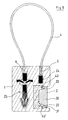
- the seal according to the invention consists of a transparent plastic body 1, the metal plate 2 is no longer embedded but inserted into the body 1 so that a part 30 of this plate 2 is free to allow more easily the action of the customs marking pliers, the other part 22 comprising a shoulder 23 as well as two orifices filled with two pins 43 and 43 ′ in material plastic integral with the body 1 and which make the plate 2 inseparable from the said body 1.
- the fixed end 5 of the steel cable 4 is taken in a metallic mass 24 embedded in the body of the seal and which makes it unbreakable unless the body 1 of the seal is destroyed.
- the free end 6 of the cable 4 is taken in a device 25 comprising a plastic tip 26 provided at its end with two fins 27 and 27 ′ which give it a harpoon shape.
- the end 40 of the cable can be frayed in the end piece 26 before molding.
- the tubular opening 7 has at its lower part an enlargement 8 of conical shape adapted to that of the end of the endpiece 26, intended to house the fins 27 and 27 ′ while preventing their removal.
- the fins 27 and 27 ′ fold back in the recessed parts 28 and 29 to then unfold in the enlargement 8.
- the cable 4 can then no longer be removed without tearing off the fins 27 and 27 ′.
- the endpiece 26 is flattened at its end 39, so that the fins 27, 27 ′ cannot rotate in their housing 8.
- the plastic body 26 can be dyed in bright color so as to make visible any attack on the seal.
- Two metal cylinders 32 and 33 are fixed to the cable 4, the end of the lower cylinder 32 being in contact with the plastic end piece 26 and a space 34 being formed between the cylinder 32 and the cylinder 33 so as to leave the exposed cable.
- the space 34 is facing two chambers 35 and 35 ′ arranged face to face and containing two plastic lugs 36 and 36 ′ arranged in housings 37 and 37 ′.
- the cylinder 33 prevents access from the outside to the lugs 36 and 36 ′ to spread them apart by means of an instrument, while the cylinder 32 has the function of destroying said lugs in the event of breaking of the seal.
- the ends 38 and 38 ′ of the lugs 36 and 36 ′ are bevelled in order to facilitate the introduction of the end piece 26 when the seal is closed.
- FIG. 5 we see in this figure a variant of the seal shown in FIGS. 3 and 4, comprising the same elements with, in addition, two additional lugs 41 and 41 ′ arranged in two housings 42 and 42 ′ formed apart and on the other side of the fixed end 5 of the cable 4, at a short distance from the metallic mass 24, this additional device helping to reinforce the security of the seal, in fact, in the event of an attempt to tear off the cable on the side of this end , the pins 41 and 41 ′ are visibly deteriorated.
- This embodiment of the seal according to the invention offers the advantage of facilitating the action of a customs clamp on the metal plate in order to affix an identification number on one of its faces.
- the other side of the plate can then receive this same number in computer bar code and an electronic chip with solar cell can also be inserted in the transparent body of the seal to allow electronic reading of this same number.
Landscapes
- Engineering & Computer Science (AREA)
- Computer Security & Cryptography (AREA)
- Physics & Mathematics (AREA)
- General Physics & Mathematics (AREA)
- Theoretical Computer Science (AREA)
- Installation Of Indoor Wiring (AREA)
- Connector Housings Or Holding Contact Members (AREA)
- Manufacture Of Macromolecular Shaped Articles (AREA)
- Organic Low-Molecular-Weight Compounds And Preparation Thereof (AREA)
- Acyclic And Carbocyclic Compounds In Medicinal Compositions (AREA)
- Laying Of Electric Cables Or Lines Outside (AREA)
- Packaging Of Annular Or Rod-Shaped Articles, Wearing Apparel, Cassettes, Or The Like (AREA)
- Food Preservation Except Freezing, Refrigeration, And Drying (AREA)
- Medical Preparation Storing Or Oral Administration Devices (AREA)
Abstract
Description
- La présente invention a pour objet un scellé infalsifiable destiné notamment aux conteneurs de tous types, tels que wagons, remorques, citernes, conteneurs maritimes ou analogues.
- On connaît le problème posé par le scellement de ces conteneurs, qui transportent d'importantes quantités de marchandises et qui se trouvent fréquemment entreposés pendant d'assez longues durées dans des cales de navire, des entrepôts ou sur des quais au cours de transports terrestres ou maritimes.
- Les différents types de scellés proposés à ce jour pour garantir leur fermeture présentent en effet l'inconvénient majeur de pouvoir donner lieu à une ouverture frauduleuse tout en conservant l'apparence de l'infalsifiabilité.
- Le problème se posait donc de mettre au point un scellé qui offre une garantie effective d'infalsifiabilité, c'est-à-dire dont l'ouverture frauduleuse ne puisse être masquée.
- La présente invention a pour but d'apporter une solution au problème ainsi posé en proposant un scellé qui offre à cet égard toutes les garanties de sécurité souhaitées.
- La présente invention a ainsi pour objet un scellé infalsifiable qui se caractérise essentiellement en ce qu'il est constitué d'un corps en matière transparente dans lequel se trouvent insérées d'une part une plaque métallique portant le sigle et le numéro d'identification du chargement et d'autre part l'extrémité d'un câble d'acier dont l'autre extrémité est destinée à être introduite dans une ouverture tubulaire pratiquée dans ledit corps et munie de moyens de fixation de ladite extrémité qui interdisent sont retrait de ladite ouverture tubulaire sauf à détruire de manière irréversible lesdits moyens de fixation.
- Conformément à l'invention, la matière transparente mise en oeuvre pour réaliser le corps du scellé selon l'invention consiste avantageusement en une résine synthétique du type polyméthacrytale, la plaque métallique pouvant être une plaque d'aluminium.
- Le câble d'acier mis en oeuvre est avantageusement constitué d'un fil d'acier torsadé impossible à recoller en cas de coupure.
- Selon un premier mode de réalisation du scellé selon l'invention, l'extrémité libre du câble d'acier est prolongée par une masse métallique comportant, à une courte distance de son extrémité, un rétrécissement tronconique terminé par une gorge circulaire formant butée, et les moyens de fixation de ladite extrémité libre, disposés dans l'ouverture tubulaire pratiquée dans le corps du scellé, consistent en un jeu de plusieurs aiguilles d'acier partiellement noyées dans le corps du scellé et dont l'extrémité débouche en oblique dans ladite ouverture tubulaire, à une courte distance de son fond, vers lequel elles sont orientées de manière à venir prendre appui sur la masse métallique à proximité de la gorge circulaire formant butée.
- Un tel dispositif permet de garantir l'impossibilité de réutilisation desdits moyens de fixation, les aiguilles étant irréversiblement détruites lorque le câble est forcé hors de son logement.
- Par ailleurs, l'ouverture tubulaire peut être prolongée latéralement, à une courte distance de son orifice de sortie, par un logement également tubulaire dont l'axe lui est perpendiculaire et qui abrite une masselotte séparée du fond de ladite ouverture par un ressort qui l'applique contre une tige disposée transversalement à l'ouverture de son logement, ladite tige étant maintenue par tout moyen approprié et étant prolongée, à celle de ses extrémités proche de la sortie de l'ouverture tubulaire, par une lame-ressort disposée en oblique et orientée vers le fond de ladite ouverture tubulaire, de manière à venir prendre appui sur le câble d'acier et à être entraînée vers l'orifice de sortie lors du retrait de ce dernier, car venant alors en prise sur la gorge circulaire ménagée sur la masse métallique qui prolonge l'extrémité dudit câble, ce qui a pour effet de libérer la masselotte qui, sous l'effet de la poussée exercée par le ressort, se déplace transversalement à l'ouverture tubulaire, venant se loger par son extrémité dans un évidement pratiqué à cet effet en regard de son logement.
- Ce dispositif permet d'empêcher la réintroduction du câble dans l'ouverture tubulaire après rupture du scellé, interdisant de ce fait toute possibilité de masquer son effraction.
- Selon un second mode de réalisation du scellé selon l'invention, l'extrémité libre du câble est prolongée par un embout de matière plastique muni d'ailettes qui lui confèrent la forme d'un harpon et qui se logent dans un élargissement en forme de cône ménagé à la base de l'ouverture tubulaire, interdisant le retrait du câble sauf à briser lesdites ailettes.
- Un dispositif complémentaire peut permettre d'accroître la sécurité d'utilisation de ce type de scellé, consistant en deux cylindres métalliques disposés au-dessus de l'embout de matière plastique et traversés par le câble, le cylindre inférieur étant au contact de l'embout de matière plastique et étant séparé du cylindre supérieur par un espace au niveau duquel, lorsque le scellé est fermé, se trouvent deux élargissements de l'ouverture tubulaire renfermant deux ergots destinés à être brisés par le cylindre inférieur en cas d'effraction du scellé, le cylindre supérieur ayant pour fonction d'empêcher l'accès de l'extérieur auxdits ergots en vue de les écarter à l'aide d'un instrument.
- L'extrémité fixe du câble du scellé selon l'invention peut être simplement noyée dans le corps de matière transparente, mais elle peut aussi être prise dans une masse métallique insérée dans le corps du scellé, ce qui rend son arrachement encore plus difficile.
- La plaque métallique du scellé selon l'invention peut d'autre part être noyée dans le corps de matière transparente, auquel cas une fenêtre pratiquée dans ce dernier permet l'apposition d'un numéro d'identification à l'aide d'une pince de douane. Elle peut également être insérée latéralement dans le corps de matière transparente où elle est maintenue solidement par tous moyens appropriés, une partie de cette plaque se trouvant libre pour permettre le marquage douanier.
- La présente invention sera mieux comprise à la lecture de la description qui suit et qui se réfère au dessin annexé, lequel en représente quelques modes de réalisation non limitatifs vis-à-vis de la portée de l'invention.
- Dans le dessin annexé :
- - la figure 1 représente une vue en perspective d'un premier mode de réalisation d'un scellé selon l'invention.
- - la figure 2a représente une vue en coupe, à plus grande échelle, de l'ouverture tubulaire du même scellé, avant sa fermeture.
- - la figure 2b représente l'ouverture tubulaire du même scellé pendant la fermeture de ce dernier.
- - la figure 2c représente l'ouverture tubulaire du même scellé après rupture de ce dernier.
- - la figure 3 représente une vue de face d'un second mode de réalisation du scellé selon l'invention.
- - la figure 4 représente une vue en coupe, à plus grande échelle, du dispositif de fermeture du même scellé.
- - la figure 5 représente en vue de face une variante de ce même scellé.
- Si on se réfère d'abord à la figure 1, on voit que le scellé selon l'invention est constitué d'un corps 1 en résine transparente dans lequel est noyée une plaque d'aluminium 2 destinée à porter à sa partie supérieure les sigle et numéro d'identification du chargement et surmontée à sa partie inférieure d'une fenêtre 3 ménagée dans ledit corps 1 de manière à permettre l'apposition d'un numéro de contrôle douanier.
- Un câble d'acier 4 est fixé par une de ses extrémités 5 dans le corps 1, dans lequel ladite extrémité 5 est noyée, son autre extrémité 6 pouvant être introduite dans une ouverture tubulaire 7 qui est décrite en détail ci-après.
- Si on se réfère à la figure 2a, on voit que l'ouverture tubulaire 7 présente à sa partie inférieure un élargissement 8 au niveau duquel débouchent des aiguilles 9 partiellement noyées dans le corps 1. A une courte distance de l'orifice 10 d'entrée de l'ouverture tubulaire 7 se trouve ménagé, perpendiculairement à l'ouverture 7, un logement cylindrique 11 abritant une masselotte 12 et un ressort 13 positionné au fond dudit logement 11. Une tige 14 est disposée devant l'ouverture du logement 11, étant logée par une de ses extrémités dans un évidement 15 ménagé à la base du logement 11 et étant maintenue au voisinage de son autre extrémité par une languette en U 16, ladite extrémité étant prolongée par une lame-ressort 17 disposée en oblique et orientée vers le fond de l'ouverture 7. La tige 14 maintient la masselotte 12 dans son logement 11, le ressort 13 étant comprimé. En regard du logement 11 se trouve ménagé un évidement cylindrique 18 de même diamètre. L'ouverture tubulaire 7 comporte, du côté du logement 11, un léger élargissement permettant d'abriter la tige 14 prolongée par la lame-ressort 17, de manière à libérer le passage pour le câble.
- Si on se réfère maintenant à la figure 2b, on retrouve sur cette figure les mêmes éléments que sur la figure 2a, complétés par le câble 4 dont l'extrémité 6 est insérée dans l'ouverture tubulaire 7, étant prolongé par une masse métallique 19 de forme approximativement cylindrique sur laquelle est ménagé, à courte distance de son extrémité, un rétrécissement tronconique 20 créant une gorge circulaire 21. Les aiguilles 9 de l'ouverture tubulaire 7 se trouvent incurvées par le câble 4, venant en appui contre la masse 19, à proximité de la gorge 21. De la même manière la lame-ressort 17 se trouve rabattue et vient en appui contre le câble 4, la tige 14 étant dans la même position qu'à la figure 2a.
- Si on se réfère enfin à la figure 2c, on voit le dispositif après retrait du câble provenant d'une effraction.
- On voit sur cette figure les aiguilles 9 détruites par l'arrachage du câble, brisées ou repliées, formant un bourrage qui rend quasi impossible le retrait du câble. Si toutefois ce retrait est accompli, le câble en sortant de l'ouverture tubulaire 7 entraîne la lame-ressort 17 de la tige 14, libérant de son logement 11 la masselotte 12 qui sous la poussée du ressort 13 vient obstruer l'ouverture tubulaire 7, venant se loger par son extrémité dans l'évidement 18, en empêchant la remise en place du câble 4.
- Ce mode de réalisation du scellé selon l'invention offre ainsi une double garantie de sécurité, ne pouvant être ouvert par aucun moyen susceptible de donner lieu à un masquage et ne pouvant reprendre après effraction son apparence de départ, du fait que le câble ne peut plus être inséré dans le logement qui lui est dévolu.
- A cet avantage s'ajoute celui inhérent au fait que le corps en matière transparente permet d'éviter une falsification des numéros portés sur la plaque d'aluminium, ce qui constitue une garantie supplémentaire de sécurité.
- Selon une variante de réalisation de ce premier mode de réalisation, la gorge circulaire ménagée dans la masse métallique qui prolonge le câble peut être réalisée de façon à créer une zone de fragilité présentant un seuil de rupture relativement bas, de manière que la masse casse au niveau de la gorge sous l'effet de la traction exercée pour arracher le câble et de la résistance opposée par les aiguilles brisées ou repliées, l'extrémité de la masse métallique pouvant alors tomber dans un logement prévu à cet effet, manifestant par transparence l'anomalie ainsi créée et servant par là même de témoin visuel de l'effraction.
- De la même manière la masselotte qui vient obturer l'ouverture tubulaire après arrachage du câble sert de témoin visuel de l'effraction, et elle peut être teintée d'une couleur vive de manière à être plus facilement repérable dans la masse du corps du scellé une fois qu'elle est sortie de son logement, lequel consiste de préférence en un tube métallique qui la rend invisible tant que le scellé n'a pas été forcé.
- Enfin la sécurité du dispositif selon l'invention peut encore être accrue par la mise en oeuvre d'une masselotte en un métal amagnétique comme l'aluminium, empêchant son bloquage dans son logement par un aimant.
- Si on se réfère ensuite aux figures 3 et 4, on voit que le scellé selon l'invention est constitué d'un corps en matière plastique transparente 1, la plaque métallique 2 se trouvant non plus noyée mais insérée dans le corps 1 de telle sorte qu'une partie 30 de cette plaque 2 se trouve libre pour permettre plus aisément l'action de la pince de marquage en douane, l'autre partie 22 comportant un épaulement 23 ainsi que deux orifices remplis par deux tétons 43 et 43′ en matière plastique solidaires du corps 1 et qui rendent la plaque 2 indissociable dudit corps 1.
- L'extrémité fixe 5 du câble d'acier 4 est prise dans une masse métallique 24 noyée dans le corps du scellé et qui la rend inarrachable sauf à détruire le corps 1 du scellé.
- L'extrémité libre 6 du câble 4 se trouve prise dans un dispositif 25 comprenant un embout de matière plastique 26 muni à son extrémité de deux ailettes 27 et 27′ qui lui donnent une forme de harpon. Pour une meilleure tenue, l'extrémité 40 du câble peut être effilochée dans l'embout 26 avant moulage.
- L'ouverture tubulaire 7 présente à sa partie inférieure un élargissement 8 de forme cônique adaptée à celle de l'extrémité de l'embout 26, destiné à abriter les ailettes 27 et 27′ en empêchant leur retrait.
- Lorsque la pièce 25 est introduite dans l'ouverture tubulaire 7 les ailettes 27 et 27′ se replient dans les parties évidées 28 et 29 pour se déplier ensuite dans l'élargissement 8. Le câble 4 ne peut alors plus être retiré sans arrachement des ailettes 27 et 27′. L'embout 26 est aplati à son extrémité 39, de manière que les ailettes 27, 27′ ne puissent pas tourner dans leur logement 8. Le corps plastique 26 peut être teinté en couleur vive de façon à rendre visible toute atteinte au scellé.
- Deux cylindres métalliques 32 et 33 sont fixés sur le câble 4, l'extrémité du cylindre inférieur 32 étant en contact avec l'embout de matière plastique 26 et un espace 34 étant ménagé entre le cylindre 32 et le cylindre 33 de manière à laisser le câble apparent.
- Lorsque le scellé est fermé l'espace 34 se trouve face à deux chambres 35 et 35′ disposées face à face et renfermant deux ergots de matière plastique 36 et 36′ disposés dans des logements 37 et 37′.
- Ainsi lors de l'introduction de l'embout 26 du câble dans l'ouverture tubulaire 7, les deux ergots 36 et 36′ s'écartent dans l'espace libre des chambres 35 et 35′ et reviennent ensuite, en raison de leur élasticité, dans l'espace 34 au voisinage de la pièce cylindrique 33.
- En cas de traction sur le câble 4 destinée à rompre le scellé les ergots 36 et 36′ seront brisés ainsi que les ailes 27 et 27′ de l'embout 26.
- Le cylindre 33 empêche d'accéder de l'extérieur aux ergots 36 et 36′ pour les écarter au moyen d'un instrument, tandis que le cylindre 32 a pour fonction de détruire lesdits ergots en cas d'effraction du scellé.
- Les extrémités 38 et 38′ des ergots 36 et 36′ sont biseautées en vue de faciliter l'introduction de l'embout 26 lors de la fermeture du scellé.
- Si on se réfère maintenant à la figure 5, on voit sur cette figure variante du scellé représenté aux figures 3 et 4, comportant les mêmes éléments avec en outre deux ergots supplémentaires 41 et 41′ disposés dans deux logements 42 et 42′ ménagés de part et d'autre de l'extrémité fixe 5 du câble 4, à courte distance de la masse métallique 24, ce dispositif supplémentaire contribuant à renforcer la sécurité du scellé en effet, en cas de tentative d'arrachement du câble du côté de cette extrémité, les ergots 41 et 41′ sont visiblement détériorés.
- Ce mode de réalisation du scellé selon l'invention offre l'avantage de faciliter l'action d'une pince de douane sur la plaque métallique afin d'apposer un numéro d'identification sur l'une de ses faces. L'autre face de la plaque peut alors recevoir ce même numéro en code barre informatique et une puce électronique avec pile solaire peut en outre être insérée dans le corps transparent du scellé pour permettre la lecture électronique de ce même numéro.
Claims (10)
Applications Claiming Priority (4)
| Application Number | Priority Date | Filing Date | Title |
|---|---|---|---|
| FR8911947 | 1989-09-08 | ||
| FR8911947A FR2651750B1 (fr) | 1989-09-08 | 1989-09-08 | Scelle infalsifiable destine notamment aux conteneurs de tous types. |
| FR9000772 | 1990-01-19 | ||
| FR909000772A FR2657331B2 (fr) | 1989-09-08 | 1990-01-19 | Scelle infalsifiable destine notamment aux conteneurs de tous types. |
Publications (2)
| Publication Number | Publication Date |
|---|---|
| EP0417022A1 true EP0417022A1 (fr) | 1991-03-13 |
| EP0417022B1 EP0417022B1 (fr) | 1994-06-08 |
Family
ID=26227549
Family Applications (1)
| Application Number | Title | Priority Date | Filing Date |
|---|---|---|---|
| EP90440078A Expired - Lifetime EP0417022B1 (fr) | 1989-09-08 | 1990-09-10 | Scellé infalsifiable destiné notamment aux conteneurs de tous types |
Country Status (4)
| Country | Link |
|---|---|
| EP (1) | EP0417022B1 (fr) |
| AT (1) | ATE107064T1 (fr) |
| DE (1) | DE69009637D1 (fr) |
| FR (1) | FR2657331B2 (fr) |
Cited By (16)
| Publication number | Priority date | Publication date | Assignee | Title |
|---|---|---|---|---|
| EP0537400A1 (fr) * | 1991-10-15 | 1993-04-21 | Securtir S.A. | Scellé infalsifiable destiné notamment aux conteneurs de tous types |
| GB2282570A (en) * | 1993-09-27 | 1995-04-12 | Ej Brooks Company | Security seal with tamper-resistant indicia. |
| FR2740595A1 (fr) * | 1995-10-27 | 1997-04-30 | Fortin Jean | Scelle en particulier pour portes de conteneurs |
| FR2742908A1 (fr) * | 1995-12-22 | 1997-06-27 | Fors France Sa | Dispositif de plombage forme par un corps et un cable propre a entourer une partie de l'article a proteger |
| US5647620A (en) * | 1994-12-22 | 1997-07-15 | Kuenzel; Rainer | Cable lock and seal device incorporating self locking feature |
| US5826447A (en) * | 1996-12-09 | 1998-10-27 | Campbell; Michael C. | Procedure for handling materials in drums and bung-plug apparatus and method therefor |
| RU2123208C1 (ru) * | 1997-08-05 | 1998-12-10 | Российский Федеральный Ядерный Центр - Всероссийский Научно-Исследовательский Институт Экспериментальной Физики | Пломбировочное устройство |
| RU2125297C1 (ru) * | 1998-04-16 | 1999-01-20 | Закрытое Акционерное Общество "Страж" | Тросовая пломба-запор |
| RU2127453C1 (ru) * | 1997-07-14 | 1999-03-10 | Закрытое Акционерное Общество "Страж" | Тросовая пломба (варианты) |
| RU2141557C1 (ru) * | 1999-02-16 | 1999-11-20 | Лажинцев Олег Аркадьевич | Тросовая пломба-запор |
| RU2404340C1 (ru) * | 2009-03-19 | 2010-11-20 | Алексей Петрович Кретов | Гибкое запорно-пломбировочное устройство |
| USD798918S1 (en) | 2015-11-25 | 2017-10-03 | Justrite Manufacturing Company, L.L.C. | Shield for puncturing device |
| US9808842B2 (en) | 2011-08-18 | 2017-11-07 | Justrite Manufacturing Company, L.L.C. | Gas evacuation system with counter |
| US9827528B2 (en) | 2015-04-01 | 2017-11-28 | Justrite Manufacturing Company, Llc | Filter for a propellant gas evacuation system |
| US9845232B2 (en) | 2014-02-17 | 2017-12-19 | Justrite Manufacturing Company, Llc | Puncturing device for aerosol containers |
| US9993764B2 (en) | 2014-04-01 | 2018-06-12 | Justrite Manufacturing Company, Llc | Filter for a propellant gas evacuation system |
Families Citing this family (1)
| Publication number | Priority date | Publication date | Assignee | Title |
|---|---|---|---|---|
| DE102005059077A1 (de) * | 2005-12-10 | 2007-06-14 | Rudolf Held Gmbh & Co. Kg | Kunststoff-Sicherheitsplombe |
Citations (3)
| Publication number | Priority date | Publication date | Assignee | Title |
|---|---|---|---|---|
| GB1516783A (en) * | 1976-10-27 | 1978-07-05 | Brammall Inc | Fastening means |
| US4183566A (en) * | 1978-03-06 | 1980-01-15 | Hercules Industries, Inc. | Seal lock |
| US4836590A (en) * | 1988-04-27 | 1989-06-06 | E. J. Brooks Company | Security seal with tampering indicator |
-
1990
- 1990-01-19 FR FR909000772A patent/FR2657331B2/fr not_active Expired - Lifetime
- 1990-09-10 DE DE69009637T patent/DE69009637D1/de not_active Expired - Lifetime
- 1990-09-10 EP EP90440078A patent/EP0417022B1/fr not_active Expired - Lifetime
- 1990-09-10 AT AT90440078T patent/ATE107064T1/de not_active IP Right Cessation
Patent Citations (3)
| Publication number | Priority date | Publication date | Assignee | Title |
|---|---|---|---|---|
| GB1516783A (en) * | 1976-10-27 | 1978-07-05 | Brammall Inc | Fastening means |
| US4183566A (en) * | 1978-03-06 | 1980-01-15 | Hercules Industries, Inc. | Seal lock |
| US4836590A (en) * | 1988-04-27 | 1989-06-06 | E. J. Brooks Company | Security seal with tampering indicator |
Cited By (18)
| Publication number | Priority date | Publication date | Assignee | Title |
|---|---|---|---|---|
| EP0537400A1 (fr) * | 1991-10-15 | 1993-04-21 | Securtir S.A. | Scellé infalsifiable destiné notamment aux conteneurs de tous types |
| GB2282570A (en) * | 1993-09-27 | 1995-04-12 | Ej Brooks Company | Security seal with tamper-resistant indicia. |
| GB2282570B (en) * | 1993-09-27 | 1997-07-16 | Brooks Co E J | Improvements relating to security seals |
| US5647620A (en) * | 1994-12-22 | 1997-07-15 | Kuenzel; Rainer | Cable lock and seal device incorporating self locking feature |
| FR2740595A1 (fr) * | 1995-10-27 | 1997-04-30 | Fortin Jean | Scelle en particulier pour portes de conteneurs |
| FR2742908A1 (fr) * | 1995-12-22 | 1997-06-27 | Fors France Sa | Dispositif de plombage forme par un corps et un cable propre a entourer une partie de l'article a proteger |
| US5826447A (en) * | 1996-12-09 | 1998-10-27 | Campbell; Michael C. | Procedure for handling materials in drums and bung-plug apparatus and method therefor |
| RU2127453C1 (ru) * | 1997-07-14 | 1999-03-10 | Закрытое Акционерное Общество "Страж" | Тросовая пломба (варианты) |
| RU2123208C1 (ru) * | 1997-08-05 | 1998-12-10 | Российский Федеральный Ядерный Центр - Всероссийский Научно-Исследовательский Институт Экспериментальной Физики | Пломбировочное устройство |
| RU2125297C1 (ru) * | 1998-04-16 | 1999-01-20 | Закрытое Акционерное Общество "Страж" | Тросовая пломба-запор |
| RU2141557C1 (ru) * | 1999-02-16 | 1999-11-20 | Лажинцев Олег Аркадьевич | Тросовая пломба-запор |
| RU2404340C1 (ru) * | 2009-03-19 | 2010-11-20 | Алексей Петрович Кретов | Гибкое запорно-пломбировочное устройство |
| US9808842B2 (en) | 2011-08-18 | 2017-11-07 | Justrite Manufacturing Company, L.L.C. | Gas evacuation system with counter |
| US9845232B2 (en) | 2014-02-17 | 2017-12-19 | Justrite Manufacturing Company, Llc | Puncturing device for aerosol containers |
| US10618791B2 (en) | 2014-02-17 | 2020-04-14 | Justrite Manufacturing Company, Llc | Puncturing device for aerosol containers |
| US9993764B2 (en) | 2014-04-01 | 2018-06-12 | Justrite Manufacturing Company, Llc | Filter for a propellant gas evacuation system |
| US9827528B2 (en) | 2015-04-01 | 2017-11-28 | Justrite Manufacturing Company, Llc | Filter for a propellant gas evacuation system |
| USD798918S1 (en) | 2015-11-25 | 2017-10-03 | Justrite Manufacturing Company, L.L.C. | Shield for puncturing device |
Also Published As
| Publication number | Publication date |
|---|---|
| EP0417022B1 (fr) | 1994-06-08 |
| FR2657331A2 (fr) | 1991-07-26 |
| DE69009637D1 (de) | 1994-07-14 |
| ATE107064T1 (de) | 1994-06-15 |
| FR2657331B2 (fr) | 1992-05-22 |
Similar Documents
| Publication | Publication Date | Title |
|---|---|---|
| EP0417022B1 (fr) | Scellé infalsifiable destiné notamment aux conteneurs de tous types | |
| EP1511909B1 (fr) | Scelle multi-usage a serrure et procede de fabrication d'un scelle multi-usage | |
| FR2485645A1 (fr) | Verrou temporaire inviolable pour pompe de distribution | |
| EP4326638A1 (fr) | Colis comprenant un scellé | |
| EP0105796B1 (fr) | Plaquette d'identité, notamment pour le bétail | |
| FR2816434A1 (fr) | Dispositif de scelle a puce electronique | |
| EP0310597A1 (fr) | Joint. | |
| FR2817585A1 (fr) | Dispositif de blocage d'un verin de porte en position ouverte de la porte | |
| FR2651750A1 (fr) | Scelle infalsifiable destine notamment aux conteneurs de tous types. | |
| EP0283402B1 (fr) | Dispositif de scellés | |
| FR2630772A1 (fr) | Scelle de haute securite, en particulier pour porte de wagon ou de conteneur | |
| EP3984906B1 (fr) | Bouchon à vis destiné à rester attaché à un récipient après ouverture et pouvant être maintenu dans une position d´ ouverture | |
| EP1030008B1 (fr) | Dispositif de protection du cylindre d'une serrure de porte | |
| WO2015091597A1 (fr) | Dispositif d'obturation d'un recipient presentant un col | |
| BE1003318A3 (fr) | Sceau de securite. | |
| FR2881400A1 (fr) | Scelle tige securise pour les conteneurs | |
| WO2023198492A1 (fr) | Colis comprenant un scellé secable et scellé | |
| FR2865190A1 (fr) | Dispositif de securisation de tubes | |
| FR2884502A1 (fr) | Dispositif d'inviolabilite pour conteneur | |
| FR2746534A1 (fr) | Systeme de badge | |
| WO2006018574A2 (fr) | Procede de fabrication d'un dispositif de fermeture marque et dispositif de fermeture. | |
| EP0951361A1 (fr) | Echantillon de parfum liquide | |
| FR2649077A1 (fr) | Obturateur de bonde | |
| EP0968646A1 (fr) | Pendentif ou boucle d'oreille inviolable pour le marquage des animaux | |
| FR2663360A1 (fr) | Organe de fermeture inviolable pour sac de transport de fonds ou de valeurs, ou objets analogues. |
Legal Events
| Date | Code | Title | Description |
|---|---|---|---|
| PUAI | Public reference made under article 153(3) epc to a published international application that has entered the european phase |
Free format text: ORIGINAL CODE: 0009012 |
|
| AK | Designated contracting states |
Kind code of ref document: A1 Designated state(s): AT BE CH DE DK ES GB GR IT LI LU NL SE |
|
| 17P | Request for examination filed |
Effective date: 19910912 |
|
| 17Q | First examination report despatched |
Effective date: 19930701 |
|
| GRAA | (expected) grant |
Free format text: ORIGINAL CODE: 0009210 |
|
| AK | Designated contracting states |
Kind code of ref document: B1 Designated state(s): AT BE CH DE DK ES GB GR IT LI LU NL SE |
|
| PG25 | Lapsed in a contracting state [announced via postgrant information from national office to epo] |
Ref country code: IT Free format text: LAPSE BECAUSE OF FAILURE TO SUBMIT A TRANSLATION OF THE DESCRIPTION OR TO PAY THE FEE WITHIN THE PRE;WARNING: LAPSES OF ITALIAN PATENTS WITH EFFECTIVE DATE BEFORE 2007 MAY HAVE OCCURRED AT ANY TIME BEFORE 2007. THE CORRECT EFFECTIVE DATE MAY BE DIFFERENT FROM THE ONE RECORDED.SCRIBED TIME-LIMIT Effective date: 19940608 Ref country code: ES Free format text: THE PATENT HAS BEEN ANNULLED BY A DECISION OF A NATIONAL AUTHORITY Effective date: 19940608 Ref country code: GB Effective date: 19940608 Ref country code: NL Effective date: 19940608 Ref country code: DK Effective date: 19940608 Ref country code: GR Free format text: LAPSE BECAUSE OF FAILURE TO SUBMIT A TRANSLATION OF THE DESCRIPTION OR TO PAY THE FEE WITHIN THE PRESCRIBED TIME-LIMIT Effective date: 19940608 Ref country code: AT Effective date: 19940608 |
|
| RAP1 | Party data changed (applicant data changed or rights of an application transferred) |
Owner name: SECURTIR S.A. |
|
| REF | Corresponds to: |
Ref document number: 107064 Country of ref document: AT Date of ref document: 19940615 Kind code of ref document: T |
|
| REF | Corresponds to: |
Ref document number: 69009637 Country of ref document: DE Date of ref document: 19940714 |
|
| PG25 | Lapsed in a contracting state [announced via postgrant information from national office to epo] |
Ref country code: SE Effective date: 19940908 |
|
| PG25 | Lapsed in a contracting state [announced via postgrant information from national office to epo] |
Ref country code: DE Effective date: 19940909 |
|
| PGFP | Annual fee paid to national office [announced via postgrant information from national office to epo] |
Ref country code: LU Payment date: 19941001 Year of fee payment: 5 |
|
| PGFP | Annual fee paid to national office [announced via postgrant information from national office to epo] |
Ref country code: CH Payment date: 19941014 Year of fee payment: 5 |
|
| NLV1 | Nl: lapsed or annulled due to failure to fulfill the requirements of art. 29p and 29m of the patents act | ||
| GBV | Gb: ep patent (uk) treated as always having been void in accordance with gb section 77(7)/1977 [no translation filed] |
Effective date: 19940608 |
|
| PLBE | No opposition filed within time limit |
Free format text: ORIGINAL CODE: 0009261 |
|
| STAA | Information on the status of an ep patent application or granted ep patent |
Free format text: STATUS: NO OPPOSITION FILED WITHIN TIME LIMIT |
|
| 26N | No opposition filed | ||
| PG25 | Lapsed in a contracting state [announced via postgrant information from national office to epo] |
Ref country code: LU Free format text: LAPSE BECAUSE OF NON-PAYMENT OF DUE FEES Effective date: 19950910 |
|
| PG25 | Lapsed in a contracting state [announced via postgrant information from national office to epo] |
Ref country code: LI Effective date: 19950930 Ref country code: CH Effective date: 19950930 |
|
| PGFP | Annual fee paid to national office [announced via postgrant information from national office to epo] |
Ref country code: BE Payment date: 19951009 Year of fee payment: 6 |
|
| REG | Reference to a national code |
Ref country code: CH Ref legal event code: PL |
|
| PG25 | Lapsed in a contracting state [announced via postgrant information from national office to epo] |
Ref country code: BE Effective date: 19960930 |
|
| BERE | Be: lapsed |
Owner name: S.A. SECURTIR Effective date: 19960930 |