EP0417262B1 - Hydraulische ramme - Google Patents
Hydraulische ramme Download PDFInfo
- Publication number
- EP0417262B1 EP0417262B1 EP90906251A EP90906251A EP0417262B1 EP 0417262 B1 EP0417262 B1 EP 0417262B1 EP 90906251 A EP90906251 A EP 90906251A EP 90906251 A EP90906251 A EP 90906251A EP 0417262 B1 EP0417262 B1 EP 0417262B1
- Authority
- EP
- European Patent Office
- Prior art keywords
- valve
- chamber
- bell
- clapper
- ram
- Prior art date
- Legal status (The legal status is an assumption and is not a legal conclusion. Google has not performed a legal analysis and makes no representation as to the accuracy of the status listed.)
- Expired - Lifetime
Links
- XLYOFNOQVPJJNP-UHFFFAOYSA-N water Substances O XLYOFNOQVPJJNP-UHFFFAOYSA-N 0.000 claims abstract description 33
- 238000013016 damping Methods 0.000 claims description 4
- 238000005192 partition Methods 0.000 claims description 4
- 238000001914 filtration Methods 0.000 claims description 3
- 238000011144 upstream manufacturing Methods 0.000 claims description 3
- 238000004873 anchoring Methods 0.000 claims 1
- 230000035939 shock Effects 0.000 abstract description 2
- 239000006096 absorbing agent Substances 0.000 abstract 1
- 230000004888 barrier function Effects 0.000 abstract 1
- 239000012858 resilient material Substances 0.000 abstract 1
- 230000003247 decreasing effect Effects 0.000 description 1
- 238000005553 drilling Methods 0.000 description 1
- 238000007689 inspection Methods 0.000 description 1
- 239000007788 liquid Substances 0.000 description 1
- 238000000926 separation method Methods 0.000 description 1
Images

Classifications
-
- F—MECHANICAL ENGINEERING; LIGHTING; HEATING; WEAPONS; BLASTING
- F04—POSITIVE - DISPLACEMENT MACHINES FOR LIQUIDS; PUMPS FOR LIQUIDS OR ELASTIC FLUIDS
- F04F—PUMPING OF FLUID BY DIRECT CONTACT OF ANOTHER FLUID OR BY USING INERTIA OF FLUID TO BE PUMPED; SIPHONS
- F04F7/00—Pumps displacing fluids by using inertia thereof, e.g. by generating vibrations therein
- F04F7/02—Hydraulic rams
Definitions
- the present invention relates to an improved hydraulic ram.
- Hydraulic rams have been known for a very long time. These are water lifting devices using the shock in a suddenly closed pipe (water hammer) to force part of the liquid mass to rise to an altitude greater than the height of fall.
- Document US-A-1 364 617 discloses a hydraulic cylinder system using the ram principle and comprising, in particular, a bell provided with a ball valve system.
- this system does not have a chamber with a valve escape pipe and said bell is supplied with quantities of water which are discharged into the water pipe by a rocking system at the top of said pipe, if although such a system is completely incapable of raising the water above the starting level.
- document US-A-2 424 108 also discloses a hydraulic ram, but which is not designed to raise water, but to create high hydraulic pressures at high frequency, usable for example in the oil drilling or geophysical prospecting.
- the object of the invention is to improve the hydraulic water lifting rams by improving in particular the yield.
- the subject of the invention is a hydraulic ram of the type comprising a chamber, a water inlet pipe, a leakage pipe provided with a valve and a bell communicating with said chamber by means of a valve system consisting of a plurality of individual valves in parallel, of the ball type, each capable of closing a passage orifice, said bell being provided with a water delivery outlet, characterized in that the valve balls are each contained with a seat formed in a wall separating said chamber from said bell, by means of dividing partitions and a perforated bottom plate and in that the leakage duct is arranged vertically, under the ram chamber and the valve thereof has a vertical axis extending in the chamber and mounted sliding in a fixed bearing being constantly recalled and elastically in the high opening position of the valve, while said valve further comprises a damping member for the end of the down travel.
- the leakage duct is arranged vertically, under the ram chamber and the valve of the latter has a vertical axis extending in the chamber and mounted sliding in a fixed bearing being constantly and elastically returned to the high valve opening position, however, that said valve further comprises a damping member for the end-of-travel stroke.
- said valve is placed in a venturi-shaped duct, slightly upstream of the smallest section, a rubber washer being provided at the level of contact between the valve and its seat.
- a filtering grid is interposed between the chamber of the ram and the bell so as to tangent the water inlet pipe.
- the water inlet conduit has a section which widens in the direction of the ram chamber and is formed by two half-conduits provided with lateral fixing flanges superimposed in the joint plane of the half ducts, said flanges being integral with ram lugs in an appropriate fixing structure.
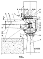
- the ram shown in the drawings comprises a cylindrical chamber 1 with a vertical axis, provided with a horizontal water inlet duct 2, a vertical leakage duct 3 disposed below the chamber 1 and with a bell cylindrical 4 disposed above the chamber 1 and provided with a connection 5 for water discharge.
- a valve system consisting of a plurality of ball-shaped valves 6 arranged in parallel each opposite a circular orifice 7 which it is likely to clog.
- the orifices or seats 7 are formed in a relatively thick plate 8 fixed in the joint plane of the bell 4 and of the chamber 1.
- the balls 6 are arranged on the side of the plate 8 opposite to the chamber 1. Each ball has a certain degree of freedom so as to be able to close its seat or, on the contrary, move away from this enough to let through a certain flow of water.
- each ball 6 is confined in a space 9 delimited by dividing partitions 10 and a perforated rear plate 11 and for example pierced with a multitude of holes (not shown).
- the passage sections 12 in the latter are in the form of a venturi, the seat itself 13 of each ball 6 being in the approximate shape of a truncated cone .
- fifty balls 6 with a diameter of the order of 70 mm can be provided.
- the balls 6 are advantageously made of rubber or the like in order to limit the noise of impacts against the walls and plate 8, 10, 11.
- a grid 14 of separation between the chamber 1 and the tank 4 intended to filter the water is disposed in the chamber 1, in the vicinity of the plate 8, in the chamber 1, in the vicinity of the plate 8, is disposed a grid 14 of separation between the chamber 1 and the tank 4 intended to filter the water, this grid 14 being arranged in the extension of the conduit 2 which it tangents substantially at the level of the upper generator.
- valve with a vertical axis coaxial with the leakage conduit 3.
- This valve comprises a shutter member 15 of generally frustoconical shape, capable of bearing against an annular seat 16 carried by the conduit 3. More specifically , this duct has a general form of venturi with a section of minimum diameter immediately downstream of said seat 16.
- a ring 17 of rubber or the like is attached to the member 15 in line with the contact area.
- the part 18 of the conduit 3 which is widening forms a diffuser.
- the shutter member 15 is fixed to the end of a vertical axis 19 slidably mounted in a sleeve 20 fixed by arms 21 to the wall of the ram chamber.
- the member 15 is constantly reminded in the high position, at a distance from the seat 16, by a spring 22, while at the end of the valve lowering stroke, a damping member, such as a Belleville washer 23 for example, is interposed between the sleeve 20 and the end of the axis 19.
- a damping member such as a Belleville washer 23 for example
- chamber 1 The interior of chamber 1 is accessible via a side inspection hatch 24.
- the interior of the bell 4 is accessible via a manhole 25.
- the water inlet duct 2 consists of two superposed half-ducts 2a, 2b and provided with lateral flanges 26 for fixing the half-ducts and for fixing the ram with two legs or lateral anchor plates 27, themselves anchored in a concrete block 28 or in any appropriate fixing structure of the ram.
- the conduit 2 widens slightly in section in the direction of the chamber 1.
- the flow of water in the vicinity of the shutter member 15 causes the speed to accelerate, closing the valve (low position shown in Figure 1).
- the shutter member 15 returns to the upper position under the action of the spring 22 which immediately creates a new leak at the valve and the cycle begins again.
- the flow yield is further improved by the shape of the inlet duct 2 and by that of the rejection duct 3 in a venturi.
- the filtering grid 14 is particularly efficient and reliable because it self-cleans automatically by the intermittent scanning provided by the water following the opening of the valve 15, this grid having its lower face in the extension of the upper generator of conduit 2.
- the invention is obviously not limited to the embodiment shown and described above but on the contrary covers all the variants thereof, in particular as regards the shapes, dimensions and arrangement of the valve members constituted by the balls 6 which can be replaced by any body likely to act as a valve under the same conditions.
- the means (partitions 10, 11) for containing each ball 6 or valve member or the like can also be replaced by other means fulfilling the same function of retaining the balls while allowing easy passage of the water in a position remote from the valves opposite their seat.
Landscapes
- Engineering & Computer Science (AREA)
- Mechanical Engineering (AREA)
- General Engineering & Computer Science (AREA)
- Pipe Accessories (AREA)
- Check Valves (AREA)
- Forklifts And Lifting Vehicles (AREA)
- Details Of Valves (AREA)
- Multiple-Way Valves (AREA)
- Saccharide Compounds (AREA)
- Placing Or Removing Of Piles Or Sheet Piles, Or Accessories Thereof (AREA)
- Stored Programmes (AREA)
- Glass Compositions (AREA)
- Surgical Instruments (AREA)
- Switches With Compound Operations (AREA)
- Lubricants (AREA)
Claims (4)
- Hydraulische Ramme des Typs umfassend eine Kammer (1), eine Wasserzuführleitung (2), eine Auslaßleitung (3) versehen mit einem Ventilkörper (15) und eine Glocke (4), die mit besagter Kammer (1) unter Zwischenschaltung eines Ventilsystems verbunden ist, das durch eine Vielzahl von einzelnen, parallel geschalteten Kugelventilen (6), geeignet zum Verschließen jeweils einer Durchtrittsöffnung (7), gebildet ist, wobei besagte Glocke mit einem Stauwasseraustritt (5) versehen ist, dadurch gekennzeichnet, daß die Kugeln der Ventile (6) gegenüber jeweils einem Sitz (13), der in einer besagte Kammer (1) von besagter Glocke (4) trennenden Wandung (8) ausgebildet ist, unter Zwischenschaltung von Trennwänden (10) und einer durchbrochenen Bodenplatte (11) gehalten sind und daß die Auslaßleitung (3) vertikal unter der Kammer (1) der Ramme angeordnet ist und der Ventilkörper (15) von dieser einen vertikalen Schaft (19) aufweist, der sich in die Kammmer erstreckt und verschiebbar in einem feststehenden Lager (20) so montiert ist, daß er beständig und elastisch in eine obere Öffnungsposition vorgespannt ist, wobei jedoch besagter Ventilkörper (15) zudem ein Element (23) zum Dämpfen des Endes des Abwärtshubs aufweist.
- Hydraulische Ramme nach Anspruch 1, dadurch gekennzeichnet, daß besagter Ventilkörper (15) in einer venturiartigen Leitung (3) etwas oberhalb des engsten Querschnitts angeordnet ist, wobei ein Kautschukring (17) im Kontaktbereich zwischen dem Ventilkörper (15) und seinem Sitz (16) vorgesehen ist.
- Hydraulische Ramme nach Anspruch 1 oder 2, dadurch gekennzeichnet, daß ein Filterrost (14) zwischen der Kammer (1) der Ramme und der Glocke (4) tangential zur Wassereintrittsleitung (2) angeordnet ist.
- Hydraulische Ramme nach einem der Ansprüche 1 bis 3, dadurch gekennzeichnet, daß die Wassereintrittsleitung (2) einen Abschnitt aufweist, der sich in Richtung zur Kammer (1) der Ramme vergrößert und durch zwei Halbleitungen (2a, 2b) gebildet ist, die mit übereinander in der Verbindungsebene der Halbleitungen angeordneten seitlichen Befestigungsflanschen (26) versehen ist, die mit Füßen (27) zum Verankern der Ramme in einer geeigneten Befestigungsstruktur (28) fest verbunden sind.
Applications Claiming Priority (3)
| Application Number | Priority Date | Filing Date | Title |
|---|---|---|---|
| FR8904492A FR2645214B1 (fr) | 1989-04-03 | 1989-04-03 | Belier hydraulique |
| FR8904492 | 1989-04-03 | ||
| PCT/FR1990/000231 WO1990012211A1 (fr) | 1989-04-03 | 1990-04-03 | Belier hydraulique |
Publications (2)
| Publication Number | Publication Date |
|---|---|
| EP0417262A1 EP0417262A1 (de) | 1991-03-20 |
| EP0417262B1 true EP0417262B1 (de) | 1994-07-27 |
Family
ID=9380419
Family Applications (1)
| Application Number | Title | Priority Date | Filing Date |
|---|---|---|---|
| EP90906251A Expired - Lifetime EP0417262B1 (de) | 1989-04-03 | 1990-04-03 | Hydraulische ramme |
Country Status (8)
| Country | Link |
|---|---|
| US (1) | US5102303A (de) |
| EP (1) | EP0417262B1 (de) |
| AT (1) | ATE109249T1 (de) |
| CA (1) | CA2030549A1 (de) |
| DE (1) | DE69011019D1 (de) |
| FR (1) | FR2645214B1 (de) |
| OA (1) | OA09276A (de) |
| WO (1) | WO1990012211A1 (de) |
Families Citing this family (3)
| Publication number | Priority date | Publication date | Assignee | Title |
|---|---|---|---|---|
| ATE164427T1 (de) * | 1993-11-29 | 1998-04-15 | Florian Schlumpf | Einrichtung zum fördern flüssiger medien |
| US5549252A (en) * | 1994-07-18 | 1996-08-27 | Industrial Sound Technologies, Inc. | Water-hammer actuated crusher |
| US20130062371A1 (en) * | 2011-09-12 | 2013-03-14 | James B. Wolff | System and method for creating a venturi effect within an orifice |
Family Cites Families (5)
| Publication number | Priority date | Publication date | Assignee | Title |
|---|---|---|---|---|
| FR370727A (fr) * | 1906-10-24 | 1907-02-18 | Niagara Hydraulic Engine C | Bélier hydraulique |
| FR414007A (fr) * | 1909-06-08 | 1910-08-24 | Gelly Et Cie | Appareil hydraulique à chocs pour l'élévation de l'eau ou de tous autres liquides |
| US1364617A (en) * | 1920-04-05 | 1921-01-04 | John C Daynix | Hydrokinetic mechanism |
| US2424108A (en) * | 1943-05-31 | 1947-07-15 | Shell Dev | Hydraulic ram system |
| GB803966A (en) * | 1956-08-02 | 1958-11-05 | Teruichi Yamaguchi | Improvements in or relating to hydraulic rams |
-
1989
- 1989-04-03 FR FR8904492A patent/FR2645214B1/fr not_active Expired - Lifetime
-
1990
- 1990-04-03 EP EP90906251A patent/EP0417262B1/de not_active Expired - Lifetime
- 1990-04-03 AT AT90906251T patent/ATE109249T1/de not_active IP Right Cessation
- 1990-04-03 CA CA002030549A patent/CA2030549A1/fr not_active Abandoned
- 1990-04-03 DE DE69011019T patent/DE69011019D1/de not_active Expired - Lifetime
- 1990-04-03 US US07/613,648 patent/US5102303A/en not_active Expired - Fee Related
- 1990-04-03 WO PCT/FR1990/000231 patent/WO1990012211A1/fr not_active Ceased
- 1990-12-03 OA OA59909A patent/OA09276A/xx unknown
Also Published As
| Publication number | Publication date |
|---|---|
| ATE109249T1 (de) | 1994-08-15 |
| EP0417262A1 (de) | 1991-03-20 |
| CA2030549A1 (fr) | 1990-10-04 |
| DE69011019D1 (de) | 1994-09-01 |
| US5102303A (en) | 1992-04-07 |
| FR2645214A1 (fr) | 1990-10-05 |
| FR2645214B1 (fr) | 1992-11-27 |
| OA09276A (fr) | 1992-08-31 |
| WO1990012211A1 (fr) | 1990-10-18 |
Similar Documents
| Publication | Publication Date | Title |
|---|---|---|
| EP0249558B1 (de) | Klappe zum automatischen Regulieren des Niveaus | |
| AU2023200153A9 (en) | Large-flow floor drain having cup-shaped inner container | |
| FR2788258A1 (fr) | Limiteur de remplissage pour cuve de stockage d'un liquide | |
| EP0417262A1 (de) | Hydraulische ramme. | |
| EP3276159B1 (de) | Stromerzeugungsanlage | |
| EP0065899B1 (de) | Wasserklosett mit mechanischer Entleerung und mit einem zugänglichen und demontierbaren Entleerungszimmer im Klosettbecken | |
| CH637189A5 (fr) | Dispositif amortisseur de pulsations. | |
| WO1995033102A1 (fr) | Equipement pour le remplissage et le vidage des reservoirs de chasse de wc | |
| FR2476790A1 (fr) | Limiteur de remplissage pour cuves de stockage de fluide | |
| FR2654761A1 (fr) | Dispositif de chasse pendulaire. | |
| FR2659099A1 (fr) | Perfectionnements apportes aux systemes automatiques d'injection d'air utilises dans les dechargeurs hydropneumatiques de citernes de water-closets. | |
| CN214090272U (zh) | 一种市政道路排水装置 | |
| FR2545886A1 (fr) | Pompe de puits comprenant une tige de piston destinee a etre actionnee par une eolienne | |
| FR2654758A1 (fr) | Dispositif de chasse pendulaire et de repartition de liquide. | |
| FR2653465A1 (fr) | Dispositif d'alimentation en eau notamment pour reservoir de w.c.. | |
| FR2914660A1 (fr) | Dispositif de chasse et systeme d'epuration pour eaux usees | |
| BE568841A (de) | ||
| KR100280074B1 (ko) | 절수형 수도꼭지 | |
| FR2860270A1 (fr) | Dispositif pour elever l'eau de la mer a un barrage. | |
| WO2025088287A1 (fr) | Pompe a dosage proportionnel et procede de dosage associe | |
| BE353231A (de) | ||
| BE666014A (de) | ||
| BE347539A (de) | ||
| CH522157A (fr) | Soupape | |
| FR2573622A1 (fr) | Urinoir pour animaux |
Legal Events
| Date | Code | Title | Description |
|---|---|---|---|
| PUAI | Public reference made under article 153(3) epc to a published international application that has entered the european phase |
Free format text: ORIGINAL CODE: 0009012 |
|
| AK | Designated contracting states |
Kind code of ref document: A1 Designated state(s): AT BE CH DE DK ES GB IT LI LU NL SE |
|
| 17P | Request for examination filed |
Effective date: 19910411 |
|
| 17Q | First examination report despatched |
Effective date: 19920901 |
|
| GRAA | (expected) grant |
Free format text: ORIGINAL CODE: 0009210 |
|
| AK | Designated contracting states |
Kind code of ref document: B1 Designated state(s): AT BE CH DE DK ES GB IT LI LU NL SE |
|
| PG25 | Lapsed in a contracting state [announced via postgrant information from national office to epo] |
Ref country code: IT Free format text: LAPSE BECAUSE OF FAILURE TO SUBMIT A TRANSLATION OF THE DESCRIPTION OR TO PAY THE FEE WITHIN THE PRE;WARNING: LAPSES OF ITALIAN PATENTS WITH EFFECTIVE DATE BEFORE 2007 MAY HAVE OCCURRED AT ANY TIME BEFORE 2007. THE CORRECT EFFECTIVE DATE MAY BE DIFFERENT FROM THE ONE RECORDED.SCRIBED TIME-LIMIT Effective date: 19940727 Ref country code: ES Free format text: THE PATENT HAS BEEN ANNULLED BY A DECISION OF A NATIONAL AUTHORITY Effective date: 19940727 Ref country code: NL Effective date: 19940727 Ref country code: AT Effective date: 19940727 Ref country code: DK Effective date: 19940727 Ref country code: GB Effective date: 19940727 |
|
| REF | Corresponds to: |
Ref document number: 109249 Country of ref document: AT Date of ref document: 19940815 Kind code of ref document: T |
|
| REF | Corresponds to: |
Ref document number: 69011019 Country of ref document: DE Date of ref document: 19940901 |
|
| PG25 | Lapsed in a contracting state [announced via postgrant information from national office to epo] |
Ref country code: SE Effective date: 19941027 |
|
| PG25 | Lapsed in a contracting state [announced via postgrant information from national office to epo] |
Ref country code: DE Effective date: 19941028 |
|
| NLV1 | Nl: lapsed or annulled due to failure to fulfill the requirements of art. 29p and 29m of the patents act | ||
| GBV | Gb: ep patent (uk) treated as always having been void in accordance with gb section 77(7)/1977 [no translation filed] |
Effective date: 19940727 |
|
| PG25 | Lapsed in a contracting state [announced via postgrant information from national office to epo] |
Ref country code: LI Effective date: 19950430 Ref country code: BE Effective date: 19950430 Ref country code: LU Free format text: LAPSE BECAUSE OF NON-PAYMENT OF DUE FEES Effective date: 19950430 Ref country code: CH Effective date: 19950430 |
|
| PLBE | No opposition filed within time limit |
Free format text: ORIGINAL CODE: 0009261 |
|
| STAA | Information on the status of an ep patent application or granted ep patent |
Free format text: STATUS: NO OPPOSITION FILED WITHIN TIME LIMIT |
|
| 26N | No opposition filed | ||
| BERE | Be: lapsed |
Owner name: GOBAUD MICHEL Effective date: 19950430 |
|
| REG | Reference to a national code |
Ref country code: CH Ref legal event code: PL |
|
| REG | Reference to a national code |
Ref country code: CH Ref legal event code: AUV Free format text: LE BREVET CI-DESSUS EST TOMBE EN DECHEANCE, FAUTE DE PAIEMENT, DE LA 6E ANNUITE. |