EP0417373A1 - Système de transmission pour la rotation d'arbres d'enroulement de volets roulants, de portes roulantes et similaires - Google Patents
Système de transmission pour la rotation d'arbres d'enroulement de volets roulants, de portes roulantes et similaires Download PDFInfo
- Publication number
- EP0417373A1 EP0417373A1 EP89500089A EP89500089A EP0417373A1 EP 0417373 A1 EP0417373 A1 EP 0417373A1 EP 89500089 A EP89500089 A EP 89500089A EP 89500089 A EP89500089 A EP 89500089A EP 0417373 A1 EP0417373 A1 EP 0417373A1
- Authority
- EP
- European Patent Office
- Prior art keywords
- piston
- shaft
- rod
- movement
- rotating shafts
- Prior art date
- Legal status (The legal status is an assumption and is not a legal conclusion. Google has not performed a legal analysis and makes no representation as to the accuracy of the status listed.)
- Withdrawn
Links
- 230000005540 biological transmission Effects 0.000 title claims abstract description 25
- 238000004804 winding Methods 0.000 title claims abstract description 4
- 230000007246 mechanism Effects 0.000 claims abstract 2
- 239000012530 fluid Substances 0.000 claims description 9
- 230000009365 direct transmission Effects 0.000 claims 1
- 238000010348 incorporation Methods 0.000 abstract 1
- XLYOFNOQVPJJNP-UHFFFAOYSA-N water Substances O XLYOFNOQVPJJNP-UHFFFAOYSA-N 0.000 description 4
- 238000006243 chemical reaction Methods 0.000 description 1
- 230000008878 coupling Effects 0.000 description 1
- 238000010168 coupling process Methods 0.000 description 1
- 238000005859 coupling reaction Methods 0.000 description 1
- 230000002093 peripheral effect Effects 0.000 description 1
- 230000000630 rising effect Effects 0.000 description 1
- 238000005096 rolling process Methods 0.000 description 1
Images

Classifications
-
- E—FIXED CONSTRUCTIONS
- E06—DOORS, WINDOWS, SHUTTERS, OR ROLLER BLINDS IN GENERAL; LADDERS
- E06B—FIXED OR MOVABLE CLOSURES FOR OPENINGS IN BUILDINGS, VEHICLES, FENCES OR LIKE ENCLOSURES IN GENERAL, e.g. DOORS, WINDOWS, BLINDS, GATES
- E06B9/00—Screening or protective devices for wall or similar openings, with or without operating or securing mechanisms; Closures of similar construction
- E06B9/56—Operating, guiding or securing devices or arrangements for roll-type closures; Spring drums; Tape drums; Counterweighting arrangements therefor
- E06B9/68—Operating devices or mechanisms, e.g. with electric drive
Definitions
- the invention relates to a transmission system for rotating shafts.
- the rotating shaft is either provided with a drum on which the blinds are wound or serves as a drive roller for a transmission for the folding of a door divided into articulated portions.
- This circuit comprises a press.When the press is operated, its force is multiplied and transmitted to a piston which moves the rod thereof linearly. This linear movement is converted by appropriate transmis sion means into a rotating movement of the shaft.
- Said transmission means are formed by a cable which is attached to and wound round the shaft at one end and attached to the piston rod at the other end. When the rod is moved, it pulls the cable, unwinding it, thereby rotating the shaft.
- a chain may also be used instead of the cable.
- the chain wraps round half a circular toothed means of the shaft and is attached at one end to the piston rod and will cause the shaft to rotate when the rod pulls on the chain.
- toothing may be cut on the piston rod and the latter may be engaged directly but perpendicularly with a peripheral toothing cut on the rotating shaft, whereby this embodiment is a positional variation of the previous embodiment.
- the system may also be operated by an automatic control by connecting the circuit to a pump or a compressor, mainly in the case of buildings where a large number of blinds may be installed.
- a single general compressor to which all the circuits of the installed systems will be connected is sufficient, each circuit being provided with respective directly or remotely controlled solenoid valves.
- the system may be simplified if the piston cylinder is connected directly to a fluid conduit of convenient pressure to move said piston, the press being eliminated.
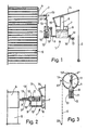
- the illustrated transmission system comprises a hydraulic or pneumatic circuit 1 which, actuated by a hand operated control (an operating rod 2), indirectly (see Figures 1 and 4) or directly (see Figures 2 and 3) causes a shaft 3 to rotate, said shaft carrying a drum 4 on which a blind 5 is wound up in the illustrated embodiment.
- the circuit 1 comprises a press formed by a cylinder 6 in which a press platen 7, when the rod 8 thereof is pushed, forces the fluid contained in said cylinder through a conduit 9 to the top portion of a cylinder 10, which is also full of fluid.
- the cylinder 10 is provided with a piston 11 which is urged from underneath by a spring 12 located in the lower portion of the cylinder 10. Under the pressure created by the platen, the piston 11 overcomes the opposition of the spring and moves downward, compressing the spring 12 and impressing a downward linear movement on the rod 13 thereof.
- the press platen 7 is actuated through a manual action on the operating rod 2 which, by being pivotably connected to a lever 14 which in turn is pivotably connected at the other end thereof to a support (not shown) and at the mid portion thereof to the rod 8 of the said press platen 7, causes the latter to descend.
- lever 14 may also be pivotably connected to an arm 15 ( Figures 1 and 2), which is pivotably connected in turn to the upper edge of the cylinder 6.
- the circuit 1 is also provided with a fluid inlet conduit 16 having a stop cock 17 at the lower portion of the cylinder 6, both this conduit and the conduit 9 comprising respective valves 18.
- these valves 18 prevent both a sharp fluid pressure against the stop cock 17 and the equally sharp return of the fluid from the cylinder 10 to cylinder 6 when the press action ceases.
- the blind is held partly or wholly lifted by appropriate mechanical or manual fixing means (not shown), such as an attachment on the wall or window frame where the operating rod 2 may be held.
- the transmission of the linear movement of the rod 13 to the shaft 3 and the conversion thereof into a rotary movement is effected by a cable 19 attached at one end thereof to said rod and at the other end to the shaft 3.
- Said cable 19 is wound around the shaft 3 in the unfolded position of the blind 5, and the latter winds around the drum 4 when the cable 19 is unwound as by being pulled by the rod 13 when the circuit 1 is actuated.
- the cable 19 is prevented from mounting on itself on the shaft 3 by a pusher means formed, for example, by a resilient strip 20 or like member which engages the cable in the portion extending from its point of departure from the shaft 3 to its attachment to the rod 13.
- This transmission of movement from the rod 13 to the shaft 3 may also be effected by means of a chain 21 ( Figure 4) which half wraps a circular toothed portion (or sprocket) 22 of the shaft 3, one of the ends of said chain being attached to the rod 13 and the other end to a spring 23 which, attached in turn to the cylinder 10, allows the chain 21 to be moved and, at the same time, keeps it in engagement with the sprocket 22, without any possibility of disengagement therefrom.
- a chain 21 Figure 4 which half wraps a circular toothed portion (or sprocket) 22 of the shaft 3, one of the ends of said chain being attached to the rod 13 and the other end to a spring 23 which, attached in turn to the cylinder 10, allows the chain 21 to be moved and, at the same time, keeps it in engagement with the sprocket 22, without any possibility of disengagement therefrom.
- the attachment of the chain 21 by means of the spring 23 could be replaced or complemented by means for guiding said chain, either by a tube 24 in which the part attached to the spring 23 would be attached, or by a cowling 25 arranged over the portion engaging the sprocket 22.
- the transmission may also be formed by a belt or any other pertinent member logically having the appropriate strength and coupling means to the shaft 3 to cause it to rotate.
- the said transmission means may also be dispensed with by providing a helical thread 13′ on the shaft 13 ( Figure 2) and engaging it directly linearly with the shaft 3 which, likewise, will be provided with a helical thread 3′, forming a worm transmission.
- a helically threaded longitudinal orifice may also be provided in the interior of the shaft which would act as a nut for the piston shaft.
- a further embodiment of this direct action is the perpendicular arrangement of both members ( Figure 3) acting as a rack and pinion system, with a toothed portion 13 ⁇ on the rod 13 meshing with a circular toothed portion 3 ⁇ of the shaft 3, causing the latter to rotate when the former moves linearly, and causing the drum 4 also to rotate, which drum in view of the larger diameter thereof relative to the shaft 3 will require the rod 13 to move over a short distance to wind up the whole blind.
- the circular toothed portion of the shaft 3 may be replaced by the arrangement thereon of a pinion or gear wheel.
- the circuits of all of them may be connected by the conduit 16 thereof with stop cock 17 to a general compressor (not shown), with the valves 18 being replaced by other hand operated double acting valves or by direct control solenoid valves (e.g. by pushbutton or key) or remote control valves.
- a limit device 26 may also be installed on the blind ( Figure 3) which, on rising, actuates a microswitch 27. This, in turn, will start a preset timer (not shown), which will act on the appropriate solenoid valves to lower the blind after a preset time.
- the circuit 1 forms a block which may be enclosed in a box which may be located in the compartment where the drum 4 will be mounted, arranging it alongside or inside the compartment, since its size so allows, it being different from the illustrated ones, which have been shown schematically so that they may be more comprehensible, and with a bevel gear being provided when the perpendicular transmissions have to be made longitudinally inside the drum 4.
- the circuit may be significantly simplified if a pipeline containing a fluid of adequate pressure to activate the piston 11 is available.
- a fluid of adequate pressure to activate the piston 11 may be, for instance, mains water and the conduit 16 will be connected to the mains.
- the conduit will be directly connected, in turn, by two branches 16′ and 16 ⁇ , to the upper and lower portions of the cylinder 10 to be able to move the piston 11 in one way or the other, there being provided at the joint between said branches and the conduit 16 a valve 28 with which the mains water may be directed to one or the other branch, the cylinder 10 being provided with discharges (not shown) for the excess water on each operation of piston 11.
- the object of the invention may be embodied, within the essence thereof, in other ways differing only in detail from the embodiment illustrated only as an example, and which will also fall under the protection requested.
- the transmission system for rotating shafts for winding up blinds, doors and the like may be embodied with the most appropriate means, components and accessories and the components may be replaced with other technically equivalent ones, since all is comprised within the scope of the following claims.
Landscapes
- Engineering & Computer Science (AREA)
- Structural Engineering (AREA)
- Architecture (AREA)
- Civil Engineering (AREA)
- Blinds (AREA)
Priority Applications (1)
| Application Number | Priority Date | Filing Date | Title |
|---|---|---|---|
| EP89500089A EP0417373A1 (fr) | 1989-09-15 | 1989-09-15 | Système de transmission pour la rotation d'arbres d'enroulement de volets roulants, de portes roulantes et similaires |
Applications Claiming Priority (1)
| Application Number | Priority Date | Filing Date | Title |
|---|---|---|---|
| EP89500089A EP0417373A1 (fr) | 1989-09-15 | 1989-09-15 | Système de transmission pour la rotation d'arbres d'enroulement de volets roulants, de portes roulantes et similaires |
Publications (1)
| Publication Number | Publication Date |
|---|---|
| EP0417373A1 true EP0417373A1 (fr) | 1991-03-20 |
Family
ID=8203085
Family Applications (1)
| Application Number | Title | Priority Date | Filing Date |
|---|---|---|---|
| EP89500089A Withdrawn EP0417373A1 (fr) | 1989-09-15 | 1989-09-15 | Système de transmission pour la rotation d'arbres d'enroulement de volets roulants, de portes roulantes et similaires |
Country Status (1)
| Country | Link |
|---|---|
| EP (1) | EP0417373A1 (fr) |
Cited By (4)
| Publication number | Priority date | Publication date | Assignee | Title |
|---|---|---|---|---|
| NL1016241C2 (nl) * | 2000-09-22 | 2002-03-25 | Holstein Michel Nicolaas C Van | Scherminstallatie. |
| WO2006123371A1 (fr) * | 2005-05-19 | 2006-11-23 | Gianus S.P.A. | Systeme d’automatisation pneumatique pour des ecrans mobiles |
| JP2014074313A (ja) * | 2012-10-05 | 2014-04-24 | Komatsu Denki Sangyo Kk | エアー式のシャッタ装置 |
| CN103848367A (zh) * | 2013-09-26 | 2014-06-11 | 北京市三一重机有限公司 | 卷扬钢丝绳防过放方法、装置及卷扬机 |
Citations (3)
| Publication number | Priority date | Publication date | Assignee | Title |
|---|---|---|---|---|
| US1781646A (en) * | 1929-05-09 | 1930-11-11 | Norman V Kreger | Rear-curtain-operating device |
| US1837129A (en) * | 1930-12-27 | 1931-12-15 | Jack B Maples | Power hoist curtain |
| FR1006934A (fr) * | 1949-12-15 | 1952-04-29 | Dispositif de compensation, pour rideau roulant, utilisant la pression d'un huide |
-
1989
- 1989-09-15 EP EP89500089A patent/EP0417373A1/fr not_active Withdrawn
Patent Citations (3)
| Publication number | Priority date | Publication date | Assignee | Title |
|---|---|---|---|---|
| US1781646A (en) * | 1929-05-09 | 1930-11-11 | Norman V Kreger | Rear-curtain-operating device |
| US1837129A (en) * | 1930-12-27 | 1931-12-15 | Jack B Maples | Power hoist curtain |
| FR1006934A (fr) * | 1949-12-15 | 1952-04-29 | Dispositif de compensation, pour rideau roulant, utilisant la pression d'un huide |
Cited By (7)
| Publication number | Priority date | Publication date | Assignee | Title |
|---|---|---|---|---|
| NL1016241C2 (nl) * | 2000-09-22 | 2002-03-25 | Holstein Michel Nicolaas C Van | Scherminstallatie. |
| WO2006123371A1 (fr) * | 2005-05-19 | 2006-11-23 | Gianus S.P.A. | Systeme d’automatisation pneumatique pour des ecrans mobiles |
| US7921898B2 (en) | 2005-05-19 | 2011-04-12 | Gianus S.P.A. | Pneumatic automation system for mobile screens |
| CN101180445B (zh) * | 2005-05-19 | 2011-10-26 | 吉安纳斯有限公司 | 用于移动幕的气动自动化系统 |
| JP2014074313A (ja) * | 2012-10-05 | 2014-04-24 | Komatsu Denki Sangyo Kk | エアー式のシャッタ装置 |
| CN103848367A (zh) * | 2013-09-26 | 2014-06-11 | 北京市三一重机有限公司 | 卷扬钢丝绳防过放方法、装置及卷扬机 |
| CN103848367B (zh) * | 2013-09-26 | 2016-05-11 | 北京市三一重机有限公司 | 卷扬钢丝绳防过放方法、装置及卷扬机 |
Similar Documents
| Publication | Publication Date | Title |
|---|---|---|
| US7537039B2 (en) | Window blind driven by a window lifter | |
| US6910516B2 (en) | Curtain blind take-up drive mechanism with non-slip effect | |
| US6983786B2 (en) | Height-adjustable car curtain | |
| US4440354A (en) | Automatic tension-adjusting mechanism for window regulators | |
| EP0222062B1 (fr) | Dispositif pour ouvrir et fermer une porte industrielle | |
| US4344252A (en) | Garage door operation control apparatus | |
| CA2421479C (fr) | Methode et mecanisme de commande de levage de store | |
| US4917167A (en) | Skylight window covering and control means therefor | |
| EP1435425B1 (fr) | Méthode et mécanisme de levage pour store vénitien | |
| US4599824A (en) | Device for automatically opening and closing hinged door | |
| US4428542A (en) | Wire-driving device for window regulator | |
| DE69605983T2 (de) | Motorisierter Rolladen | |
| GB1077705A (en) | Improvements in or relating to apparatus for raising and lowering blinds | |
| CA3037454A1 (fr) | Dispositifs et methodes d'assemblages de fenetre convertibles de manuels a motorises | |
| US4262373A (en) | Swimming pool cover assembly | |
| EP0247010B1 (fr) | Appareil pour enrouler et dérouler une pellicule souple de parois latérales dans des serres et pour d'autres usages | |
| EP3825509B1 (fr) | Store | |
| EP0127107B1 (fr) | Dispositif d'entraînement pour sangles de volet enroulable | |
| DE3012465C2 (fr) | ||
| DE60102961T2 (de) | Motorisierte Antriebsvorrichtung von beweglichen Einrichtungen wie Rollos od.dgl. und Methode zur Bedienung | |
| EP0852281A2 (fr) | Carte électronique pour le contrÔle d'un moteur électrique | |
| EP4047172A1 (fr) | Dispositif de commande de porte moustiquaire pour l'ouverture et la fermeture automatiques d'une porte moustiquaire | |
| WO1995011540A1 (fr) | Dispositif enfileur pour elements filiformes | |
| DE1763441C3 (de) | Elektromotorische Jalousie-Antrlebsvorrichtung | |
| DE19500331A1 (de) | Aufroller für ein langgestrecktes, flexibles Element, insbesondere für einen Schlauch |
Legal Events
| Date | Code | Title | Description |
|---|---|---|---|
| PUAI | Public reference made under article 153(3) epc to a published international application that has entered the european phase |
Free format text: ORIGINAL CODE: 0009012 |
|
| AK | Designated contracting states |
Kind code of ref document: A1 Designated state(s): AT BE CH DE FR GB GR IT LI LU NL SE |
|
| STAA | Information on the status of an ep patent application or granted ep patent |
Free format text: STATUS: THE APPLICATION IS DEEMED TO BE WITHDRAWN |
|
| 18D | Application deemed to be withdrawn |
Effective date: 19910923 |