EP0417422A2 - Procédé et dispositif pour commander les feux de freinage d'un véhicule - Google Patents
Procédé et dispositif pour commander les feux de freinage d'un véhicule Download PDFInfo
- Publication number
- EP0417422A2 EP0417422A2 EP90113394A EP90113394A EP0417422A2 EP 0417422 A2 EP0417422 A2 EP 0417422A2 EP 90113394 A EP90113394 A EP 90113394A EP 90113394 A EP90113394 A EP 90113394A EP 0417422 A2 EP0417422 A2 EP 0417422A2
- Authority
- EP
- European Patent Office
- Prior art keywords
- control
- brake
- regulating unit
- brake lights
- current
- Prior art date
- Legal status (The legal status is an assumption and is not a legal conclusion. Google has not performed a legal analysis and makes no representation as to the accuracy of the status listed.)
- Withdrawn
Links
- 238000000034 method Methods 0.000 title claims abstract description 26
- 230000008569 process Effects 0.000 title claims abstract description 13
- 230000001105 regulatory effect Effects 0.000 claims abstract description 60
- 238000012544 monitoring process Methods 0.000 claims abstract description 15
- 230000001276 controlling effect Effects 0.000 claims abstract description 5
- 238000011156 evaluation Methods 0.000 claims description 3
- 230000004044 response Effects 0.000 claims description 3
- 230000007257 malfunction Effects 0.000 description 3
- 239000013307 optical fiber Substances 0.000 description 3
- 230000002950 deficient Effects 0.000 description 2
- 230000000007 visual effect Effects 0.000 description 2
- 230000009471 action Effects 0.000 description 1
- 230000015556 catabolic process Effects 0.000 description 1
- 230000001934 delay Effects 0.000 description 1
- 230000001419 dependent effect Effects 0.000 description 1
- 238000001514 detection method Methods 0.000 description 1
- 238000010586 diagram Methods 0.000 description 1
- 230000010365 information processing Effects 0.000 description 1
- 230000005693 optoelectronics Effects 0.000 description 1
- 230000003647 oxidation Effects 0.000 description 1
- 238000007254 oxidation reaction Methods 0.000 description 1
- 230000000737 periodic effect Effects 0.000 description 1
- 230000009467 reduction Effects 0.000 description 1
- 230000000717 retained effect Effects 0.000 description 1
- 238000004148 unit process Methods 0.000 description 1
Images
Classifications
-
- B—PERFORMING OPERATIONS; TRANSPORTING
- B60—VEHICLES IN GENERAL
- B60Q—ARRANGEMENT OF SIGNALLING OR LIGHTING DEVICES, THE MOUNTING OR SUPPORTING THEREOF OR CIRCUITS THEREFOR, FOR VEHICLES IN GENERAL
- B60Q1/00—Arrangement of optical signalling or lighting devices, the mounting or supporting thereof or circuits therefor
- B60Q1/26—Arrangement of optical signalling or lighting devices, the mounting or supporting thereof or circuits therefor the devices being primarily intended to indicate the vehicle, or parts thereof, or to give signals, to other traffic
- B60Q1/44—Arrangement of optical signalling or lighting devices, the mounting or supporting thereof or circuits therefor the devices being primarily intended to indicate the vehicle, or parts thereof, or to give signals, to other traffic for indicating braking action or preparation for braking, e.g. by detection of the foot approaching the brake pedal
- B60Q1/448—Arrangement of optical signalling or lighting devices, the mounting or supporting thereof or circuits therefor the devices being primarily intended to indicate the vehicle, or parts thereof, or to give signals, to other traffic for indicating braking action or preparation for braking, e.g. by detection of the foot approaching the brake pedal specially adapted for vehicles with ABS
-
- B—PERFORMING OPERATIONS; TRANSPORTING
- B60—VEHICLES IN GENERAL
- B60Q—ARRANGEMENT OF SIGNALLING OR LIGHTING DEVICES, THE MOUNTING OR SUPPORTING THEREOF OR CIRCUITS THEREFOR, FOR VEHICLES IN GENERAL
- B60Q11/00—Arrangement of monitoring devices for devices provided for in groups B60Q1/00 - B60Q9/00
Definitions
- the invention relates to a method and an arrangement for controlling and monitoring the brake lights of a vehicle, wherein a brake light switch arranged in a master brake cylinder is closed when the brake system is actuated.
- the brake lights of vehicles are intended to alert the drivers of following motor vehicles to the decrease in speed when braking, so that collisions can be avoided by braking the following vehicles in good time. If the brake lights malfunction, there is a great danger to the following vehicles, in particular when there are small distances between two vehicles at higher speeds. It is therefore desirable that the vehicle occupants can detect breakdowns of the brake lights while driving, in order to avoid collisions with other vehicles as quickly as possible by immediately eliminating a malfunction or behavior that does not or only slightly endangers other road users.
- the invention is therefore based on the object of further developing a method and an arrangement for controlling the brake lights of a vehicle in such a way that failure of the display by the brake lights can be determined quickly with as little effort as possible.
- a control and regulating unit in the vehicle which is supplied with a signal for evaluation by at least one wheel speed sensor, the signal present at the brake light switch is additionally supplied, that when the brake light switch is actuated and / or when it is detected a braking process from the signal of the wheel speed sensor, a current for brake light generation from the control and regulating unit is fed into the brake lights, that the operability of the brake lights is monitored by the control and regulating unit and that with the brake light switch open during braking and / or in the event of inoperability the brake lights produce an error message.
- the control and Control unit in the vehicle used.
- Control units already present in the vehicle can also be used to control and monitor the brake lights if they evaluate at least one wheel speed signal.
- the control and regulating unit is preferably part of an anti-lock system.
- Anti-lock braking systems are already present in numerous motor vehicles and can be used for the control and monitoring of the brake lights in addition to their function as an anti-lock braking system.
- Anti-slip controllers can also take over the brake light control and monitoring. It is also possible to set on-board computers that are also connected to the brake light switch and brake lights to control and monitor the brake lights.
- Brake systems with anti-lock controls are known and are used in numerous vehicles.
- Such braking systems contain z.
- B. a master brake cylinder with a pedal-operated brake light switch and an electronic control unit that receives the signals from wheel speed sensors and generates the electrical brake pressure control signals for slip regulators in pressure medium lines of the wheel brakes.
- the braking systems therefore consist of a hydraulic-mechanical system, the electronic control and regulating unit and electromagnetically controlled components that act on the pressure in the wheel brakes.
- the control and regulating unit processes signals from the wheel speed sensors in order to determine the wheel speeds. Numerical values corresponding to the vehicle speed and the brake slip are determined from this. Based on these numerical values, the control and regulating unit takes one suitable pressure modulation in the wheel brakes.
- the regulating and control unit is redundant, e.g. B. built from at least two processors.
- the two e.g. Processors with the same structure, for example, receive the same input signals and monitor each other.
- a fault e.g. B. a component error in the other processor, switch off the slip control. Then the normal braking function is retained. A fault is displayed in the vehicle.
- the control and regulating unit performs the monitoring of the brake light circuits and the control of the brake lights in addition to the brake slip control. Due to the high operating speed of the control and regulating unit, this task can also be performed.
- the brake lights are also supplied directly with the brake light switch when braking with current for the display of the braking process. This ensures that a complete failure of the control and regulating unit does not prevent the brake lights from being supplied with current. This significantly increases the safety of the visual display of a braking process.
- the current flowing through the brake lights is changed by an increase and / or by periodic reduction or interruption compared to the current flowing when braking without slip control.
- the visual displays differ when braking with and without slip control. Because of this difference, the drivers of vehicles behind can adjust their driving behavior to the ABS braking process of the vehicle in front.
- the braking deceleration is monitored for a threshold which is above the maximum deceleration values which occur during the slip control, the brake lights being continuously supplied with power by the control and regulating unit after this threshold has been exceeded. Deceleration values above the deceleration values of the slip control generally occur in rear-end collisions. In such a case, with the measures described above, the brake lights are supplied with power even when the vehicle is at a standstill, ie even after the rear-end collision. If the brake lights, the control and regulating unit and the battery have survived the accident properly, the brake lights remain in operation so that other drivers are warned faster. In particular, the brake lights are supplied with a pulsating current after a rear-end collision in order to generate a pulsating display as in the operation of the hazard warning lights.
- the control and regulating unit is preferably supplied with current when the ignition voltage is switched on.
- the control and regulating unit therefore always monitors the brake light switch and the brake lights during operation of the vehicle. Even after an accident, the anti-lock braking system remains in operation and supplies the brake lights with power when they are intact.
- An arrangement for performing the method described above is that a normally open contact of a brake light switch is arranged between one pole of the battery and an input of a control and regulating unit, that the brake light is connected in parallel between an output of the control and regulating unit and the other pole of the Battery are arranged and that at least one sensor detecting the response of the brake lights is connected to a further input of the control and regulating unit.
- an already existing control and regulating unit is used for the monitoring and actuation of the brake lights, which, in addition to any slip control that may be required, can take over the control and monitoring function of the brake lights due to its high working speed.
- the control and regulation unit works independently of the monitoring of the brake light switch and the brake lights, as well as the control of the brake lights.
- a current path is preferably arranged parallel to the control and regulating unit between the brake light switch and the brake lights. This arrangement makes a parallel branch created for the brake lights, which are therefore supplied with power even if the control unit fails when the brake light switch is actuated.
- the control and regulating unit is implemented in particular by the electronics of an anti-lock system, an anti-slip control arrangement or an on-board computer.
- the invention is based on a. described in more detail in a drawing, from which further details, features and advantages result.
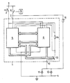
- the drawing shows a control and regulating unit of an anti-lock braking system in connection with a brake light switch and with brake lights in the block diagram.
- the control and regulating unit (1) can belong to an anti-lock system.
- the control and regulating unit (1) is connected with its operating voltage connection to a pole (3) of a battery in the motor vehicle via a switch (2) which is closed when the ignition of a motor vehicle is switched on.
- the other operating voltage connection of the control and regulating unit (1) is connected to the second pole (4) of the battery, which is connected to ground.
- the control and regulating unit (1) contains two processors (5, 6) for function monitoring of the anti-lock system. Redundancy is achieved in this way.
- the brake lights can also be controlled and monitored using an anti-lock braking system that contains only one processor.
- the two processors (5, 6) receive the same input signals and are in theirs Program structure the same.
- the signal streams of the processors (5, 6) are compared several times with one another via channels that are not specified.
- a signal path is intended for the synchronization of the processors (5, 6) and enables mutual monitoring of the clock frequencies.
- Each processor can switch off or temporarily stop the anti-lock system via one output independently of the other. Errors, e.g. B. component errors in the processors (5, 6) are recognized by the redundant information processing in both processors, which leads to a shutdown of the anti-lock system and to the generation of an error message.
- a make contact (8) of a brake light switch (9) which is located in the master brake cylinder.
- the input (7) is connected to both processors (5, 6).
- a connection (10) of the control and regulating unit (i) two brake lights (11, 12) are connected in parallel, which are connected to ground with their second connections.
- the connection (10) is preceded by a contactless switching element (13) controlled by the processors (5, 6), which is connected to the switch (2) via a current sensor (14), a resistor.
- a current path with a resistor (15) branches off from the input (7), the size of which corresponds to the resistance of the current sensor (14).
- the current sensor is connected to an input of the processors (5, 6).
- the current path with the resistor (15) is connected to the brake lights (11, 12).
- the control and regulating unit (1) is supplied with operating voltage when the switch (2) is closed and begins to work.
- the signal at the input (7) is checked by the control unit to determine whether the normally open contact (8) is closed or not. A closed make contact (8) and thus an actuated brake light switch (9) cause a high signal level at the input (7). If there is a high signal level at the input (7), the control and regulating unit (1) closes the switching element (13), as a result of which the brake lights (11, 12) are supplied with current and light up.
- the control and regulating unit (i) checks whether there is a high level at the input (7) on the current sensor (14) which indicates a current flow, ie the power supply to the brake lights (i1, 12) and thus their correct functioning is recognized by the detection of a current flow in the current sensor (14).
- the amount of current flow via the voltage drop at the current sensor can also be evaluated as a sign of undisturbed operation of both or only one brake light.
- the resistance of the current sensor (14) and the resistor (15) are matched to one another so that after the make contact (8) is closed, part of the current of the brake lights (11, 12) via the current sensor (14) and part via the resistor (15) flows. If the control and regulating unit (1) fails, the brake lights (11, 12) are supplied with current via the parallel current path with the resistor (15).
- the control and regulating unit (1) If a failure of the brake light (11, 12) is detected by the control and regulating unit when the brake light switch (9) is actuated, the control and regulating unit (1) generates an error message. The defective brake light can then be replaced immediately.
- the control and regulation unit (1) monitors a braking process by a plausibility check using the wheel speeds that are available in the control and regulation unit (1). The control and regulating unit (1) determines the presence of vehicle braking from the changes in the wheel speeds in comparison with predetermined deceleration values that correspond to braking processes. The switching element (13) is then closed regardless of whether the brake light switch (9) is closed or not, which makes the brake lights (11, 12) light up.
- the presence of a slip control which is carried out by the control and regulating unit (1), causes the switching element (13) to close. If the control and regulating unit (1) detects a braking operation without the brake light switch (9) being actuated, an error message is also generated.
- the control and regulating unit (1) determines the difference between braking with and without slip control.
- the control and regulating unit reacts to the two different braking processes by controlling the brake lights (11, 12) differently.
- the control and regulating unit (1) opens and closes the switching element (13) z. B. periodically with a slip control, so that the brake lights periodically show fluctuations in brightness. These fluctuations in brightness make other road users aware that heavy braking is taking place. It is also possible e.g. B. by feeding a higher current by switching to a higher voltage source to increase the brightness of the brake lights (11, 12) with a slip control.
- the control and regulating unit (1) also compares the calculated braking decelerations with a predetermined value which is above the braking decelerations possible with slip control. For example, this comparison value is greater than the many delays that occur in the case of a dry road surface and high tire pressure.
- the comparison value can e.g. B. be higher by a factor of 2 than this maximum braking deceleration.
- the occurrence of such a high braking deceleration is the sign of an accident.
- the control and regulating unit (1) reacts to the occurrence of such a braking deceleration by supplying the brake lights (11, 12) with current even when the vehicle is at a standstill. If, after the accident, the control and regulating unit and the brake lights (11, 12) can be operated properly, the brake lights (11, 12) light up to warn other road users.
- the response of the brake lights can also be photoelectrically reported to the control and regulating unit by adding a photoelectric receiver, e.g. B. a phototransistor, arranged on a brake light and connected to at least one input of the control unit.
- a photoelectric receiver e.g. B. a phototransistor
- optical fibers are provided on the brake lights (11, 12).
- the other ends of the optical fibers are arranged on photoelectric receivers which are connected to inputs of the control and regulating unit.
- the anti-lock braking system (1) described above is only given as an example of an electronic control that evaluates at least one wheel speed signal from a wheel speed sensor. The evaluation relates to whether braking is taking place or not. If such an arrangement has the ability to detect braking processes, then it can be converted or adjusted by the supply of a signal which is dependent on the position of the brake light switch and by an action on the brake lights so that they perform the control and monitoring functions for the brake lights described above additionally executes.
- Electronic circuits that can be used for the control and monitoring of brake lights are, in particular, anti-slip controllers and on-board computers.
- the brake lights (11, 12) can also be monitored as a precautionary measure if the vehicle is not braking. For this purpose, such a small current is fed into the brake lights (11, 12) that there is no lighting up, but a current flow is clearly recognized at the current sensor (14). If no current flow is detected, this is a criterion that the brake light is not functional. This can have different causes. For example, the particular bulb may be defective. A line break or oxidation of contacts is also possible. A non-functional brake light causes an immediate message so that the fault can be identified immediately and, if necessary, rectified immediately.
- the functionality of the brake lights is therefore monitored either when braking or even when there is no braking.
- the functionality of the brake lights can be detected, in particular by detecting the lamp current or by optical fibers with optoelectronic elements which detect the light emitted.
Landscapes
- Engineering & Computer Science (AREA)
- Mechanical Engineering (AREA)
- Lighting Device Outwards From Vehicle And Optical Signal (AREA)
Applications Claiming Priority (2)
| Application Number | Priority Date | Filing Date | Title |
|---|---|---|---|
| DE19893930775 DE3930775A1 (de) | 1989-09-14 | 1989-09-14 | Verfahren und anordnung zur steuerung der bremsleuchten eines fahrzeugs |
| DE3930775 | 1989-09-14 |
Publications (2)
| Publication Number | Publication Date |
|---|---|
| EP0417422A2 true EP0417422A2 (fr) | 1991-03-20 |
| EP0417422A3 EP0417422A3 (en) | 1991-09-18 |
Family
ID=6389466
Family Applications (1)
| Application Number | Title | Priority Date | Filing Date |
|---|---|---|---|
| EP19900113394 Withdrawn EP0417422A3 (en) | 1989-09-14 | 1990-07-13 | Process and device for controlling the brake lights of a vehicle |
Country Status (2)
| Country | Link |
|---|---|
| EP (1) | EP0417422A3 (fr) |
| DE (1) | DE3930775A1 (fr) |
Cited By (3)
| Publication number | Priority date | Publication date | Assignee | Title |
|---|---|---|---|---|
| EP1167121A3 (fr) * | 2000-06-23 | 2006-04-12 | Reitter & Schefenacker GmbH & Co. KG | Dispositif de surveillance d'une commande en particulier pour les feux d'un véhicule |
| DE102014212628A1 (de) * | 2014-06-30 | 2015-12-31 | Phoenix Contact Gmbh & Co. Kg | Sammelfernmeldevorrichtung |
| CN112874432A (zh) * | 2021-02-08 | 2021-06-01 | 一汽解放汽车有限公司 | 一种制动灯控制系统、方法和驾驶设备 |
Families Citing this family (8)
| Publication number | Priority date | Publication date | Assignee | Title |
|---|---|---|---|---|
| DE4243693A1 (de) * | 1992-12-18 | 1994-06-23 | Reinhold Mettig | Rückwärtige Signalvorrichtung für ein Straßenfahrzeug |
| DE19504411B4 (de) * | 1995-02-10 | 2007-06-06 | Knorr-Bremse Systeme für Nutzfahrzeuge GmbH | Verfahren und Vorrichtung zur Anzeige eines Bremsvorgangs bzw. einer Bremspedalbetätigung |
| DE19610871C1 (de) * | 1996-03-20 | 1997-06-19 | Daimler Benz Ag | Steuerungsvorrichtung, insbesondere zur Fahrzeugbremslichtsteuerung |
| DE19814482A1 (de) * | 1998-04-01 | 1999-10-07 | Bosch Gmbh Robert | Verfahren und Vorrichtung zur Erzeugung eines Fehlersignals bei einem Kraftfahrzeug |
| DE10116276B4 (de) * | 2001-03-31 | 2019-07-04 | Volkswagen Ag | Fahrzeug mit Verzögerungswarnlicht |
| DE10158224B4 (de) * | 2001-11-16 | 2005-02-10 | Andreas Godyn | Mobiles optoelektronisches Testgerät für Kfz-Bremslichter, insbesondere an diversen Anhängerarten |
| DE102005062020A1 (de) * | 2005-12-22 | 2007-01-25 | Daimlerchrysler Ag | Vorrichtung zur Information bei Leuchtenausfall an Fahrzeugen |
| DE102016200833B4 (de) * | 2016-01-21 | 2025-07-17 | Volkswagen Aktiengesellschaft | Vorrichtung zur Ansteuerung von Bremslichtern eines Kraftfahrzeugs mit redundanten Signalleitungen, Kraftfahrzeug sowie Verfahren |
Family Cites Families (6)
| Publication number | Priority date | Publication date | Assignee | Title |
|---|---|---|---|---|
| DE3233765A1 (de) * | 1982-09-11 | 1984-03-15 | Vdo Adolf Schindling Ag, 6000 Frankfurt | Ansteuereinrichtung |
| US4594574A (en) * | 1984-11-05 | 1986-06-10 | Thurman John S | Vehicle motion signalling system |
| JPS61261145A (ja) * | 1985-05-15 | 1986-11-19 | Toyota Motor Corp | 車両用故障診断装置 |
| DE3614977A1 (de) * | 1986-05-02 | 1987-11-05 | Peter Hamann | Bremslichtsteuervorrichtung und verfahren zur bremslichtsteuerung |
| DE3737688A1 (de) * | 1987-11-06 | 1989-05-18 | Bosch Gmbh Robert | Anordnung zur ueberwachung der funktion des bremslichtschalters eines fahrzeugs |
| JP2717251B2 (ja) * | 1988-02-09 | 1998-02-18 | マツダ株式会社 | アンチロック装置 |
-
1989
- 1989-09-14 DE DE19893930775 patent/DE3930775A1/de not_active Withdrawn
-
1990
- 1990-07-13 EP EP19900113394 patent/EP0417422A3/de not_active Withdrawn
Cited By (6)
| Publication number | Priority date | Publication date | Assignee | Title |
|---|---|---|---|---|
| EP1167121A3 (fr) * | 2000-06-23 | 2006-04-12 | Reitter & Schefenacker GmbH & Co. KG | Dispositif de surveillance d'une commande en particulier pour les feux d'un véhicule |
| DE102014212628A1 (de) * | 2014-06-30 | 2015-12-31 | Phoenix Contact Gmbh & Co. Kg | Sammelfernmeldevorrichtung |
| DE102014212628B4 (de) * | 2014-06-30 | 2016-04-14 | Phoenix Contact Gmbh & Co. Kg | Sammelfernmeldevorrichtung |
| US9825697B2 (en) | 2014-06-30 | 2017-11-21 | Phoenix Contact Gmbh & Co. Kg | Collective remote signaling device |
| CN112874432A (zh) * | 2021-02-08 | 2021-06-01 | 一汽解放汽车有限公司 | 一种制动灯控制系统、方法和驾驶设备 |
| CN112874432B (zh) * | 2021-02-08 | 2023-03-24 | 一汽解放汽车有限公司 | 一种制动灯控制系统、方法和驾驶设备 |
Also Published As
| Publication number | Publication date |
|---|---|
| DE3930775A1 (de) | 1991-03-28 |
| EP0417422A3 (en) | 1991-09-18 |
Similar Documents
| Publication | Publication Date | Title |
|---|---|---|
| EP0757638B1 (fr) | Circuiterie pour systemes de freinage a repartition electronique de la force de freinage | |
| DE102005006867B4 (de) | Halbleiterschalter mit Spannungsüberwachung | |
| EP0728086B1 (fr) | Systeme de freinage electronique | |
| EP1032517B1 (fr) | Systeme de freinage electromecanique | |
| DE3418042C2 (fr) | ||
| EP0415039B1 (fr) | Circuit électronique pour surveiller un amplificateur de sortie et sa charge | |
| DE19511388C1 (de) | Sicherheitsvorrichtung für ein Kraftfahrzeug | |
| EP0503225A2 (fr) | Installation avec des moyens pour reconnaître des défauts et affichage | |
| DE19840944B4 (de) | Sicherheitsrelevantes System, insbesondere elektromechanisches Bremssystem | |
| EP3833585B1 (fr) | Système de frein pour véhicule | |
| DE4334260A1 (de) | Steuervorrichtung für ein Fahrzeug mit einem Antiblockier-Bremssystem und einem Servolenkungs-Steuersystem | |
| DE2209745B2 (de) | Bremsblockierschutz-Steueranlage | |
| DE19607429B4 (de) | Fehlertolerante Steuerungseinrichtung für ein physikalisches System, insbesondere Fahrdynamikregeleinrichtung für ein Kraftfahrzeug | |
| EP1966016B1 (fr) | Bouton d'actionnement d'un frein a main electropneumatique (eph) | |
| EP0417422A2 (fr) | Procédé et dispositif pour commander les feux de freinage d'un véhicule | |
| WO1998035864A1 (fr) | Procede et dispositif permettant de commander la repartition de la force de freinage d'un vehicule automobile | |
| DE102021112049A1 (de) | Fahrzeugbremssystem und verfahren zur bedienung desselben | |
| DE102017118174A1 (de) | Brake-by-wire-system | |
| DE3627588A1 (de) | Vorrichtung zum erfassen von fehlfunktionen eines sensors | |
| EP2628147B1 (fr) | Dispositif et procédé de signalisation de dysfonctionnements dans un véhicule | |
| EP4405219B1 (fr) | Procédé de réalisation automatique d'un processus de freinage pour un véhicule en cas de défaillance d'une alimentation en tension du véhicule, et système de sécurité électronique de véhicule et véhicule | |
| DE102021210000A1 (de) | Verfahren zum Beurteilen eines Beschleunigungsvorgangs eines Fahrzeugs, sowie Beschleunigungssystem und Fahrzeug | |
| EP0494168B1 (fr) | Systeme de regulation de pression de freinage | |
| DE19907338A1 (de) | Bremssystem und Verfahren zu seiner Steuerung | |
| DE102021202060A1 (de) | Verfahren zum Betreiben einer Bremsvorrichtung |
Legal Events
| Date | Code | Title | Description |
|---|---|---|---|
| PUAI | Public reference made under article 153(3) epc to a published international application that has entered the european phase |
Free format text: ORIGINAL CODE: 0009012 |
|
| AK | Designated contracting states |
Kind code of ref document: A2 Designated state(s): DE FR GB IT SE |
|
| PUAL | Search report despatched |
Free format text: ORIGINAL CODE: 0009013 |
|
| AK | Designated contracting states |
Kind code of ref document: A3 Designated state(s): DE FR GB IT SE |
|
| 17P | Request for examination filed |
Effective date: 19910807 |
|
| 17Q | First examination report despatched |
Effective date: 19930422 |
|
| RAP1 | Party data changed (applicant data changed or rights of an application transferred) |
Owner name: FAHRZEUGTECHNIK EBERN GMBH |
|
| STAA | Information on the status of an ep patent application or granted ep patent |
Free format text: STATUS: THE APPLICATION IS DEEMED TO BE WITHDRAWN |
|
| 18D | Application deemed to be withdrawn |
Effective date: 19940903 |