EP0417480A2 - Système de câblage pour véhicules - Google Patents
Système de câblage pour véhicules Download PDFInfo
- Publication number
- EP0417480A2 EP0417480A2 EP90115354A EP90115354A EP0417480A2 EP 0417480 A2 EP0417480 A2 EP 0417480A2 EP 90115354 A EP90115354 A EP 90115354A EP 90115354 A EP90115354 A EP 90115354A EP 0417480 A2 EP0417480 A2 EP 0417480A2
- Authority
- EP
- European Patent Office
- Prior art keywords
- lines
- functions
- control
- cable set
- cabling system
- Prior art date
- Legal status (The legal status is an assumption and is not a legal conclusion. Google has not performed a legal analysis and makes no representation as to the accuracy of the status listed.)
- Granted
Links
- 238000012546 transfer Methods 0.000 claims abstract description 14
- 230000005540 biological transmission Effects 0.000 claims abstract description 7
- 230000000712 assembly Effects 0.000 claims abstract 2
- 238000000429 assembly Methods 0.000 claims abstract 2
- 230000003287 optical effect Effects 0.000 claims 1
- 238000000926 separation method Methods 0.000 description 6
- 238000011161 development Methods 0.000 description 3
- 230000018109 developmental process Effects 0.000 description 3
- 238000004519 manufacturing process Methods 0.000 description 2
- 238000007796 conventional method Methods 0.000 description 1
- 238000013461 design Methods 0.000 description 1
- 238000010586 diagram Methods 0.000 description 1
- 238000000034 method Methods 0.000 description 1
- 230000002093 peripheral effect Effects 0.000 description 1
- 230000000717 retained effect Effects 0.000 description 1
- 239000004065 semiconductor Substances 0.000 description 1
- 230000001960 triggered effect Effects 0.000 description 1
Images




Classifications
-
- H—ELECTRICITY
- H02—GENERATION; CONVERSION OR DISTRIBUTION OF ELECTRIC POWER
- H02G—INSTALLATION OF ELECTRIC CABLES OR LINES, OR OF COMBINED OPTICAL AND ELECTRIC CABLES OR LINES
- H02G3/00—Installations of electric cables or lines or protective tubing therefor in or on buildings, equivalent structures or vehicles
-
- H—ELECTRICITY
- H01—ELECTRIC ELEMENTS
- H01H—ELECTRIC SWITCHES; RELAYS; SELECTORS; EMERGENCY PROTECTIVE DEVICES
- H01H2300/00—Orthogonal indexing scheme relating to electric switches, relays, selectors or emergency protective devices covered by H01H
- H01H2300/03—Application domotique, e.g. for house automation, bus connected switches, sensors, loads or intelligent wiring
Definitions
- the invention relates to a cabling system according to the preamble of claim 1.
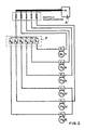
- the wiring in motor vehicles is known, in which actuators are switched via switches located in the console P.
- the power supply is switched directly (Fig.1).
- a further development is as follows: The power lines are separated from the control lines (see Fig. 2). This means that one power line is laid for each actuator M or, if necessary, all are connected to a common power rail. This is only a question of protection, which is not considered here.
- control lines are now drawn to each actuator, which are operated using switches S located in the console P.
- a corresponding electrical switch, a relay or a semiconductor switch E1 switches the load line on the actuator M1.
- the method is retained, but the control information is no longer transmitted to the switches E at the actuators M via a single supply line, but is transmitted in serial form on a common connecting line, the bus line, to all of them BUS modules B are connected.
- the bus modules have the task of encoding and decoding the large number of control signals to be transmitted for serial transmission in one signal path.
- the number of load lines remains the same; only a single line is required for data transmission (Fig. 3).
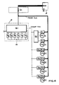
- FIG. 4 shows an electronic bus system with programmable bus modules B, fuses Si and circuit breakers E. There is a common power supply line, a so-called power supply bus.
- the electronic switches E1, which are located on the actuators M1, are connected to this bus. These electronic switches are designed so that they contain electronic fuses and thus central protection of individual lines is no longer necessary.
- the electronic switches E and the operating switches S in the console P are each connected to BUS modules B, which all communicate with one another via the control BUS.
- Fig. 4 shows that the electronic switches E1 and E2 of the actuators M1 and M2 are controlled, for example, by the common bus module B2, while the electronic switches E3 ... E6 each have their own bus modules B3 ... B6.
- Fig. 4 is only the transmission of control signals from Console P to the actuators M shown. It is customary to design the BUS modules B in such a way that signals can be transmitted in both directions via only one control BUS.
- the invention is based on the object of specifying a cable set which can be used for all equipment variants and also without a bus system.
- FIG. 5 An example of the wiring in a motor vehicle is shown in FIG. 5. Consumers M or modules B are connected via a cable harness 1 via connectors ST.
- the control panel P is arranged centrally in front of the driver. In most cases, the body K serves as a return line for the individual circuits, which are assigned to the special functions that are to be triggered by switches.
- a bus system is used (for multi-functions), which can switch a large number of functions (up to over 50 or 100), if more convenient, via the ten lines with a tens plug connection, for example, which are present in a basic configuration without a bus system Vehicle equipment should have more functions.
- Possibility A for example, allows a sufficient number to be transmitted with direct switches and load lines
- variant B by using additional modules at the ends of the cable set, to implement any desired, even programmable, multiple use of this cable set. For example, there are up to 100 functions.
- the invention makes it possible to realize this multiple use of the cable set for every conceivable additional function with minimal additional effort.
- An essential idea of the invention is that a fixed cable set up to the defined transfer point, e.g. to the console P or to the battery.
- cables are connected to these transfer points or separation points ST, which lead directly to the corresponding actuators and sensors.
- a module is connected to the transfer point, which in turn can connect a larger number of actuators and sensors on the output side.
- the power lines leading to the actuators supplied by this transfer point become an energy track for everyone - i.e. also summarized the additional actuators.
- the power lines that are routed within the fixed cable set are designed so strongly that the maximum energy that is conceivable at the end points can be transmitted.
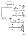
- the sensors and actuators are connected directly; For example, it is possible to connect more than 50 actuators and sensors M1 ... M50, S7 ... S18.
- the control panel P is also connected to the five lines via a detachable connection on the other side of the cable set.
- the line pairs provided as bus lines are connected to one another in the usual way, so that information can be exchanged between the peripheral modules and the modules in the console P at all the intended locations on the vehicle.
- FIG. 7 shows only five lines, two of which are used as bus lines and the three other lines are used as supply lines, but more than five lines can also be present.
- two lines 3 'and 3 ⁇ were connected to each other on the one hand, and lines 13, 13' and 13 ⁇ on the other side to connector ST4. These supply lines form an energy track.
- the line 3 goes directly to an actuator (here M50), while the other two lines 3 'and 3' are combined to form an energy rail.
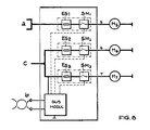
- Battery A which is connected to ground on one side, is used for power supply.
- the fuse and switch modules SM1, SM2 and SM3 each contain an electronic fuse (ES1, ES2, and ES3) and electrical switches S1 to S3.
- the bus module controls the electrical switches and connects the actuators M to the supply voltage, which is supplied via the energy rail a or c.
Landscapes
- Architecture (AREA)
- Civil Engineering (AREA)
- Structural Engineering (AREA)
- Engineering & Computer Science (AREA)
- Forklifts And Lifting Vehicles (AREA)
- Installation Of Indoor Wiring (AREA)
- Selective Calling Equipment (AREA)
- Windings For Motors And Generators (AREA)
- Motor Or Generator Cooling System (AREA)
- Small-Scale Networks (AREA)
- Train Traffic Observation, Control, And Security (AREA)
- Steering-Linkage Mechanisms And Four-Wheel Steering (AREA)
- Details Of Indoor Wiring (AREA)
- Insulated Conductors (AREA)
- Transplanting Machines (AREA)
- Sowing (AREA)
- Non-Portable Lighting Devices Or Systems Thereof (AREA)
Applications Claiming Priority (2)
| Application Number | Priority Date | Filing Date | Title |
|---|---|---|---|
| DE3930153 | 1989-09-09 | ||
| DE3930153A DE3930153A1 (de) | 1989-09-09 | 1989-09-09 | Verkabelungssystem fuer fahrzeuge |
Publications (3)
| Publication Number | Publication Date |
|---|---|
| EP0417480A2 true EP0417480A2 (fr) | 1991-03-20 |
| EP0417480A3 EP0417480A3 (en) | 1992-11-25 |
| EP0417480B1 EP0417480B1 (fr) | 1995-01-18 |
Family
ID=6389085
Family Applications (1)
| Application Number | Title | Priority Date | Filing Date |
|---|---|---|---|
| EP90115354A Expired - Lifetime EP0417480B1 (fr) | 1989-09-09 | 1990-08-10 | Système de câblage pour véhicules |
Country Status (7)
| Country | Link |
|---|---|
| EP (1) | EP0417480B1 (fr) |
| AT (1) | ATE117468T1 (fr) |
| DD (1) | DD297737A5 (fr) |
| DE (2) | DE3930153A1 (fr) |
| DK (1) | DK0417480T3 (fr) |
| ES (1) | ES2069640T3 (fr) |
| HU (1) | HU206657B (fr) |
Cited By (4)
| Publication number | Priority date | Publication date | Assignee | Title |
|---|---|---|---|---|
| EP0714812A3 (fr) * | 1991-03-28 | 1996-07-17 | Yazaki Corp | |
| EP0945308A3 (fr) * | 1998-03-26 | 2002-06-05 | Grote & Hartmann GmbH & Co. KG | Arrangement de circuit pour une centrale électrique de voiture |
| US8142235B2 (en) | 2006-03-03 | 2012-03-27 | Auto Kabel Managementgesellschaft Mbh | Arrangement for current distribution and contact arrangement and fuse protection thereof of the outgoing cables |
| FR3088872A1 (fr) * | 2018-11-27 | 2020-05-29 | Renault S.A.S. | Réseau d’alimentation électrique embarqué dans un véhicule. |
Families Citing this family (13)
| Publication number | Priority date | Publication date | Assignee | Title |
|---|---|---|---|---|
| DE4426338A1 (de) * | 1994-07-25 | 1995-09-28 | Daimler Benz Ag | Einrichtung zum Anschluß einer Vielzahl von elektrischen Verbrauchern und/oder Befehlsgebern in einer Kfz-Türe |
| DE4441268A1 (de) * | 1994-11-19 | 1996-05-23 | Daimler Benz Ag | Mehrfachleitung für Gleich- und Wechselspannungen |
| DE19511755C1 (de) * | 1995-03-30 | 1996-08-22 | Framatome Connectors Int | Multiplex-Steuerung von Komponenten bzw. Untersystemen in Kraftfahrzeugen |
| DE19526806A1 (de) * | 1995-07-13 | 1997-01-16 | Siemens Ag | Bordnetz mit Multiplexsteuerung für Kraftfahrzeuge |
| DE19701878A1 (de) * | 1997-01-21 | 1998-06-25 | Bosch Gmbh Robert | Vorrichtung zum Ansteuern von Hochstromverbrauchern |
| DE19703236A1 (de) * | 1997-01-29 | 1998-07-30 | Siemens Ag | Schalteranordnung für elektrische Steuergeräte |
| DE19739323A1 (de) * | 1997-09-09 | 1998-11-12 | Bosch Gmbh Robert | Vorrichtung zur Signalverarbeitung in einem Kraftfahrzeug |
| DE10054319A1 (de) * | 2000-11-02 | 2002-05-08 | Volkswagen Ag | Verkabelungsanordnung für ein Kraftfahrzeug |
| DE102012200979B4 (de) * | 2012-01-24 | 2024-07-25 | Bayerische Motoren Werke Aktiengesellschaft | Energieversorgung und Stabilisierung des Bordnetzes mit Multischiene |
| DE102012211652A1 (de) * | 2012-07-04 | 2014-01-09 | Siemens Aktiengesellschaft | Verfahren zum Herstellen von Baugruppen |
| DE102013013369B4 (de) * | 2013-07-15 | 2022-05-05 | Auto-Kabel Management Gmbh | System und Verfahren zum Ansteuern eines elektronischen Schalters |
| DE102013013371A1 (de) * | 2013-07-15 | 2015-01-15 | Auto-Kabel Management Gmbh | Schalteranordnung in Kraftfahrzeugbordnetz |
| DE102015111881B4 (de) * | 2015-07-22 | 2021-01-07 | Bayerische Motoren Werke Aktiengesellschaft | Bordnetzarchitektur für Fahrzeuge, insbesondere Kraftfahrzeuge |
Family Cites Families (12)
| Publication number | Priority date | Publication date | Assignee | Title |
|---|---|---|---|---|
| DE1900872C3 (de) * | 1969-01-09 | 1975-10-16 | Kabel- U. Metallwerke Gutehoffnungshuette Ag, 3000 Hannover | Vorrichtung zur Energieversorgung der Stromverbraucher eines Kraftfahrzeuges aus einer Stromquelle |
| US3697767A (en) * | 1970-02-12 | 1972-10-10 | Carrozzeria Pininfarina Soc Pe | Electric energy distribution systems |
| IT1030225B (it) * | 1975-02-27 | 1979-03-30 | Fiat Spa | Impianto elettrico in particolare per autoveicoli |
| JPS5298946A (en) * | 1976-02-13 | 1977-08-19 | Toyo Kogyo Co | Wiring system for automobile |
| IT1121039B (it) * | 1979-09-24 | 1986-03-26 | Fiat Veicoli Ind | Veicolo industriale provvisto di un sistema per la distribuzione controllata dell energia elettrica da una sorgente elettrica di alimentazione ad una pluralita di apparecchi utilizzatori |
| GB2167885B (en) * | 1984-11-01 | 1988-06-29 | Pressac Ltd | Vehicle wiring signalling systems |
| DE3544608A1 (de) * | 1985-12-17 | 1987-06-19 | Fraunhofer Ges Forschung | Vorrichtung und verfahren zur montage von elektrischen uebertragungskabeln mit steckersystem fuer kraftfahrzeuge zur energieleitung und signaluebertragung |
| DE3632420A1 (de) * | 1986-09-24 | 1988-03-31 | Schick Joachim | Verdrahtungsanordnung fuer eine brennkraftmaschine aufweisende kraftfahrzeuge |
| IT1198279B (it) * | 1986-12-31 | 1988-12-21 | Alfa Romeo Auto Spa | Circuito elettrico per un autoveicolo |
| DE3730468A1 (de) * | 1987-09-08 | 1989-03-16 | Bergmann Kabelwerke Ag | Bordnetz fuer kraftfahrzeuge und verfahren zum betrieb des bordnetzes |
| FR2626116B1 (fr) * | 1988-01-19 | 1991-10-31 | Renault Vehicules Ind | Dispositif de distribution d'energie electrique |
| JPH0613558Y2 (ja) * | 1988-02-10 | 1994-04-06 | 矢崎総業株式会社 | 自動車用配線装置 |
-
1989
- 1989-09-09 DE DE3930153A patent/DE3930153A1/de not_active Withdrawn
-
1990
- 1990-08-10 ES ES90115354T patent/ES2069640T3/es not_active Expired - Lifetime
- 1990-08-10 AT AT90115354T patent/ATE117468T1/de not_active IP Right Cessation
- 1990-08-10 DE DE59008291T patent/DE59008291D1/de not_active Expired - Fee Related
- 1990-08-10 DK DK90115354.4T patent/DK0417480T3/da active
- 1990-08-10 EP EP90115354A patent/EP0417480B1/fr not_active Expired - Lifetime
- 1990-09-07 DD DD90343899A patent/DD297737A5/de not_active IP Right Cessation
- 1990-09-07 HU HU905830A patent/HU206657B/hu not_active IP Right Cessation
Cited By (11)
| Publication number | Priority date | Publication date | Assignee | Title |
|---|---|---|---|---|
| EP0714812A3 (fr) * | 1991-03-28 | 1996-07-17 | Yazaki Corp | |
| US5623169A (en) * | 1991-03-28 | 1997-04-22 | Yazaki Corporation | Electrical wiring harness structure for vehicle |
| EP0945308A3 (fr) * | 1998-03-26 | 2002-06-05 | Grote & Hartmann GmbH & Co. KG | Arrangement de circuit pour une centrale électrique de voiture |
| US8142235B2 (en) | 2006-03-03 | 2012-03-27 | Auto Kabel Managementgesellschaft Mbh | Arrangement for current distribution and contact arrangement and fuse protection thereof of the outgoing cables |
| EP1992047B1 (fr) * | 2006-03-03 | 2014-07-16 | Auto-Kabel Management GmbH | Installation de répartition de courant ainsi que sa mise en contact et la protection des lignes qui en sortent |
| EP2790272A3 (fr) * | 2006-03-03 | 2014-12-17 | Auto-Kabel Management GmbH | Installation de répartition de courant ainsi que sa mise en contact et la protection des lignes qui en sortent |
| EP3534466A1 (fr) * | 2006-03-03 | 2019-09-04 | Auto-Kabel Management GmbH | Agencement destiné à la distribution de courant ainsi que sa mise en contact et sécurisation des conduites sortantes |
| FR3088872A1 (fr) * | 2018-11-27 | 2020-05-29 | Renault S.A.S. | Réseau d’alimentation électrique embarqué dans un véhicule. |
| WO2020109140A1 (fr) * | 2018-11-27 | 2020-06-04 | Renault S.A.S | Réseau d'alimentation électrique embarqué dans un véhicule |
| CN113165587A (zh) * | 2018-11-27 | 2021-07-23 | 雷诺股份公司 | 安装在车辆中的电力供应系统 |
| KR20210093984A (ko) * | 2018-11-27 | 2021-07-28 | 르노 에스.아.에스. | 차량에 설치된 전력 공급 시스템 |
Also Published As
| Publication number | Publication date |
|---|---|
| EP0417480B1 (fr) | 1995-01-18 |
| HU905830D0 (en) | 1991-03-28 |
| HUT54937A (en) | 1991-04-29 |
| ES2069640T3 (es) | 1995-05-16 |
| DE59008291D1 (de) | 1995-03-02 |
| ATE117468T1 (de) | 1995-02-15 |
| HU206657B (en) | 1992-12-28 |
| EP0417480A3 (en) | 1992-11-25 |
| DD297737A5 (de) | 1992-01-16 |
| DE3930153A1 (de) | 1991-03-21 |
| DK0417480T3 (da) | 1995-05-15 |
Similar Documents
| Publication | Publication Date | Title |
|---|---|---|
| EP0417480B1 (fr) | Système de câblage pour véhicules | |
| DE102015216311B4 (de) | Fahrzeug-Stromverteilungssystem | |
| DE102015216310B4 (de) | Fahrzeugleistungssteuersystem, Drahtstrang und Fahrzeugleistungssteuervorrichtung | |
| DE102017218252B4 (de) | Energiespeicheranordnung für ein Kraftfahrzeug, Bordnetzanordnung und Verfahren zur Bereitstellung einer Energieversorgung für ein Kraftfahrzeug | |
| DE102016111690A1 (de) | Stromverteiler für ein Fahrzeug | |
| EP1258957B1 (fr) | Ensemble d'interrupteurs | |
| DE112016003533T5 (de) | Kabelbaum-System und Kabelbaum | |
| WO2006061238A1 (fr) | Systeme de frein de stationnement electromecanique et systeme electronique pour le faire fonctionner | |
| EP1340341A1 (fr) | Systeme de bus destine a un vehicule agricole | |
| DE19922408B4 (de) | Bus-System mit bei Störungen automatisch abschaltbaren Teilnetzen | |
| DE19629709A1 (de) | Schließanlage für ein Kraftfahrzeug | |
| DE102012003023A1 (de) | Energieversorgungseinheit zur Energieversorgung eines Fahrzeugs | |
| EP3888116B1 (fr) | Dispositif de commutation modulaire pour la commande d'au moins un entraînement électrique | |
| DE102014207845A1 (de) | Steuergerät für ein Mehrspannungsbordnetz eines Fahrzeugs | |
| EP3028385A1 (fr) | Agencement pour raccorder un composant à un module de commande maître d'un véhicule | |
| DE102006040404B4 (de) | Flexibles Verdrahtungssystem für ein elektronisches System | |
| EP3944970A1 (fr) | Appareil de raccordement de remorque | |
| EP1846268A1 (fr) | Dispositif d'alimentation en tension pour des consommateurs lies a la securite | |
| DE102017109297A1 (de) | Relaisschaltkastenanordnung | |
| EP1089147B1 (fr) | Méthode et dispositif pour initialiser un nombre d'appareils de commande identiques | |
| DE102004013486A1 (de) | Fernsteuerzonenverbinder und zugehöriges System | |
| DE10208982A1 (de) | Kraftfahrzeug mit zwei Bordnetzen | |
| DE102005046569A1 (de) | Trennschaltervorrichtung zum Trennen eines elektrischen Stromkreises eines Fahrzeugs von einer elektrischen Stromquelle | |
| DE102019203515A1 (de) | Verfahren zur Energieversorgung von Verbrauchern eines Bordnetzes für ein Fahrzeug sowie ein Bordnetz für ein Fahrzeug | |
| EP4150414B1 (fr) | Dispositif en ligne, systeme d'automatisation et procede d'automatisation de processus |
Legal Events
| Date | Code | Title | Description |
|---|---|---|---|
| PUAI | Public reference made under article 153(3) epc to a published international application that has entered the european phase |
Free format text: ORIGINAL CODE: 0009012 |
|
| AK | Designated contracting states |
Kind code of ref document: A2 Designated state(s): AT BE DE DK ES FR GB IT NL |
|
| PUAL | Search report despatched |
Free format text: ORIGINAL CODE: 0009013 |
|
| AK | Designated contracting states |
Kind code of ref document: A3 Designated state(s): AT BE DE DK ES FR GB IT NL |
|
| 17P | Request for examination filed |
Effective date: 19921109 |
|
| RAP1 | Party data changed (applicant data changed or rights of an application transferred) |
Owner name: KABEL RHEYDT AKTIENGESELLSCHAFT |
|
| 17Q | First examination report despatched |
Effective date: 19930922 |
|
| GRAA | (expected) grant |
Free format text: ORIGINAL CODE: 0009210 |
|
| AK | Designated contracting states |
Kind code of ref document: B1 Designated state(s): AT BE DE DK ES FR GB IT NL |
|
| REF | Corresponds to: |
Ref document number: 117468 Country of ref document: AT Date of ref document: 19950215 Kind code of ref document: T |
|
| ITF | It: translation for a ep patent filed | ||
| REF | Corresponds to: |
Ref document number: 59008291 Country of ref document: DE Date of ref document: 19950302 |
|
| GBT | Gb: translation of ep patent filed (gb section 77(6)(a)/1977) |
Effective date: 19950208 |
|
| ET | Fr: translation filed | ||
| REG | Reference to a national code |
Ref country code: DK Ref legal event code: T3 |
|
| REG | Reference to a national code |
Ref country code: ES Ref legal event code: FG2A Ref document number: 2069640 Country of ref document: ES Kind code of ref document: T3 |
|
| PLBE | No opposition filed within time limit |
Free format text: ORIGINAL CODE: 0009261 |
|
| STAA | Information on the status of an ep patent application or granted ep patent |
Free format text: STATUS: NO OPPOSITION FILED WITHIN TIME LIMIT |
|
| 26N | No opposition filed | ||
| PGFP | Annual fee paid to national office [announced via postgrant information from national office to epo] |
Ref country code: NL Payment date: 19990719 Year of fee payment: 10 |
|
| PGFP | Annual fee paid to national office [announced via postgrant information from national office to epo] |
Ref country code: AT Payment date: 19990720 Year of fee payment: 10 |
|
| PGFP | Annual fee paid to national office [announced via postgrant information from national office to epo] |
Ref country code: DK Payment date: 19990723 Year of fee payment: 10 |
|
| PGFP | Annual fee paid to national office [announced via postgrant information from national office to epo] |
Ref country code: ES Payment date: 19990817 Year of fee payment: 10 |
|
| PGFP | Annual fee paid to national office [announced via postgrant information from national office to epo] |
Ref country code: BE Payment date: 19990818 Year of fee payment: 10 |
|
| PG25 | Lapsed in a contracting state [announced via postgrant information from national office to epo] |
Ref country code: DK Free format text: LAPSE BECAUSE OF NON-PAYMENT OF DUE FEES Effective date: 20000810 Ref country code: AT Free format text: LAPSE BECAUSE OF NON-PAYMENT OF DUE FEES Effective date: 20000810 |
|
| PG25 | Lapsed in a contracting state [announced via postgrant information from national office to epo] |
Ref country code: ES Free format text: LAPSE BECAUSE OF NON-PAYMENT OF DUE FEES Effective date: 20000811 |
|
| PG25 | Lapsed in a contracting state [announced via postgrant information from national office to epo] |
Ref country code: BE Free format text: LAPSE BECAUSE OF NON-PAYMENT OF DUE FEES Effective date: 20000831 |
|
| BERE | Be: lapsed |
Owner name: KABEL RHEYDT A.G. Effective date: 20000831 |
|
| PG25 | Lapsed in a contracting state [announced via postgrant information from national office to epo] |
Ref country code: NL Free format text: LAPSE BECAUSE OF NON-PAYMENT OF DUE FEES Effective date: 20010301 |
|
| NLV4 | Nl: lapsed or anulled due to non-payment of the annual fee |
Effective date: 20010301 |
|
| REG | Reference to a national code |
Ref country code: DK Ref legal event code: EBP |
|
| REG | Reference to a national code |
Ref country code: GB Ref legal event code: IF02 |
|
| REG | Reference to a national code |
Ref country code: ES Ref legal event code: FD2A Effective date: 20010911 |
|
| PGFP | Annual fee paid to national office [announced via postgrant information from national office to epo] |
Ref country code: GB Payment date: 20040804 Year of fee payment: 15 |
|
| PGFP | Annual fee paid to national office [announced via postgrant information from national office to epo] |
Ref country code: FR Payment date: 20040810 Year of fee payment: 15 |
|
| PGFP | Annual fee paid to national office [announced via postgrant information from national office to epo] |
Ref country code: DE Payment date: 20040819 Year of fee payment: 15 |
|
| PG25 | Lapsed in a contracting state [announced via postgrant information from national office to epo] |
Ref country code: IT Free format text: LAPSE BECAUSE OF NON-PAYMENT OF DUE FEES;WARNING: LAPSES OF ITALIAN PATENTS WITH EFFECTIVE DATE BEFORE 2007 MAY HAVE OCCURRED AT ANY TIME BEFORE 2007. THE CORRECT EFFECTIVE DATE MAY BE DIFFERENT FROM THE ONE RECORDED. Effective date: 20050810 Ref country code: GB Free format text: LAPSE BECAUSE OF NON-PAYMENT OF DUE FEES Effective date: 20050810 |
|
| PG25 | Lapsed in a contracting state [announced via postgrant information from national office to epo] |
Ref country code: DE Free format text: LAPSE BECAUSE OF NON-PAYMENT OF DUE FEES Effective date: 20060301 |
|
| GBPC | Gb: european patent ceased through non-payment of renewal fee |
Effective date: 20050810 |
|
| PG25 | Lapsed in a contracting state [announced via postgrant information from national office to epo] |
Ref country code: FR Free format text: LAPSE BECAUSE OF NON-PAYMENT OF DUE FEES Effective date: 20060428 |
|
| REG | Reference to a national code |
Ref country code: FR Ref legal event code: ST Effective date: 20060428 |