EP0417580B1 - Vorrichtung zur Schaustellung von flachen Gegenständen - Google Patents
Vorrichtung zur Schaustellung von flachen Gegenständen Download PDFInfo
- Publication number
- EP0417580B1 EP0417580B1 EP90116812A EP90116812A EP0417580B1 EP 0417580 B1 EP0417580 B1 EP 0417580B1 EP 90116812 A EP90116812 A EP 90116812A EP 90116812 A EP90116812 A EP 90116812A EP 0417580 B1 EP0417580 B1 EP 0417580B1
- Authority
- EP
- European Patent Office
- Prior art keywords
- side walls
- spring
- base plate
- extension
- compartments
- Prior art date
- Legal status (The legal status is an assumption and is not a legal conclusion. Google has not performed a legal analysis and makes no representation as to the accuracy of the status listed.)
- Expired - Lifetime
Links
- 229920003023 plastic Polymers 0.000 claims description 10
- 230000006835 compression Effects 0.000 claims description 4
- 238000007906 compression Methods 0.000 claims description 4
- 239000000463 material Substances 0.000 claims description 4
- 238000003892 spreading Methods 0.000 claims description 4
- 230000000295 complement effect Effects 0.000 claims description 2
- 239000000969 carrier Substances 0.000 claims 1
- 230000000717 retained effect Effects 0.000 claims 1
- 238000003860 storage Methods 0.000 description 22
- 238000004519 manufacturing process Methods 0.000 description 9
- 230000015572 biosynthetic process Effects 0.000 description 7
- 238000005755 formation reaction Methods 0.000 description 7
- 238000010276 construction Methods 0.000 description 4
- 239000004033 plastic Substances 0.000 description 4
- 230000000694 effects Effects 0.000 description 3
- 238000012423 maintenance Methods 0.000 description 3
- 230000009286 beneficial effect Effects 0.000 description 1
- 230000002349 favourable effect Effects 0.000 description 1
- 238000000465 moulding Methods 0.000 description 1
- 238000005192 partition Methods 0.000 description 1
- 238000003825 pressing Methods 0.000 description 1
- 230000008719 thickening Effects 0.000 description 1
Images
Classifications
-
- A—HUMAN NECESSITIES
- A47—FURNITURE; DOMESTIC ARTICLES OR APPLIANCES; COFFEE MILLS; SPICE MILLS; SUCTION CLEANERS IN GENERAL
- A47F—SPECIAL FURNITURE, FITTINGS, OR ACCESSORIES FOR SHOPS, STOREHOUSES, BARS, RESTAURANTS OR THE LIKE; PAYING COUNTERS
- A47F7/00—Show stands, hangers, or shelves, adapted for particular articles or materials
- A47F7/14—Show stands, hangers, or shelves, adapted for particular articles or materials for pictures, e.g. in combination with books or seed-bags ; for cards, magazines, newspapers, books or booklike articles, e.g. audio/video cassettes
- A47F7/146—Show stands, hangers, or shelves, adapted for particular articles or materials for pictures, e.g. in combination with books or seed-bags ; for cards, magazines, newspapers, books or booklike articles, e.g. audio/video cassettes the show stands or the like being provided with compartments or pockets
Definitions
- the invention relates to a device for the display of flat, flexible objects, in particular sheet-shaped recording media, according to the preamble of claim 1.
- the side walls forming the compartments are arranged in a completely stationary manner on the base plate, in particular molded in one piece with it.
- the curvature of the side walls is said to increase the stability of the objects accommodated in the storage compartments, so that a perfect presentation of the objects is always made possible.
- the known device is shown in FIG a pressure spring in the form of a leaf spring is provided in each storage compartment, the free ends of which rest against the objects.
- the invention has for its object to provide a device according to the preamble of claim 1, in which the optimal display of the flexible objects in the storage compartments can be achieved with a simple design and assembly even with different filling levels of the storage compartments, so that for advertising and the sale of particularly important attractive presentations for a wide variety of objects, e.g. to achieve with magazines and magazines of all kinds. This is of particular importance if a larger number of such devices are arranged in sales areas on suitable stand or wall surfaces, e.g. B. on shelves, stands or the like.
- the pressing force of the now spring-loaded inner side walls can be selected to be high, in order to accommodate stiffer materials in the storage compartment, without this leading to a particularly disadvantageous or even damaging load on the objects.
- the height of the side walls above the base plate can be selected according to the respective exhibition purpose, as can the design, strength and type of pressure of the spring loading of the inner side walls.
- the embodiment of the invention according to claim 2 is particularly advantageous.
- the wall section optionally with the base plate, can be easily formed with the projections forming the pivot axes, as can the side walls with their bearing projections, and the side walls can then be connected to the wall section in a simply supported manner, in particular by simply putting them on or plugging them on.
- the design of the respective position of the projections relative to one another enables the side walls to be held securely on the rear bearing end of the wall section.
- a very particularly simple construction, on the one hand, and above all, however, a particularly adaptable design and assembly, simple in construction and assembly, of the spring required for spring loading of the pivotable inner side walls is achieved by the development of the invention according to claim 3.
- the shape, strength and pressure position of the expanding leaf spring can be chosen as best as possible according to the intended use.
- the mounting of the expanding leaf spring between the inner side walls outside the compartments allows high pressure force with an optimal design of the leaf spring.
- the mounting of the leaf spring in the middle of an extension of a stationary rear wall leads to a simple construction, in particular when molding from plastic.
- the embodiment according to claim 4 is particularly simple and advantageous for the manufacture and assembly.
- a particularly advantageous and particularly effective supplementary solution to the object is achieved by the particularly significant further embodiment of the invention according to claim 5.
- This configuration has the very significant advantage that the outer side walls can now also adapt to the degree of filling of the storage compartments, always with the particular advantage of spring loading in the direction of the objects. In cooperation with the described swiveling inner side walls, this results in the best possible maintenance of the position of the objects in the storage compartments at any filling level.
- the spring loading of the outer side walls can be selected according to the application. Due to the selectable curvature of both the inner and the outer side walls with their Swiveling always maintains the best possible position of the objects to be presented in the storage compartments.
- the pressure effect on the outer side walls occurs practically over their entire area, so that excessive stress on the objects to be presented is completely avoided.
- the outer side walls are pivoted slightly outwards against the stop limit and are then constantly under the desired pressure against the compartment contents.
- the stationary rear wall can be easily formed with the base plate including the peg-shaped formation, especially in the manufacture of plastics, the same applies to the formation of the outer side wall with the bearing recess and the assembly for the snap lock in the storage area.
- the further embodiment of the invention according to the features of claim 9 has the following advantage: It has been shown in practice that it is of great advantage if the respective subject content can be indicated by suitable color markings or lettering in such devices and in particular in the multiple arrangement of such devices. This can be achieved in a simple and effective manner via the open, transparent hollow body of the wall section, for example by inserting such color markings or inscriptions by means of color and writing sheets or the like into the hollow body at the top.
- the design according to claim 10 is particularly advantageous.
- Claim 11 characterizes a development of the invention, which is expedient for simple manufacture and at the same time simple effective stop limitation of the outer side walls, in particular when the base plate is formed from plastic, in which these stops can also be molded on.
- the leaf springs are made of transparent plastic. This enables the viewer to have a complete view of the objects and, if necessary, of their back. On the front surface of the objects facing the viewer there is only transparent plastic material, so that the view is not restricted in any way, since, as described and marked in detail, the non-transparent leaf springs are arranged outside the actual presentation area, namely on the one hand inside between the pivotable inner side walls and on the other hand at the rear end outside the storage compartment on the outer side walls.
- the device according to the invention can be easily attached to stands, shelves or display walls with suitable mounting means, in particular at the rear end of the fixed rear wall.
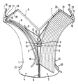
- the drawing shows the top view of a device according to the invention, the right half of the device shown showing the position of the elements when the storage compartment is completely filled and the left half showing the position of the components when the storage compartment is almost empty.
- the horizontal base plate 1 of the device shown is adapted in its outer contour to the course of the compartments and the components to be described.
- On this horizontal base plate 1 are two open at the top, for the upright reception of the objects 2 serving, elongated storage compartments 3 and 4 formed, which are bounded by two lateral side walls arranged on the base plate and curved in the same direction in an arcuate manner, as will be described in more detail below.
- the compartments end in the area of the outer edge of the base plate, in the drawing below, in a removal opening, the side walls of two storage surfaces each approaching in the direction of their removal opening in such a way that these storage compartments form an angle in their longitudinal extent and their removal openings lie next to one another, as in this represents the drawing.
- an M-shaped rear wall 5 is formed on the horizontal base plate 1.
- the mutually associated inner side walls of the compartments 3 and 4 are combined to form a common one-piece wall section 6, which thus forms the central partition between the two removal openings of the compartments 3 and 4.
- the wall section 6 is designed as a hollow body made of transparent plastic which is open at the top, specifically in a wedge shape with the apex directed towards the removal openings, as the drawing shows.
- the inner side walls 7 and 8 remaining to the rear of the wall section 6 are each pivotably mounted at the rear end of the one-piece wall section 6 about a stationary axis running perpendicular to the base plate 1 and spring-loaded in the direction of the compartment interior.
- the pivot axes are each formed by an inwardly curved formation 9, and the side walls 7 and 8 are each articulated to the associated formation 9 of the wall section 6 by a complementarily shaped outwardly curved formation 10.
- the shape and position of the projections 9 and 10 can be such can be chosen so that the inner curved portions of the projections 10 of the inner side walls 7 and 8 are supported against one another, so that the bearing is secured in this position.
- the inner side walls 7 and 8 with their formations 10 are pushed onto the formations 9 from above.
- a spreading common leaf spring 11 is provided, the free ends of which bear against the side walls 7 and 8.
- This leaf spring 11 is held on an extension 12 of the stationary vertical rear wall 5 arranged centrally between the side walls 7 and 8, namely the leaf spring 11 is snapped onto the center of a front thickening 13 of the extension 12.
- the outer side walls 14 and 15 of the compartments 3 and 4 are each pivoted at their rear end about a stationary axis running perpendicular to the base plate from a stop-limited external position (right half of the drawing) and spring-loaded towards the interior of the compartment .
- the pivot axes for the outer side walls 14 and 15 are formed by vertical peg-shaped projections 16 on the lateral ends of the rear wall 5, respectively.
- Each outer side wall 14 or 15 is snapped onto the projections 16 by means of a complementary recess 17 and held pivotably for the pivot bearing.
- the spring loading of the outer side walls 14 and 15 is achieved in the following way:
- the outer side walls 14 and 15 are each extended at the rear end beyond their pivot axis 16, 17, and it is Between the rear wall 5 and these extensions 18, a compression spring 19 is arranged, each of which is designed as a spreading leaf spring, the ends of which rest on the one hand on the extension 18 and on the other hand on the rear surface of the rear wall 5 and are held there.
- Simple recesses 20 can be provided for these holders in the rear surface of the rear wall 5 or in the extension 18.
- a stop projection 21 is formed upwards from the base plate 1.
- the rear wall 5 which is stationary on the base plate 1, is M-shaped in plan view, and it is the extension 12, 13 carrying the leaf spring 11 for the inner side walls 7 and 8 as an extension of the central apex of the rear wall formed with a peg-shaped projection 13 as a pivot axis.
- the leaf springs 19 for the outer side walls 14 and 15 are then each held on the outer legs of the rear wall 5.
- All components of the device with the exception of the leaf springs 11 and 19 are expediently molded from transparent plastic.
- the dimensioning of the respective height of the components can be adapted and dimensioned to the respective intended use.
- the height of the wall section 6, the side walls 7 and 8, the side walls 14 and 15 and the rear wall 5 can be dimensioned over the complete height of the objects to be set.
- Spring properties and thus also the width (perpendicular to the drawing the height) of the leaf springs 11 and 19 is also measured according to the application. All these dimensions can be adapted to the most difficult to handle objects for a variety of uses, in order to then display all other flat and flexible objects in the desired manner in the best possible way.
- the free ends of the outer side walls 14 and 15 can be curved outwards, as shown in the drawing.
- the free ends of the inner side walls 7 and 8 can also be provided with bends shown in the drawing to form a stop.
- the stationary side walls of the compartments 3 and 4 like the rear wall 5 on the base plate 1 and to make only the inner side walls 7 and 8 pivotable in the manner described under spring loading .
- the same components can then be used with respect to the pivotability of the inner side walls both for the illustrated embodiment and for the last-described embodiment with fixed outer side walls, which simplifies and simplifies manufacture and assembly.
Landscapes
- Packaging Of Annular Or Rod-Shaped Articles, Wearing Apparel, Cassettes, Or The Like (AREA)
- Supplying Of Containers To The Packaging Station (AREA)
- Vending Machines For Individual Products (AREA)
- Mirrors, Picture Frames, Photograph Stands, And Related Fastening Devices (AREA)
- Supports Or Holders For Household Use (AREA)
- Containers And Plastic Fillers For Packaging (AREA)
- Preparing Plates And Mask In Photomechanical Process (AREA)
- Cold Air Circulating Systems And Constructional Details In Refrigerators (AREA)
- Chair Legs, Seat Parts, And Backrests (AREA)
- Air Bags (AREA)
- Assembled Shelves (AREA)
- Displays For Variable Information Using Movable Means (AREA)
- Rigid Containers With Two Or More Constituent Elements (AREA)
Priority Applications (1)
| Application Number | Priority Date | Filing Date | Title |
|---|---|---|---|
| AT90116812T ATE83139T1 (de) | 1989-09-12 | 1990-09-01 | Vorrichtung zur schaustellung von flachen gegenstaenden. |
Applications Claiming Priority (2)
| Application Number | Priority Date | Filing Date | Title |
|---|---|---|---|
| DE8910867U DE8910867U1 (de) | 1989-09-12 | 1989-09-12 | Vorrichtung zur Schaustellung von flachen Gegenständen |
| DE8910867U | 1989-09-12 |
Publications (2)
| Publication Number | Publication Date |
|---|---|
| EP0417580A1 EP0417580A1 (de) | 1991-03-20 |
| EP0417580B1 true EP0417580B1 (de) | 1992-12-09 |
Family
ID=6842777
Family Applications (1)
| Application Number | Title | Priority Date | Filing Date |
|---|---|---|---|
| EP90116812A Expired - Lifetime EP0417580B1 (de) | 1989-09-12 | 1990-09-01 | Vorrichtung zur Schaustellung von flachen Gegenständen |
Country Status (10)
| Country | Link |
|---|---|
| US (1) | US5123544A (da) |
| EP (1) | EP0417580B1 (da) |
| AT (1) | ATE83139T1 (da) |
| DD (1) | DD297551A5 (da) |
| DE (2) | DE8910867U1 (da) |
| DK (1) | DK0417580T3 (da) |
| ES (1) | ES2036083T3 (da) |
| GR (1) | GR3007223T3 (da) |
| NO (1) | NO175183C (da) |
| PT (2) | PT95279A (da) |
Families Citing this family (3)
| Publication number | Priority date | Publication date | Assignee | Title |
|---|---|---|---|---|
| DE19701255A1 (de) * | 1997-01-16 | 1998-07-23 | Hannecke Wolf D Kunststoff | Vorrichtung zur Präsentation flacher oder biegsamer Gegenstände |
| US6651827B1 (en) * | 2000-11-02 | 2003-11-25 | Berol Corporation | Brochure holder |
| US6749071B2 (en) * | 2001-12-10 | 2004-06-15 | American Greetings Corporation | Merchandizing display |
Family Cites Families (11)
| Publication number | Priority date | Publication date | Assignee | Title |
|---|---|---|---|---|
| GB823070A (da) * | ||||
| US450747A (en) * | 1891-04-21 | Bag-holder | ||
| GB190516116A (en) * | 1905-08-08 | 1906-05-24 | Archer Alfred Round | An Improved Holder or Case for Tramcar and other Tickets. |
| US1949200A (en) * | 1932-07-16 | 1934-02-27 | Freson Frank | Display rack for periodicals |
| US2407119A (en) * | 1941-12-26 | 1946-09-03 | Weston Herbert | Accounting and filing system |
| US2488262A (en) * | 1947-09-22 | 1949-11-15 | Brookport Company | Article holder |
| US2912113A (en) * | 1959-03-30 | 1959-11-10 | Jack J Durec | Card holder |
| US3892309A (en) * | 1973-10-18 | 1975-07-01 | Ncr Co | Replaceable currency or bill holder for a till tray |
| DE8225277U1 (de) * | 1982-09-08 | 1982-12-02 | Hannecke, Wolf-Dietrich, 3410 Northeim | Vorrichtung zur schaustellung von flachen gegenstaenden |
| DE3311975C2 (de) * | 1983-03-31 | 1987-03-12 | Computer Gesellschaft Konstanz Mbh, 7750 Konstanz | Ablagefach in einer Belegverarbeitungseinrichtung |
| US4753369A (en) * | 1985-12-24 | 1988-06-28 | Marvin Glass & Associates | Napkin dispenser |
-
1989
- 1989-09-12 DE DE8910867U patent/DE8910867U1/de not_active Expired
-
1990
- 1990-08-27 US US07/573,546 patent/US5123544A/en not_active Expired - Lifetime
- 1990-09-01 DE DE9090116812T patent/DE59000571D1/de not_active Expired - Fee Related
- 1990-09-01 AT AT90116812T patent/ATE83139T1/de not_active IP Right Cessation
- 1990-09-01 EP EP90116812A patent/EP0417580B1/de not_active Expired - Lifetime
- 1990-09-01 DK DK90116812.0T patent/DK0417580T3/da active
- 1990-09-01 ES ES199090116812T patent/ES2036083T3/es not_active Expired - Lifetime
- 1990-09-11 DD DD90343953A patent/DD297551A5/de not_active IP Right Cessation
- 1990-09-11 NO NO903959A patent/NO175183C/no unknown
- 1990-09-11 PT PT95279A patent/PT95279A/pt active IP Right Grant
-
1991
- 1991-12-12 PT PT8410U patent/PT8410U/pt not_active IP Right Cessation
-
1993
- 1993-03-05 GR GR920402665T patent/GR3007223T3/el unknown
Also Published As
| Publication number | Publication date |
|---|---|
| US5123544A (en) | 1992-06-23 |
| DK0417580T3 (da) | 1993-02-01 |
| NO903959L (no) | 1991-03-13 |
| DE59000571D1 (de) | 1993-01-21 |
| NO175183C (no) | 1994-09-14 |
| DE8910867U1 (de) | 1989-11-02 |
| DD297551A5 (de) | 1992-01-16 |
| PT95279A (pt) | 1992-03-31 |
| GR3007223T3 (da) | 1993-07-30 |
| ATE83139T1 (de) | 1992-12-15 |
| EP0417580A1 (de) | 1991-03-20 |
| ES2036083T3 (es) | 1993-05-01 |
| NO175183B (da) | 1994-06-06 |
| NO903959D0 (no) | 1990-09-11 |
| PT8410U (pt) | 1994-09-30 |
| PT8410T (pt) | 1992-04-30 |
Similar Documents
| Publication | Publication Date | Title |
|---|---|---|
| DE2834329A1 (de) | Flaschenstaender | |
| DE3404561A1 (de) | Klammer, insbesondere waescheklammer | |
| DE2746118A1 (de) | Halter fuer informationstraeger in streifenform | |
| DE3900904C1 (da) | ||
| DE2427104C2 (de) | Halter für Magnetbandkassette | |
| DE2461347C2 (de) | Brillengestell | |
| EP0417580B1 (de) | Vorrichtung zur Schaustellung von flachen Gegenständen | |
| AT1240U1 (de) | Handstempel, stempelplatte hiefür und stempelplattengarnitur | |
| DE69619594T2 (de) | Vorrichtung zur Festhalten von Papierbögen, Dateien oder Lochkarten in Ordnern oder dergleichen | |
| DE60209857T2 (de) | Rotierender Kartenhalter | |
| DE3420608C2 (de) | Vorrichtung zur Halterung und Präsentation von in SB-Verpackungen befindlichen Waren | |
| DE3734649A1 (de) | Sportbrille | |
| DE69412765T2 (de) | Geschirr wie ein Tablett, Untertasse oder Teller für die Presentation einer Rechnung | |
| DE3021098A1 (de) | Regalwagen als putz- und arbeitswagen, insbesondere fuer krankenhaeuser und hotels | |
| DE2253982C2 (de) | Behälter zur Aufnahme und einzelweisen Ausgabe insbes. von Tabletten | |
| EP0084812B1 (de) | Skiabweiser | |
| DE1759502C3 (de) | Türflügel | |
| DE2444180A1 (de) | Staender fuer die aufstellung eines plakats | |
| DE7613077U1 (de) | Schublade fuer schubladenschraenke | |
| DE3011270A1 (de) | Vorrichtung, insbesondere behaelter, mit einem tragboden und daran angeordneten klappbeinen | |
| DE1148048B (de) | Aufhaenger fuer Schuhe | |
| DE4400882A1 (de) | Aktenordner | |
| DE8430168U1 (de) | Plakatkörper | |
| DE7612512U1 (de) | Halter fuer betaetigungsstangen von storen oder rollaeden | |
| DE1170592B (de) | Verschluss fuer Behaelter, Kassetten od. dgl. |
Legal Events
| Date | Code | Title | Description |
|---|---|---|---|
| PUAI | Public reference made under article 153(3) epc to a published international application that has entered the european phase |
Free format text: ORIGINAL CODE: 0009012 |
|
| 17P | Request for examination filed |
Effective date: 19901221 |
|
| AK | Designated contracting states |
Kind code of ref document: A1 Designated state(s): AT BE CH DE DK ES FR GB GR IT LI LU NL SE |
|
| 17Q | First examination report despatched |
Effective date: 19920416 |
|
| GRAA | (expected) grant |
Free format text: ORIGINAL CODE: 0009210 |
|
| AK | Designated contracting states |
Kind code of ref document: B1 Designated state(s): AT BE CH DE DK ES FR GB GR IT LI LU NL SE |
|
| REF | Corresponds to: |
Ref document number: 83139 Country of ref document: AT Date of ref document: 19921215 Kind code of ref document: T |
|
| GBT | Gb: translation of ep patent filed (gb section 77(6)(a)/1977) |
Effective date: 19921207 |
|
| REF | Corresponds to: |
Ref document number: 59000571 Country of ref document: DE Date of ref document: 19930121 |
|
| REG | Reference to a national code |
Ref country code: DK Ref legal event code: T3 |
|
| ITF | It: translation for a ep patent filed | ||
| ET | Fr: translation filed | ||
| REG | Reference to a national code |
Ref country code: ES Ref legal event code: FG2A Ref document number: 2036083 Country of ref document: ES Kind code of ref document: T3 |
|
| REG | Reference to a national code |
Ref country code: GR Ref legal event code: FG4A Free format text: 3007223 |
|
| PLBE | No opposition filed within time limit |
Free format text: ORIGINAL CODE: 0009261 |
|
| STAA | Information on the status of an ep patent application or granted ep patent |
Free format text: STATUS: NO OPPOSITION FILED WITHIN TIME LIMIT |
|
| 26N | No opposition filed | ||
| EPTA | Lu: last paid annual fee | ||
| PGFP | Annual fee paid to national office [announced via postgrant information from national office to epo] |
Ref country code: LU Payment date: 19940801 Year of fee payment: 5 |
|
| PGFP | Annual fee paid to national office [announced via postgrant information from national office to epo] |
Ref country code: SE Payment date: 19940822 Year of fee payment: 5 |
|
| PGFP | Annual fee paid to national office [announced via postgrant information from national office to epo] |
Ref country code: CH Payment date: 19940906 Year of fee payment: 5 |
|
| PGFP | Annual fee paid to national office [announced via postgrant information from national office to epo] |
Ref country code: ES Payment date: 19940914 Year of fee payment: 5 |
|
| PGFP | Annual fee paid to national office [announced via postgrant information from national office to epo] |
Ref country code: GR Payment date: 19940916 Year of fee payment: 5 |
|
| PGFP | Annual fee paid to national office [announced via postgrant information from national office to epo] |
Ref country code: BE Payment date: 19940927 Year of fee payment: 5 Ref country code: DK Payment date: 19940927 Year of fee payment: 5 |
|
| PGFP | Annual fee paid to national office [announced via postgrant information from national office to epo] |
Ref country code: NL Payment date: 19940930 Year of fee payment: 5 |
|
| EAL | Se: european patent in force in sweden |
Ref document number: 90116812.0 |
|
| PG25 | Lapsed in a contracting state [announced via postgrant information from national office to epo] |
Ref country code: LU Free format text: LAPSE BECAUSE OF NON-PAYMENT OF DUE FEES Effective date: 19950901 Ref country code: DK Effective date: 19950901 |
|
| REG | Reference to a national code |
Ref country code: DK Ref legal event code: EBP |
|
| PG25 | Lapsed in a contracting state [announced via postgrant information from national office to epo] |
Ref country code: SE Effective date: 19950902 Ref country code: ES Free format text: LAPSE BECAUSE OF EXPIRATION OF PROTECTION Effective date: 19950902 |
|
| PG25 | Lapsed in a contracting state [announced via postgrant information from national office to epo] |
Ref country code: CH Effective date: 19950930 Ref country code: BE Effective date: 19950930 Ref country code: LI Effective date: 19950930 |
|
| BERE | Be: lapsed |
Owner name: WOLF-DIETRICH HANNECKE KUNSTSTOFFTECHNIK Effective date: 19950930 |
|
| PG25 | Lapsed in a contracting state [announced via postgrant information from national office to epo] |
Ref country code: GR Free format text: THE PATENT HAS BEEN ANNULLED BY A DECISION OF A NATIONAL AUTHORITY Effective date: 19960331 |
|
| PG25 | Lapsed in a contracting state [announced via postgrant information from national office to epo] |
Ref country code: NL Effective date: 19960401 |
|
| REG | Reference to a national code |
Ref country code: CH Ref legal event code: PL |
|
| REG | Reference to a national code |
Ref country code: GR Ref legal event code: MM2A Free format text: 3007223 |
|
| NLV4 | Nl: lapsed or anulled due to non-payment of the annual fee |
Effective date: 19960401 |
|
| EUG | Se: european patent has lapsed |
Ref document number: 90116812.0 |
|
| REG | Reference to a national code |
Ref country code: ES Ref legal event code: FD2A Effective date: 19990601 |
|
| REG | Reference to a national code |
Ref country code: GB Ref legal event code: IF02 |
|
| PGFP | Annual fee paid to national office [announced via postgrant information from national office to epo] |
Ref country code: AT Payment date: 20080826 Year of fee payment: 19 Ref country code: IT Payment date: 20080918 Year of fee payment: 19 Ref country code: FR Payment date: 20080828 Year of fee payment: 19 |
|
| PGFP | Annual fee paid to national office [announced via postgrant information from national office to epo] |
Ref country code: GB Payment date: 20080903 Year of fee payment: 19 |
|
| PGFP | Annual fee paid to national office [announced via postgrant information from national office to epo] |
Ref country code: DE Payment date: 20080913 Year of fee payment: 19 |
|
| GBPC | Gb: european patent ceased through non-payment of renewal fee |
Effective date: 20090901 |
|
| REG | Reference to a national code |
Ref country code: FR Ref legal event code: ST Effective date: 20100531 |
|
| PG25 | Lapsed in a contracting state [announced via postgrant information from national office to epo] |
Ref country code: AT Free format text: LAPSE BECAUSE OF NON-PAYMENT OF DUE FEES Effective date: 20090901 |
|
| PG25 | Lapsed in a contracting state [announced via postgrant information from national office to epo] |
Ref country code: FR Free format text: LAPSE BECAUSE OF NON-PAYMENT OF DUE FEES Effective date: 20090930 Ref country code: DE Free format text: LAPSE BECAUSE OF NON-PAYMENT OF DUE FEES Effective date: 20100401 |
|
| PG25 | Lapsed in a contracting state [announced via postgrant information from national office to epo] |
Ref country code: GB Free format text: LAPSE BECAUSE OF NON-PAYMENT OF DUE FEES Effective date: 20090901 |
|
| PG25 | Lapsed in a contracting state [announced via postgrant information from national office to epo] |
Ref country code: IT Free format text: LAPSE BECAUSE OF NON-PAYMENT OF DUE FEES Effective date: 20090901 |