EP0417636B1 - Bogenausleger für eine Offsetdruckmaschine für Bahnen - Google Patents
Bogenausleger für eine Offsetdruckmaschine für Bahnen Download PDFInfo
- Publication number
- EP0417636B1 EP0417636B1 EP90117144A EP90117144A EP0417636B1 EP 0417636 B1 EP0417636 B1 EP 0417636B1 EP 90117144 A EP90117144 A EP 90117144A EP 90117144 A EP90117144 A EP 90117144A EP 0417636 B1 EP0417636 B1 EP 0417636B1
- Authority
- EP
- European Patent Office
- Prior art keywords
- paper
- low
- speed belt
- snubber
- speed
- Prior art date
- Legal status (The legal status is an assumption and is not a legal conclusion. Google has not performed a legal analysis and makes no representation as to the accuracy of the status listed.)
- Expired - Lifetime
Links
Images


Classifications
-
- B—PERFORMING OPERATIONS; TRANSPORTING
- B65—CONVEYING; PACKING; STORING; HANDLING THIN OR FILAMENTARY MATERIAL
- B65H—HANDLING THIN OR FILAMENTARY MATERIAL, e.g. SHEETS, WEBS, CABLES
- B65H29/00—Delivering or advancing articles from machines; Advancing articles to or into piles
- B65H29/66—Advancing articles in overlapping streams
- B65H29/6609—Advancing articles in overlapping streams forming an overlapping stream
- B65H29/6618—Advancing articles in overlapping streams forming an overlapping stream upon transfer from a first conveyor to a second conveyor advancing at slower speed
-
- B—PERFORMING OPERATIONS; TRANSPORTING
- B65—CONVEYING; PACKING; STORING; HANDLING THIN OR FILAMENTARY MATERIAL
- B65H—HANDLING THIN OR FILAMENTARY MATERIAL, e.g. SHEETS, WEBS, CABLES
- B65H29/00—Delivering or advancing articles from machines; Advancing articles to or into piles
- B65H29/68—Reducing the speed of articles as they advance
Definitions
- This invention relates to a paper delivery for a web offset printing press of a type which discharges paper by shiftedly stacking paper by retardation on a low-speed belt, like a sheeter.
- a rolled web offset printing press is provided with a folder which cuts the web, which is printed, dried and cooled, to a predetermined length, or folds it in the cross or longitudinal direction of the web.
- the completed signature which is intermittently fed has been dropped one by one between blades of a fan wheel, rotated, and dropped on a delivery conveyor to be discharged in a shiftedly stacked state.
- the inventors formerly invented a paper delivery which utilizes a sheeter to cut the web into cut sheets and stack them, thereby increasing the speed of the folder.
- a snubber for regulating the vertical relative positions of the foregoing signature and following signature to make paper dodging and retarding the signature by snapping the rear end of the signature between the snubber and the low-speed belt, and a braking roller for retarding the signature down to the speed of the low-speed belt to shiftedly stack the signatures. Furthermore, the outlet side of an upper one of a pair of high-speed belts is overlapped above the inlet side of the low-speed belt.
- the signature tends to strongly hit the braking roller resulting in a damage at the front edge, or the signature tends to be strongly nipped instantaneously between the snubber and the low-speed belt resulting in scratch marks at the rear end of the signature.
- the braking roller is moved towards the paper delivery direction, paper dodging between signatures becomes impossible resulting in paper jamming, or, when the rear end of the signature is caused not to be nipped in order to eliminate scratching with the snubber, the unretarded signature hits the braking roller resulting in increased damages to the front edge. Consequently, the signatures can be handled at a rate of no more than 600 units per minute even if a best condition is set where no flaws or damages are caused on the signatures.
- GB-A-1 580 056 discloses also a preliminary slow-down unit for a sheeting machine for slowing the rate of travel of sheets between the cutter and the delivery end of such a machine. It comprises a snubber for maintaining a constant positional relation between the preceding paper and the next paper.
- the invention provides a paper delivery for a web offset printing press comprising the features of claim 1.
- Fig.1 is a schematic side cross sectional view of a folder showing an embodiment of the present invention.
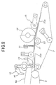
- Fig.2 is a schematic enlarged side view showing part of Fig.1.
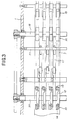
- Fig.3 is a schematic cross sectional view of Fig.2.
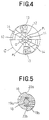
- Fig.4 is a schematic side view of a snubber used in this embodiment.
- Fig.5 is a schematic side view of a slowdown member used in this embodiment.
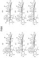
- Figs.6(A) through 6(F) are schematic views showing operations of the snubber in this embodiment.
- Fig.7 is a schematic side cross sectional view of a snubber of another embodiment of the present invention.
- a plurality of the low-speed belts 7 are disposed between the right and left main frames 1, 1, and the outlet side of an upper high-speed belt 6a of the pair of high-speed belts 6 is overlapped above with the inlet side of the low-speed belts 7 over a predetermined length.
- a snubber 10 for maintaining the vertical relation between the preceding paper and the next paper is disposed above the inlet side of the low-speed belt 7.
- the snubber 10 as shown in Fig.4, is mounted with wheels 13 through an arm 12 at symmetrical positions on the outer periphery of a rotary shaft 11, and guide plates 14 having arc-formed outer peripheral surfaces are mounted at both ends of the arm 12 and in front of the wheels 13 with respect to the rotational direction.
- Centers P1 and P2 of arc of the guide plates 14 are slightly offset from a center O of rotation of the snubber 10, so that the outer peripheral surface of the guide plates 14 gradually withdraws inside from the rotational locus C of the largest-diameter portion of the snubber 10 towards the front side of the rotational direction.
- the peripheral speed of the largest-diameter portion of the snubber 10 is set a little smaller than the speed of the signature.
- a braking roller 15 for retarding the signature and shiftedly stacking them on the low-speed belt 7 is disposed between the right and left main frames 1, 1.
- the slowdown member 16 as shown in Fig.5, comprises semicircular rings 19a and 19b placed opposite one another with an offset in the radial direction of the rotary shaft 18, and the protruded portions form claws 20a and 20b.
- the paper guide 17 comprises a plurality of elongate rectangular plates supported by a supporting plate 21 disposed between the right and left main frames 1, 1.
- the paper guide 17 is disposed so as to guide the signature to the slowdown member 16 and to the braking roller 15.
- a deflection roller 22 and first and second conveyor tables 23a and 23 b as guide means to urge the low-speed belt 7 towards the slowdown member 16 side are disposed at the opposite side of the slowdown pulley 16 across the low-speed belt 7.
- former-folded web passes through the nipping rollers 2, 2, and cut by the cut-off cylinder 4 to a predetermined length to form signatures, and the signatures are transported by the high-speed belts 6 with a predetermined pitch to be supplied onto the low-speed belt 7.
- a signature A1 is gradually dropped onto the low-speed belt 7 (Fig.6(A) and Fig.6(B)), the leading edge of the signature A1 is guided by the paper guide 17 and the low-speed belt 7 to contact against the slowdown member 16, thereby achieving primary retardation and leading edge registration of the signature A1.
- the rear end of the signature is dodged with the next signature A2 (Fig.6(C) and Fig.6(D)).
- the signature A1 which is primary-retarded within a predetermined section indicated by an angle ⁇ is guided by the paper guide 17 to the braking roller 15, where it is finally retarded to the transportation speed of the low-speed belt 7 (Fig.6(E) and Fig.6(F).
- This procedure is continued to shiftedly stack a predetermined number of signatures on the low-speed belt 7, which are discharged.
- the signature is primary-retarded by the slowdown pulley 16 prior to the braking roller 15, impact of the leading edge of the signature to the braking roller 15 is decreased, thereby preventing the leading edge of the signature from being damaged. Furthermore, with such two-step retardation, it is not necessary to retard the signature by nipping the rear end of the signature between the wheel 13 of the snubber 10 and the low-speed belt 7, and a clearance can be always set between the snubber 10 and the low-speed belt 7, thereby preventing the rear end of the signature from being scratched by the snubber 10.
- the guide plate 14 of the snubber 10 gradually protrudes from the upper high-speed belt 6a to begin peeling the signature from the upper high-speed belt 6a (Fig.6(B)) and the outer peripheral surface of the guide plate 14 is arc-formed, the signature is smoothly peeled off from the upper high-speed belt and dropped down onto the low-speed belt 7.
- the rear end of the signature is also completely dropped down onto the low-speed belt, thereby allowing good dodging with the front end of the next signature (Fig.6(E)).
- Fig.7 shows another embodiment of the present invention.
- a plurality of rollers 25 are supported by adequate means at both ends of the arm 12, so that the centers P3 and P4 of circumcircles of the rollers 25 are slightly offset of the rotational center O of the snubber 10.
- the present invention is described above using a folder as a delivery. However, it is needless to say that the present invention can also be applied to sheeters having the similar arrangement which make merely cutting without folding, to obtain the same functions and effects.
Landscapes
- Engineering & Computer Science (AREA)
- Mechanical Engineering (AREA)
- Separation, Sorting, Adjustment, Or Bending Of Sheets To Be Conveyed (AREA)
- Rotary Presses (AREA)
- Registering, Tensioning, Guiding Webs, And Rollers Therefor (AREA)
- Handling Of Continuous Sheets Of Paper (AREA)
Claims (4)
- Bogenausleger für eine Offsetdruckmaschine für Bahnen, mit:
einem langsamlaufenden Gurt (7) zum Bogentransport,
einem Paar oberen und unteren schnellaufenden Gurten (6a, 6), wobei die Abgabeseite des oberen schnellaufenden Gurtes (6a) die Aufnahmeseite des langsamlaufenden Gurtes (7) für die Bogenzufuhr überlappt,
einem Dämpfer zum Aufrechterhalten einer konstanten Beziehung zwischen einem vorhergehenden Bogen und einem nachfolgenden Bogen,
einer Bremswalze (15) oberhalb der Abgabeseite des langsamlaufenden Gurtes (7) zum versetzten Stapeln von Bögen auf dem langsamlaufenden Gurt (7),
einem Verzögerungselement (16) oberhalb des langsamlaufenden Gurtes (7) zwischen dem Dämpfer (10) und der Bremswalze (15) zur primären Verlangsamung von Bögen, und mit
einem Leitmittel (17) zum Leiten von Bögen zum Verzögerungselement (16),
dadurch gekennzeichnet, daß
der Dämpfer (10) oberhalb der Aufnahmeseite des langsamlaufenden Gurtes (7) angeordnet ist, wobei ein Abstand zwischen dem Dämpfer (10) und dem langsamlaufenden Gurt (7) besteht, und daß
das Verzögerungselement (16) vorstehende Abschnitte (20a, 20b) hat, die Klauen bilden. - Bogenausleger für eine Offsetdruckmaschine für Bahnen nach Anspruch 1, wobei das Verzögerungselement (16) eine rotierende Welle (18) hat und eine Mehrzahl von vorstehenden Abschnitten (20a, 20b) längs der rotierenden Welle (18) angeordnet ist.
- Bogenausleger nach Anspruch 1, wobei das Verzögerungselement (16) halbkreisförmige Ringe (19a, 19b) aufweist, die auf dem äußeren Umfang der rotierenden Welle (18) mit einem Versatz in der radialen Richtung der rotierenden Welle einander gegenüberliegen, und deren vorstehende Abschnitte Klauen (20a, 20b) bilden.
- Bogenausleger nach Anspruch 1, wobei das Leitmittel (17) eine Anzahl länglicher, rechteckiger Platten umfaßt, die von einer Trägerplatte getragen werden, die zwischen rechten und linken Hauptrahmen angeordnet ist.
Priority Applications (1)
| Application Number | Priority Date | Filing Date | Title |
|---|---|---|---|
| EP94250035A EP0602023B1 (de) | 1989-09-12 | 1990-09-06 | Bogenausleger für eine Offsetdruckmaschine für Bahnen |
Applications Claiming Priority (4)
| Application Number | Priority Date | Filing Date | Title |
|---|---|---|---|
| JP23471689 | 1989-09-12 | ||
| JP234716/89 | 1989-09-12 | ||
| JP265124/89 | 1989-10-13 | ||
| JP1265124A JP2708243B2 (ja) | 1989-09-12 | 1989-10-13 | 輪転印刷機の排紙装置 |
Related Child Applications (1)
| Application Number | Title | Priority Date | Filing Date |
|---|---|---|---|
| EP94250035.6 Division-Into | 1990-09-06 |
Publications (3)
| Publication Number | Publication Date |
|---|---|
| EP0417636A2 EP0417636A2 (de) | 1991-03-20 |
| EP0417636A3 EP0417636A3 (en) | 1991-12-11 |
| EP0417636B1 true EP0417636B1 (de) | 1996-05-01 |
Family
ID=26531720
Family Applications (2)
| Application Number | Title | Priority Date | Filing Date |
|---|---|---|---|
| EP90117144A Expired - Lifetime EP0417636B1 (de) | 1989-09-12 | 1990-09-06 | Bogenausleger für eine Offsetdruckmaschine für Bahnen |
| EP94250035A Expired - Lifetime EP0602023B1 (de) | 1989-09-12 | 1990-09-06 | Bogenausleger für eine Offsetdruckmaschine für Bahnen |
Family Applications After (1)
| Application Number | Title | Priority Date | Filing Date |
|---|---|---|---|
| EP94250035A Expired - Lifetime EP0602023B1 (de) | 1989-09-12 | 1990-09-06 | Bogenausleger für eine Offsetdruckmaschine für Bahnen |
Country Status (5)
| Country | Link |
|---|---|
| US (1) | US5088719A (de) |
| EP (2) | EP0417636B1 (de) |
| JP (1) | JP2708243B2 (de) |
| AT (2) | ATE147703T1 (de) |
| DE (2) | DE69026778T2 (de) |
Families Citing this family (6)
| Publication number | Priority date | Publication date | Assignee | Title |
|---|---|---|---|---|
| JP2516640Y2 (ja) * | 1990-06-25 | 1996-11-06 | 株式会社小森コーポレーション | 紙かわし装置 |
| US5265862A (en) * | 1992-09-25 | 1993-11-30 | Numerical Concepts, Inc. | Sheeter for recycled and lightweight paper stocks |
| US5997460A (en) * | 1998-01-29 | 1999-12-07 | Young; Alan D. | Inline delivery vehicle for a web offset printing press |
| US6231044B1 (en) | 1998-12-29 | 2001-05-15 | Quad/Tech, Inc. | Delivery apparatus for a printing press |
| US6394445B1 (en) | 1998-12-30 | 2002-05-28 | Quad/Tech, Inc. | Apparatus for slowing down and guiding a signature and method for doing the same |
| EP4699969A1 (de) * | 2024-08-20 | 2026-02-25 | FOSBER S.p.A. | Überlappungsvorrichtung und bogenproduktionslinie mit der überlappungsvorrichtung |
Citations (1)
| Publication number | Priority date | Publication date | Assignee | Title |
|---|---|---|---|---|
| EP0244650A2 (de) * | 1986-04-04 | 1987-11-11 | Littleton Industrial Consultants, Inc. | System zum Ablenken und zum Ausgeben von Bögen |
Family Cites Families (9)
| Publication number | Priority date | Publication date | Assignee | Title |
|---|---|---|---|---|
| DE2348320C3 (de) * | 1973-09-26 | 1978-12-14 | Vits-Maschinenbau Gmbh, 4018 Langenfeld | Vorrichtung zum stapelweisen Ablegen einzelner gleichlanger Bogen |
| DE2725547C2 (de) * | 1977-06-07 | 1983-12-22 | De La Rue Giori S.A., 1003 Lausanne | Verfahren und Vorrichtung zum fächerartigen Übereinanderschieben von bogen- oder heftförmigen Gegenständen |
| GB1580056A (en) * | 1977-07-12 | 1980-11-26 | Drg Uk Ltd | Slow-down on sheeting machines |
| US4436302A (en) * | 1981-05-28 | 1984-03-13 | Beloit Corporation | Apparatus for slowing down and preventing edge damage on moving sheets |
| JPS61189050U (de) * | 1985-05-15 | 1986-11-25 | ||
| US4919027A (en) * | 1986-04-04 | 1990-04-24 | Littleton Industrial Consultants, Inc. | Sheet diverting and delivery system |
| US4969640A (en) * | 1986-04-04 | 1990-11-13 | Littleton Industrial Consultants, Inc. | Sweet diverting and delivery system |
| JPH0176847U (de) * | 1987-11-12 | 1989-05-24 | ||
| DE3836604A1 (de) * | 1988-10-27 | 1990-05-03 | Hilmar Vits | Querschneider fuer materialbahnen mit nachgeordneter ablage fuer die geschnittenen bogen |
-
1989
- 1989-10-13 JP JP1265124A patent/JP2708243B2/ja not_active Expired - Fee Related
-
1990
- 1990-09-05 US US07/579,070 patent/US5088719A/en not_active Expired - Fee Related
- 1990-09-06 EP EP90117144A patent/EP0417636B1/de not_active Expired - Lifetime
- 1990-09-06 AT AT94250035T patent/ATE147703T1/de not_active IP Right Cessation
- 1990-09-06 EP EP94250035A patent/EP0602023B1/de not_active Expired - Lifetime
- 1990-09-06 AT AT90117144T patent/ATE137475T1/de not_active IP Right Cessation
- 1990-09-06 DE DE69026778T patent/DE69026778T2/de not_active Expired - Fee Related
- 1990-09-06 DE DE69029746T patent/DE69029746T2/de not_active Expired - Fee Related
Patent Citations (1)
| Publication number | Priority date | Publication date | Assignee | Title |
|---|---|---|---|---|
| EP0244650A2 (de) * | 1986-04-04 | 1987-11-11 | Littleton Industrial Consultants, Inc. | System zum Ablenken und zum Ausgeben von Bögen |
Also Published As
| Publication number | Publication date |
|---|---|
| ATE137475T1 (de) | 1996-05-15 |
| EP0602023B1 (de) | 1997-01-15 |
| EP0417636A3 (en) | 1991-12-11 |
| EP0602023A1 (de) | 1994-06-15 |
| DE69026778D1 (de) | 1996-06-05 |
| JPH03186560A (ja) | 1991-08-14 |
| DE69029746T2 (de) | 1997-05-07 |
| DE69026778T2 (de) | 1996-10-02 |
| JP2708243B2 (ja) | 1998-02-04 |
| US5088719A (en) | 1992-02-18 |
| EP0417636A2 (de) | 1991-03-20 |
| DE69029746D1 (de) | 1997-02-27 |
| ATE147703T1 (de) | 1997-02-15 |
Similar Documents
| Publication | Publication Date | Title |
|---|---|---|
| US5452886A (en) | Device for slowing down signatures in a folding machine | |
| JPS605501B2 (ja) | シ−ト取扱い装置 | |
| US4088314A (en) | Synchronous stacking device | |
| US20070270297A1 (en) | Folding apparatus in a web-fed rotary printing press | |
| US5647586A (en) | Method and apparatus for decelerating a flat product | |
| US4565363A (en) | Apparatus for accurately spacing a sequence of shingled paper sheet products on a conveyor | |
| JP2516640Y2 (ja) | 紙かわし装置 | |
| JP2000505767A (ja) | 枚葉紙処理機 | |
| US5039082A (en) | Double slow down pinless and gripperless delivery system | |
| EP0602023B1 (de) | Bogenausleger für eine Offsetdruckmaschine für Bahnen | |
| JPH0223145A (ja) | 排紙装置 | |
| US5615878A (en) | Method and apparatus for accelerating and diverting flat products | |
| US5236188A (en) | Apparatus and method for delivering printed products in a rotary printing press | |
| US6247692B1 (en) | Signature delivery apparatus including two rotating buckets | |
| US6561507B1 (en) | Apparatus for decelerating and shingling signatures | |
| US4349188A (en) | Re-registering feeder and method of registering | |
| US5359929A (en) | Device for delivering signatures in a printing press | |
| EP0718226B1 (de) | Umlenkungsvorrichtung zum Zuführen von mindestens teilweise gefalteten Zeitungen oder Zeitschriften | |
| US5359930A (en) | Device for aligning flies for a printing press | |
| CA2238584A1 (en) | Non-marking slow-down apparatus | |
| US4093206A (en) | Folding device for roller rotating printing presses | |
| JPH0325390B2 (de) | ||
| JPH0772048B2 (ja) | 輪転印刷機の折機 | |
| JPS5931632Y2 (ja) | 紙折装置 | |
| JPH04341453A (ja) | 巻取紙印刷機のための折り装置 |
Legal Events
| Date | Code | Title | Description |
|---|---|---|---|
| PUAI | Public reference made under article 153(3) epc to a published international application that has entered the european phase |
Free format text: ORIGINAL CODE: 0009012 |
|
| 17P | Request for examination filed |
Effective date: 19901214 |
|
| AK | Designated contracting states |
Kind code of ref document: A2 Designated state(s): AT CH DE FR GB IT LI NL SE |
|
| PUAL | Search report despatched |
Free format text: ORIGINAL CODE: 0009013 |
|
| AK | Designated contracting states |
Kind code of ref document: A3 Designated state(s): AT CH DE FR GB IT LI NL SE |
|
| 17Q | First examination report despatched |
Effective date: 19931015 |
|
| GRAH | Despatch of communication of intention to grant a patent |
Free format text: ORIGINAL CODE: EPIDOS IGRA |
|
| GRAA | (expected) grant |
Free format text: ORIGINAL CODE: 0009210 |
|
| AK | Designated contracting states |
Kind code of ref document: B1 Designated state(s): AT CH DE FR GB IT LI NL SE |
|
| REF | Corresponds to: |
Ref document number: 137475 Country of ref document: AT Date of ref document: 19960515 Kind code of ref document: T |
|
| ITF | It: translation for a ep patent filed | ||
| REF | Corresponds to: |
Ref document number: 69026778 Country of ref document: DE Date of ref document: 19960605 |
|
| ET | Fr: translation filed | ||
| PLBE | No opposition filed within time limit |
Free format text: ORIGINAL CODE: 0009261 |
|
| STAA | Information on the status of an ep patent application or granted ep patent |
Free format text: STATUS: NO OPPOSITION FILED WITHIN TIME LIMIT |
|
| 26N | No opposition filed | ||
| PGFP | Annual fee paid to national office [announced via postgrant information from national office to epo] |
Ref country code: DE Payment date: 20010828 Year of fee payment: 12 |
|
| PGFP | Annual fee paid to national office [announced via postgrant information from national office to epo] |
Ref country code: GB Payment date: 20010905 Year of fee payment: 12 |
|
| PGFP | Annual fee paid to national office [announced via postgrant information from national office to epo] |
Ref country code: SE Payment date: 20010906 Year of fee payment: 12 |
|
| PGFP | Annual fee paid to national office [announced via postgrant information from national office to epo] |
Ref country code: FR Payment date: 20010911 Year of fee payment: 12 |
|
| PGFP | Annual fee paid to national office [announced via postgrant information from national office to epo] |
Ref country code: AT Payment date: 20010912 Year of fee payment: 12 |
|
| PGFP | Annual fee paid to national office [announced via postgrant information from national office to epo] |
Ref country code: CH Payment date: 20010914 Year of fee payment: 12 |
|
| PGFP | Annual fee paid to national office [announced via postgrant information from national office to epo] |
Ref country code: NL Payment date: 20010927 Year of fee payment: 12 |
|
| REG | Reference to a national code |
Ref country code: GB Ref legal event code: IF02 |
|
| PG25 | Lapsed in a contracting state [announced via postgrant information from national office to epo] |
Ref country code: GB Free format text: LAPSE BECAUSE OF NON-PAYMENT OF DUE FEES Effective date: 20020906 Ref country code: AT Free format text: LAPSE BECAUSE OF NON-PAYMENT OF DUE FEES Effective date: 20020906 |
|
| PG25 | Lapsed in a contracting state [announced via postgrant information from national office to epo] |
Ref country code: SE Free format text: LAPSE BECAUSE OF NON-PAYMENT OF DUE FEES Effective date: 20020907 |
|
| PG25 | Lapsed in a contracting state [announced via postgrant information from national office to epo] |
Ref country code: LI Free format text: LAPSE BECAUSE OF NON-PAYMENT OF DUE FEES Effective date: 20020930 Ref country code: CH Free format text: LAPSE BECAUSE OF NON-PAYMENT OF DUE FEES Effective date: 20020930 |
|
| PG25 | Lapsed in a contracting state [announced via postgrant information from national office to epo] |
Ref country code: NL Free format text: LAPSE BECAUSE OF NON-PAYMENT OF DUE FEES Effective date: 20030401 Ref country code: DE Free format text: LAPSE BECAUSE OF NON-PAYMENT OF DUE FEES Effective date: 20030401 |
|
| GBPC | Gb: european patent ceased through non-payment of renewal fee |
Effective date: 20020906 |
|
| EUG | Se: european patent has lapsed | ||
| REG | Reference to a national code |
Ref country code: CH Ref legal event code: PL |
|
| PG25 | Lapsed in a contracting state [announced via postgrant information from national office to epo] |
Ref country code: FR Free format text: LAPSE BECAUSE OF NON-PAYMENT OF DUE FEES Effective date: 20030603 |
|
| REG | Reference to a national code |
Ref country code: FR Ref legal event code: ST |
|
| PG25 | Lapsed in a contracting state [announced via postgrant information from national office to epo] |
Ref country code: IT Free format text: LAPSE BECAUSE OF NON-PAYMENT OF DUE FEES;WARNING: LAPSES OF ITALIAN PATENTS WITH EFFECTIVE DATE BEFORE 2007 MAY HAVE OCCURRED AT ANY TIME BEFORE 2007. THE CORRECT EFFECTIVE DATE MAY BE DIFFERENT FROM THE ONE RECORDED. Effective date: 20050906 |