EP0417641A2 - Elektronenstrahlerzeuger, insbesondere für eine Elektronenstrahlkanone - Google Patents
Elektronenstrahlerzeuger, insbesondere für eine Elektronenstrahlkanone Download PDFInfo
- Publication number
- EP0417641A2 EP0417641A2 EP90117159A EP90117159A EP0417641A2 EP 0417641 A2 EP0417641 A2 EP 0417641A2 EP 90117159 A EP90117159 A EP 90117159A EP 90117159 A EP90117159 A EP 90117159A EP 0417641 A2 EP0417641 A2 EP 0417641A2
- Authority
- EP
- European Patent Office
- Prior art keywords
- voltage
- electron beam
- voltage cable
- generator
- protective resistor
- Prior art date
- Legal status (The legal status is an assumption and is not a legal conclusion. Google has not performed a legal analysis and makes no representation as to the accuracy of the status listed.)
- Granted
Links
Images
Classifications
-
- H—ELECTRICITY
- H01—ELECTRIC ELEMENTS
- H01J—ELECTRIC DISCHARGE TUBES OR DISCHARGE LAMPS
- H01J37/00—Discharge tubes with provision for introducing objects or material to be exposed to the discharge, e.g. for the purpose of examination or processing thereof
- H01J37/02—Details
- H01J37/248—Components associated with high voltage supply
-
- H—ELECTRICITY
- H02—GENERATION; CONVERSION OR DISTRIBUTION OF ELECTRIC POWER
- H02H—EMERGENCY PROTECTIVE CIRCUIT ARRANGEMENTS
- H02H7/00—Emergency protective circuit arrangements specially adapted for specific types of electric machines or apparatus or for sectionalised protection of cable or line systems, and effecting automatic switching in the event of an undesired change from normal working conditions
Definitions
- the invention relates to an electron beam generator, in particular for an electron beam gun, with a hot cathode and a control electrode, which are arranged on a high-voltage insulator and can be connected to a high-voltage generator with a single-pole high-voltage cable, an insulating transformer for converting the cathode heating current having its primary winding on the high-voltage insulator Earth potential is.
- An electron beam generator of this type is known from DE-OS 33 33 686 for an electron beam gun for heating materials, in particular for welding.
- a multi-pole high-voltage cable with the associated multi-pole plug connections is no longer required due to the constructive combination of the beam head with a complete auxiliary voltage transmission, so that above all the ohmic line losses due to the heating current become almost zero.
- the power to be transmitted is considerably reduced and the volume of the insulating transformers is no longer transmitted by the performance but only determined by the necessary insulation distances.
- the isolation transformers are fed to earth potential and the control voltages are supplied via multiple plugs at the low voltage potential of the beam head.
- the object is achieved in that the single-pole high-voltage cable connected to the high-voltage connection is terminated at its connection ends with protective resistors, the impedance of which corresponds to or is adapted to the characteristic impedance of the high-voltage cable.
- the arrangement of protective resistors according to the invention prevents reflections and traveling waves in the event of high-voltage flashovers in the electron beam generator, and thus considerably reduces repercussions on the high-voltage generator. This has the consequence that insulation and component damage in the high voltage generator and in the entire electrical equipment of the electron beam system are significantly reduced and the operational safety of the system is thus significantly improved.
- the invention further enables the use of long high-voltage cables without affecting the operational safety of the system.
- the protective resistor has a higher ohmic resistance.
- the arrangement of the protective resistor according to the invention is explained in more detail with the aid of the circuit diagram shown in the drawing.
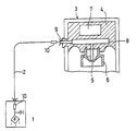
- the drawing shows the high-voltage generator 1 which is connected to the beam head 3 of an electron beam generator via a single-pole high-voltage cable 2.
- the beam head 3 contains a high-voltage insulator 4, which carries a cathode 5 and a control electrode 6.
- the high-voltage insulator 4 there is an insulating transformer 7, the primary winding of which is at ground potential and which serves as a current transformer for the cathode current.
- 8 circuit elements for controlling the electron beam generator are arranged in a capsule in the high-voltage insulator 4, which are connected to the high-voltage cable 2 via a high-voltage connection 9.
- the end connected to the high voltage generator and the connecting end of the high voltage cable 2 connected to the beam head 3 are each terminated by a protective resistor 10, the impedance of which corresponds to the characteristic impedance of the high voltage cable 2.
Landscapes
- Chemical & Material Sciences (AREA)
- Analytical Chemistry (AREA)
- Electron Sources, Ion Sources (AREA)
Abstract
Description
- Die Erfindung betrifft einen Elektronenstrahlerzeuger, insbesondere für eine Elektronenstrahlkanone, mit einer Glühkatode und einer Steuerelektrode, die an einem Hochspannungsisolator angeordnet und mit einem einpoligen Hochspannungskabel an einen Hochspannungserzeuger anschließbar sind, wobei auf dem Hochspannungsisolator ein Isoliertransformator zur Umwandlung des Katodenheizstroms angeordnet ist, dessen Primärwicklung auf Erdpotential liegt.
- Ein Elektronenstrahlerzeuger dieser Art ist aus der DE-OS 33 33 686 für eine Elektronenstrahlkanone zum Erwärmen von Materialien, insbesondere zum Schweißen bekannt. Bei dieser bekannten Elektronenstrahlkanone ist durch die konstruktive Vereinigung des Strahlkopfes mit einer vollständigen Hilfsspannungsübertragung ein mehrpoliges Hochspannungskabel mit den dazugehörigen, mehrpoligen Steckverbindungen nicht mehr erforderlich, so daß vor allem die ohm'schen Leitungsverluste durch den Heizstrom nahezu zu Null werden. Durch den Wegfall dieser Verluste ist die zu übertragende Leistung erheblich reduziert und das Volumen der Isoliertransformatoren wird nicht mehr durch die zu übertra gende Leistung sondern nur noch durch die notwendigen Isolationsabstände bestimmt. Die Einspeisung der Isoliertransformatoren liegt dabei auf Erdpotential und die Zufuhr der Steuerspannungen erfolgt über Mehrfachstecker auf dem Niederspannungspotential des Strahlkopfes. Durch die sehr viel bessere kapazitive Kopplung zwischen den einzelnen Potentialen bei der bekannten Elektronenstrahlkanone sind durch Überschläge und damit verbundene Überspannungen Ausfälle von Bauteilen der Hilfsspannungserzeugung bereits wesentlich herabgesetzt.Es besteht noch immer das Bedürfnis, die Betriebssicherheit der übrigen elektronischen Ausrüstung derartiger Elektronenstrahlanlagen zu erhöhen.
- Es ist daher Aufgabe der Erfindung, bei einem Elektronenstrahlerzeuger der eingangs genannten Art die Betriebssicherheit zu erhöhen und Ausfälle von Bauteilen durch Oberspannungen in der elektronischen Ausrüstung der Anlage und des Hochspannungserzeugers zu reduzieren.
- Die Aufgabe wird erfindungsgemäß dadurch gelöst, daß das mit dem Hochspannungsanschluß verbundene, einpolige Hochspannungskabel an seinen Anschlußenden mit Schutzwiderständen abgeschlossen wird, dessen Impedanz dem Wellenwiderstand des Hochspannungskabels entspricht bzw. angepaßt ist.
- Durch die erfindungsgemäße Anordnung von Schutzwiderständen werden bei Hochspannungsüberschlägen im Elektronenstrahlerzeuger Reflexionen und Wanderwellen verhindert und damit Rückwirkungen auf den Hochspannungsgenerator erheblich reduziert. Dies hat zur Folge, daß Isolations- und Bauteilschäden im Hochspannungserzeuger und in der gesamten elektrischen Ausrüstung der Elektronenstrahlanlage erheblich vermindert werden und die Betriebssicherheit der Anlage damit wesentlich verbessert wird. Die Erfindung ermöglicht weiterhin den Einsatz langer Hochspannungskabel ohne Nachteil für die Betriebssicherheit der Anlage.
- Erfindungsgemäß kann weiterhin vorgesehen sein, daß der Schutzwiderstand einen höheren ohm'schen Widerstand hat. Hierdurch wird der Überschlagsstrom infolge der gespeicherten kapazitiven Energie im Hochspannungskabel begrenzt und die Elektroden im Beschleunigungsraum werden entsprechend gegen Beschädigung geschützt.
- Anhand der in der Zeichnung dargestellten Schaltskizze wird die erfindungsgemäße Anordnung des Schutzwiderstands näher erläutert. Die Zeichnung zeigt den Hochspannungsgenerator 1 der über ein einpoliges Hochspannungskabel 2 mit dem Strahlkopf 3 eines Elektronenstrahlerzeugers verbunden ist. Der Strahlkopf 3 enthält einen Hochspannungsisolator 4, der eine Katode 5 und eine Steuerelektrode 6 trägt. Im Hochspannungsisolator 4 befindet sich ein Isoliertransformator 7, dessen Primärwicklung auf Erdpotential liegt und der als Stromwandler für den Katodenstrom dient. Weiterhin sind im Hochspannungsisolator 4 in einer Kapsel 8 Schaltungselemente zur Steuerung des Elektronenstrahlerzeugers angeordnet, die über einen Hochspannungsanschluß 9 mit dem Hochspannungskabel 2 verbunden sind. Das am Hochspannungserzeuger angeschlossene Ende und das mit dem Strahlkopf 3 verbundene Anschlußende des Hochspannungskabels 2 sind jeweils durch einen Schutzwiderstand 10 abgeschlossen, dessen Impedanz dem Wellenwiderstand des Hochspannungskabels 2 entspricht.
Claims (3)
Applications Claiming Priority (2)
| Application Number | Priority Date | Filing Date | Title |
|---|---|---|---|
| DE3930200 | 1989-09-09 | ||
| DE3930200A DE3930200A1 (de) | 1989-09-09 | 1989-09-09 | Elektronenstrahlerzeuger, insbesondere fuer eine elektronenstrahlkanone |
Publications (3)
| Publication Number | Publication Date |
|---|---|
| EP0417641A2 true EP0417641A2 (de) | 1991-03-20 |
| EP0417641A3 EP0417641A3 (en) | 1991-08-14 |
| EP0417641B1 EP0417641B1 (de) | 1997-03-19 |
Family
ID=6389114
Family Applications (1)
| Application Number | Title | Priority Date | Filing Date |
|---|---|---|---|
| EP90117159A Expired - Lifetime EP0417641B1 (de) | 1989-09-09 | 1990-09-06 | Elektronenstrahlerzeuger und Hochspannungskabel, insbesondere für eine Elektronenstrahlkanone |
Country Status (3)
| Country | Link |
|---|---|
| US (1) | US5118991A (de) |
| EP (1) | EP0417641B1 (de) |
| DE (2) | DE3930200A1 (de) |
Cited By (1)
| Publication number | Priority date | Publication date | Assignee | Title |
|---|---|---|---|---|
| GB2265388A (en) * | 1992-03-23 | 1993-09-29 | Leybold Ag | High-vacuum coating having a transformer mounted externally |
Families Citing this family (5)
| Publication number | Priority date | Publication date | Assignee | Title |
|---|---|---|---|---|
| FR2804788B1 (fr) * | 2000-02-08 | 2002-09-20 | Thomson Csf | Resistance haute tension, notamment de limitation de courant dans un emetteur a tube hyperfrequence a onde progressive |
| US8319193B2 (en) * | 2008-06-20 | 2012-11-27 | Hitachi High-Technologies Corporation | Charged particle beam apparatus, and method of controlling the same |
| EP2419909B1 (de) * | 2009-04-14 | 2013-01-23 | Siemens AG | Strahlkopf |
| AU2010295585B2 (en) | 2009-09-17 | 2015-10-08 | Sciaky, Inc. | Electron beam layer manufacturing |
| EP2555902B1 (de) | 2010-03-31 | 2018-04-25 | Sciaky Inc. | Raster-scanverfahren zum schichtweisen-aufbau mittels eines elekronenstrahls mit einer geschlossenen regelschleife |
Family Cites Families (7)
| Publication number | Priority date | Publication date | Assignee | Title |
|---|---|---|---|---|
| US3534223A (en) * | 1969-02-17 | 1970-10-13 | Sylvania Electric Prod | Cathode ray tube system |
| NL7107749A (de) * | 1971-06-05 | 1972-12-07 | ||
| US3931517A (en) * | 1972-02-14 | 1976-01-06 | American Optical Corporation | Field emission electron gun |
| JPS5420828B2 (de) * | 1972-06-09 | 1979-07-25 | ||
| JPS529971B2 (de) * | 1973-07-02 | 1977-03-19 | ||
| FR2389992A1 (en) * | 1977-05-05 | 1978-12-01 | Cgr Mev | CRT electron gun construction - has concentric, circular, annular and cylindrical plates defining vacuum envelope and active element electrodes |
| US4427886A (en) * | 1982-08-02 | 1984-01-24 | Wisconsin Alumni Research Foundation | Low voltage field emission electron gun |
-
1989
- 1989-09-09 DE DE3930200A patent/DE3930200A1/de not_active Withdrawn
-
1990
- 1990-09-06 EP EP90117159A patent/EP0417641B1/de not_active Expired - Lifetime
- 1990-09-06 DE DE59010679T patent/DE59010679D1/de not_active Expired - Fee Related
- 1990-09-10 US US07/579,792 patent/US5118991A/en not_active Expired - Lifetime
Cited By (2)
| Publication number | Priority date | Publication date | Assignee | Title |
|---|---|---|---|---|
| GB2265388A (en) * | 1992-03-23 | 1993-09-29 | Leybold Ag | High-vacuum coating having a transformer mounted externally |
| GB2265388B (en) * | 1992-03-23 | 1995-11-01 | Leybold Ag | High-vacuum coating plant |
Also Published As
| Publication number | Publication date |
|---|---|
| US5118991A (en) | 1992-06-02 |
| DE3930200A1 (de) | 1991-03-14 |
| EP0417641B1 (de) | 1997-03-19 |
| DE59010679D1 (de) | 1997-04-24 |
| EP0417641A3 (en) | 1991-08-14 |
Similar Documents
| Publication | Publication Date | Title |
|---|---|---|
| DE2823545A1 (de) | Herzdefibrillations- und ueberwachungssystem | |
| DE2139225A1 (de) | Gekapselte Hochspannungsanlage mit Druckgas und einem kapazitiven Spannungs teiler | |
| DE19525417C2 (de) | Anordnung zur Erdschluß-Stromkompensation eines mehrphasigen elektrischen Leitungsnetzes | |
| EP0417641B1 (de) | Elektronenstrahlerzeuger und Hochspannungskabel, insbesondere für eine Elektronenstrahlkanone | |
| WO2000062320A1 (de) | Kurzschliesser | |
| EP0024585A2 (de) | Schutzisolierter Netzanschluss mit Überspannungsableitern | |
| DE69022071T2 (de) | Kabelverbinder. | |
| WO2000049726A1 (de) | Schaltung zur kapazitiven ankopplung einer datenübertragungseinrichtung an ein energieübertragungsnetz, und koppeleinheit mit ankoppelschaltung | |
| DE1463149A1 (de) | Schutzfunkenstrecke | |
| EP1079538A1 (de) | Ankoppeleinheit mit integriertem Steckkontaktbereich zur Ankopplung einer Datenübertragungsvorrichtung an die Phase eines elektrischen Energieübertragungsnetzes | |
| DE102016207292B4 (de) | Elektrische Schutzvorrichtung und Transformator mit einer solchen | |
| DE2237334A1 (de) | Gasentladungs-schaltroehre | |
| EP0716488A2 (de) | Hochspannungssteckkontakt | |
| DE3208542C2 (de) | Gas-Feuerungsautomat | |
| EP0036901A1 (de) | Anordnung zur Erzeugung von gebündelten Elektronenstrahlen in einem Vakuum-Entladungsgefäss | |
| DE69912523T2 (de) | Begrenzungseinrichtung für Hochspannungsleistungsschalter mit einem geerdeten Gehäuse | |
| EP0050091A1 (de) | Wicklung für elektrische Maschinen oder Apparate | |
| DE255818C (de) | ||
| WO1998002948A1 (de) | Schaltungsanordnung für eine hochspannungskabelanlage | |
| DE1029078B (de) | Beruehrungsschutzschaltung fuer ein elektrisches Geraet mit einem Gehaeuse aus Metall | |
| DE3410726A1 (de) | Einphasiges metallgekapseltes wechselstromsystem | |
| DE462906C (de) | Schutzeinrichtung fuer elektrische Mehrphasenkabel, insbesondere Drehstromkabel, bei denen jeder Leiter von einer oder mehreren in die Isolierung eingebetteten leitenden Einlagen umgeben ist | |
| AT215520B (de) | Verfahren und Vorrichtung zum Schutz Stromnetzen gegen Kurzschlüsse | |
| DE268186C (de) | ||
| EP0162965B1 (de) | Schaltungsanordnung zur Bedämpfung von Ein- und Ausschaltschwingungen, in einer Schaltanlage |
Legal Events
| Date | Code | Title | Description |
|---|---|---|---|
| PUAI | Public reference made under article 153(3) epc to a published international application that has entered the european phase |
Free format text: ORIGINAL CODE: 0009012 |
|
| AK | Designated contracting states |
Kind code of ref document: A2 Designated state(s): DE FR GB |
|
| PUAL | Search report despatched |
Free format text: ORIGINAL CODE: 0009013 |
|
| AK | Designated contracting states |
Kind code of ref document: A3 Designated state(s): DE FR GB |
|
| 17P | Request for examination filed |
Effective date: 19920113 |
|
| 17Q | First examination report despatched |
Effective date: 19940125 |
|
| GRAG | Despatch of communication of intention to grant |
Free format text: ORIGINAL CODE: EPIDOS AGRA |
|
| GRAH | Despatch of communication of intention to grant a patent |
Free format text: ORIGINAL CODE: EPIDOS IGRA |
|
| GRAH | Despatch of communication of intention to grant a patent |
Free format text: ORIGINAL CODE: EPIDOS IGRA |
|
| GRAA | (expected) grant |
Free format text: ORIGINAL CODE: 0009210 |
|
| AK | Designated contracting states |
Kind code of ref document: B1 Designated state(s): DE FR GB |
|
| GBT | Gb: translation of ep patent filed (gb section 77(6)(a)/1977) |
Effective date: 19970319 |
|
| REF | Corresponds to: |
Ref document number: 59010679 Country of ref document: DE Date of ref document: 19970424 |
|
| ET | Fr: translation filed | ||
| PLBE | No opposition filed within time limit |
Free format text: ORIGINAL CODE: 0009261 |
|
| STAA | Information on the status of an ep patent application or granted ep patent |
Free format text: STATUS: NO OPPOSITION FILED WITHIN TIME LIMIT |
|
| 26N | No opposition filed | ||
| REG | Reference to a national code |
Ref country code: GB Ref legal event code: IF02 |
|
| PGFP | Annual fee paid to national office [announced via postgrant information from national office to epo] |
Ref country code: GB Payment date: 20040831 Year of fee payment: 15 |
|
| PGFP | Annual fee paid to national office [announced via postgrant information from national office to epo] |
Ref country code: FR Payment date: 20040917 Year of fee payment: 15 |
|
| PGFP | Annual fee paid to national office [announced via postgrant information from national office to epo] |
Ref country code: DE Payment date: 20040930 Year of fee payment: 15 |
|
| PG25 | Lapsed in a contracting state [announced via postgrant information from national office to epo] |
Ref country code: GB Free format text: LAPSE BECAUSE OF NON-PAYMENT OF DUE FEES Effective date: 20050906 |
|
| PG25 | Lapsed in a contracting state [announced via postgrant information from national office to epo] |
Ref country code: DE Free format text: LAPSE BECAUSE OF NON-PAYMENT OF DUE FEES Effective date: 20060401 |
|
| GBPC | Gb: european patent ceased through non-payment of renewal fee |
Effective date: 20050906 |
|
| PG25 | Lapsed in a contracting state [announced via postgrant information from national office to epo] |
Ref country code: FR Free format text: LAPSE BECAUSE OF NON-PAYMENT OF DUE FEES Effective date: 20060531 |
|
| REG | Reference to a national code |
Ref country code: FR Ref legal event code: ST Effective date: 20060531 |