EP0417649A2 - Plasma-Schalter mit hohler, thermoionischer Kathode - Google Patents
Plasma-Schalter mit hohler, thermoionischer Kathode Download PDFInfo
- Publication number
- EP0417649A2 EP0417649A2 EP90117209A EP90117209A EP0417649A2 EP 0417649 A2 EP0417649 A2 EP 0417649A2 EP 90117209 A EP90117209 A EP 90117209A EP 90117209 A EP90117209 A EP 90117209A EP 0417649 A2 EP0417649 A2 EP 0417649A2
- Authority
- EP
- European Patent Office
- Prior art keywords
- plasma
- hollow cathode
- anode
- switch
- plasma switch
- Prior art date
- Legal status (The legal status is an assumption and is not a legal conclusion. Google has not performed a legal analysis and makes no representation as to the accuracy of the status listed.)
- Granted
Links
Images



Classifications
-
- H—ELECTRICITY
- H01—ELECTRIC ELEMENTS
- H01J—ELECTRIC DISCHARGE TUBES OR DISCHARGE LAMPS
- H01J17/00—Gas-filled discharge tubes with solid cathode
- H01J17/02—Details
- H01J17/04—Electrodes; Screens
- H01J17/06—Cathodes
- H01J17/063—Indirectly heated cathodes, e.g. by the discharge itself
-
- H—ELECTRICITY
- H01—ELECTRIC ELEMENTS
- H01J—ELECTRIC DISCHARGE TUBES OR DISCHARGE LAMPS
- H01J17/00—Gas-filled discharge tubes with solid cathode
- H01J17/50—Thermionic-cathode tubes
- H01J17/52—Thermionic-cathode tubes with one cathode and one anode
- H01J17/54—Thermionic-cathode tubes with one cathode and one anode having one or more control electrodes
-
- H—ELECTRICITY
- H01—ELECTRIC ELEMENTS
- H01T—SPARK GAPS; OVERVOLTAGE ARRESTERS USING SPARK GAPS; SPARKING PLUGS; CORONA DEVICES; GENERATING IONS TO BE INTRODUCED INTO NON-ENCLOSED GASES
- H01T2/00—Spark gaps comprising auxiliary triggering means
- H01T2/02—Spark gaps comprising auxiliary triggering means comprising a trigger electrode or an auxiliary spark gap
Definitions
- the present invention generally relates to the field of plasma switches, and more specifically to a plasma switch combining a hollow, thermionically heated cathode with a control grid structure to enable switching (closing and opening) of high voltages and currents with a low voltage drop across the switch.
- Solid state switching devices including Gate-Turn-Off (GTO) thyristers and Integrated-Gate-Bipolar-Transistors (IGBT) are capable of fast-switching, low voltage drop, and cryogenic operation.
- GTO Gate-Turn-Off
- IGBT Integrated-Gate-Bipolar-Transistors
- Such devices have been heretofore used in high-power inverter/converter systems that convert high power from a low DC voltage to a high DC voltage.
- solid-state switches are low-voltage ( ⁇ 1 kv) devices, which either force the prime source to operate with a low voltage output or require the switch array to operate with many thyristers or IGBT's connected in series. Low-voltage operation requires high circulating current and causes high joule-heating losses in an associated transformer.
- transformer coupling is poor because of the necessity for a high primary-to-secondary turns ratio when a high voltage output is required.
- Series operation of the IGBT's multiplies switch-power loss and requires additional snubbing circuits to force voltage sharing and to arrest voltage transients during off-switching. These transients are particularly severe when using high-turns-ratio transformers that have significant self-inductance.
- the snubbing circuits add mass to the inverter and consume additional power.
- Solid-state devices are also not sufficiently rugged or fault tolerant since they can fail catastrophically when subjected to a single over-current or over-voltage event.
- solid-state devices cannot operate in high-temperature and high-radiation environments, such as in space, in connection with a nuclear reactor power source, or in ground installations or mobile systems where high temperatures are encountered near a diesel or turbine motor.
- inverter/converter systems of the type to which the present invention applies is found in a textbook entitled "MODERN DC-TO-DC SWITCHMODE POWER CONVERTER CIRCUITS", by R.P. Severns et al, Van Nostrand Reinhold Co, New York 1985, pp. 95 to 97.
- CROSSATRON is a trademark of the Hughes Aircraft Company, the assignee of the present invention. Details of this switch are provided in U.S. Patent No. 4,596,945, issued June 24, 1986, to R.W. Schumacher et al, which is assigned to the Hughes Aircraft Company, and in a text edited by Guenther et al., Opening Switches , chapter entitled “Low-Pressure Plasma Opening Switches", Schumacher et al., pp. 93-129, Plenum Publishing Corp, 1987.
- the CROSSATRON switch is a secondary-electron-emitter, cold cathode device which employs a controlled diffuse discharge to both close and open pulsed-power circuits at high speed and high repetition frequency, and enables operation at substantially increased voltage and current levels compared to the solid state switching devices.
- the CROSSATRON switch is rugged and fault-tolerant, and can be cooled cryogenically. However, the switch typically produces a forward voltage drop on the order of 500 V, making it unsuitable for certain applications.
- a hollow cathode plasma source such as disclosed in U.S. patent no. 4,800,281, issued Jan. 24, 1989, entitled “COMPACT PENNING-DISCHARGE PLASMA SOURCE", to W.S. Williamson, uses a thermionic cathode to form a plasma.
- a hollow cathode configuration eliminates the necessity of a magnetic field for plasma confinement, which is necessary to attain a sufficiently high level of back ion bombardment in a cold-cathode configuration, although such may optionally be provided as discussed in the patent.
- a hollow cathode discharge In a hollow cathode discharge, an electric potential, and optionally external heat, are applied to raise the cathode to thermionic discharge temperature and initiate a glow discharge.
- the hollow configuration of the cathode and the electron-reflecting cathode sheath formed thereon functions to increase the lifetime and path length of thermionically emitted electrons inside the cathode. This greatly increases the probability of multiple ionizing collisions of the electrons with gas molecules in the hollow cathode. This enables the plasma discharge to be sufficiently contained for purposes of sustaining the discharge without the need of any other external means.
- a characteristic of a hollow cathode plasma source is the very low forward voltage drop, which can be on the order of approximately 10 volts (when xenon gas is used), across the cathode and anode of the source.
- FIG. 3 Another example of a hollow cathode gas discharge device used as a source of electrons or ions is found in U.S. patent no. 3,831,052, entitled “HOLLOW CATHODE GAS DISCHARGE DEVICE", issued Aug. 20, 1974, to R. Knechtli.
- a preferred application of the device is as an electron source for a gas laser with high energy ionization.
- a switch embodying the present invention is referred to as a HOLLOTRON switch (a trademark of the Hughes Aircraft Company), and is a gas-filled, grid-controlled rectifier capable of rapid current switching in both the on-switching and off-switching modes.
- the operation of the switch is somewhat similar to that of a thyratron. However, thyratrons are not capable of current interruption without use of resonant circuit elements to force a zero-current condition.
- the novel feature of the present HOLLOTRON switch is its ability to interrupt DC current at relatively high current density (2 A/cm2), at a relatively high voltage (10 kV), with a low forward voltage drop on the order of 10 - 20 V. This is achieved by employing a thermionic hollow cathode discharge in xenon gas in a unique configuration with the current interruption capability of a CROSSATRON tube.
- the present invention makes it possible to realize a more efficient and reliable inverter/converter design for high-voltage, high-power systems that must operate in high-temperature and/or high-radiation environments.
- the present plasma switch device makes it possible to modulate a higher-voltage DC input, thereby enabling operation of an associated transformer at lower input-current levels. This reduces joule-heating losses and simplifies the transformer design (lower turns ratio, smaller voltage transients).
- the HOLLOTRON switch is most valuable in applications where light weight, reliability, and high efficiency are mandated. It may replace all of the solid state switches and associated protective circuitry in inverter/converter systems where the input voltage is higher than about 1 kV, thereby enabling the implementation of high-power (megawatt) inverter/converter systems with higher efficiency, lighter weight and higher reliability than systems using solid-state switches.
- a plasma switch embodying the present invention includes a hollow cathode which axially discharges therefrom an ionized plasma of an ambient ionizable gas, preferivelyably xenon. Electrons are axially or radially extractable from the plasma by an anode.
- a voltage is applied to an annular keeper electrode disposed between the cathode and anode to sustain plasma discharge of the gas between the cathode and keeper electrode.
- An annular control electrode is disposed between the keeper electrode and the anode.
- Application of a transient positive voltage pulse to the control electrode causes the plasma discharge to extend from the cathode to the anode, thus closing the switch.
- the control grid may float, with no drive current required to maintain conduction. Application of a negative voltage to the control electrode causes the plasma discharge to retract back to the area of the keeper electrode, thereby opening the switch.
- the hollow cathode is formed of a material capable of self-heating by back ion bombardment to a thermionic emission temperature.
- the back-ion-bombardment is sufficient to initiate the plasma discharge at a very short time, on the order of microseconds to milliseconds.
- the present plasma switch may be advantageously incorporated into a high power inverter/converter system, which utilizes the switch as a means for modulating a flow of direct current in the primary winding of a transformer at high frequency.
- the direct current may be provided by a fuel cell, alternator or other battery type device. Modulation of the current flow through the primary trans former winding causes a high voltage alternating current to flow in the secondary winding. This is then converted to direct current at a higher voltage by a rectifier arrangement.
- a preferred application of the present plasma switch is in an inverter/converter system, it is not so limited, and may be advantageously used in any apparatus in which a high power, high-speed closing and opening switch is required.
- a plasma switch according to the present invention is generally designated as 10, and includes an enclosure 12 which contains an ionizable gas 14 which is, preferably, xenon.
- a hollow cathode 16 is provided inside the enclosure 12 in the form of a tube having an axis 16a which is oriented vertically as viewed in the drawing.
- a flat anode 18 extends perpendicular to, and is intersected by, the axis 16a of the cathode 16.
- a keeper/baffle electrode 20, which may be a plate, is disposed between the cathode 16 and anode 18.
- a control electrode 22, embodied by a mesh screen, is disposed between the keeper electrode 20 and the anode 18.
- a voltage is applied to the keeper electrode 20 which is positive with respect to the cathode 16.
- an optional heater symbolically illustrated as an electrical heater coil 24, may be provided to initially or continuously heat the cathode 16 to its thermionic emission temperature.
- the voltage applied to the keeper electrode 20 causes the initiation of a low voltage glow discharge between the electrode 20 and cathode 16, resulting in ionization of the gas 14 and the formation of an ionized plasma 26.
- the voltage applied to the keeper electrode 20, as well as the spacings between the cathode 16, electrodes 20 and 22, and anode 18, and other variables, are selected such that, in the absence of a voltage applied to the control electrode 22, the plasma 26 will extend only to the vicinity of the keeper electrode 20.
- the keeper electrode 20 also functions as a baffle to diffuse the plasma 26, and prevent it from impinging on the anode 18 in the form of a narrow jet which might damage the grid 22 and anode 18.
- the density of the plasma 26 must be low enough that it can be extended and retracted as described above in accordance with the voltage applied to the control electrode 22.
- the keeper and control electrodes 20 and 22 will generally be disposed much closer to the anode 18 than the cathode 16, to enable plasma interruption by the control electrode 22.
- the cathode 16 is made of a material having low thermal capacity, such as a thin refractory-metal foil, so that the heater coil 24 is not necessary. Suitable materials for the cathode 16 include tungsten, tantalum, and Rhenium, but are not so limited.
- the voltage applied to the keeper electrode 20 must have a relatively high value to initiate the plasma discharge, and may subsequently be reduced to a lower value to sustain the discharge.
- the keeper electrode voltage in conjunction with the material of the cathode 16 causes thermionic emission of electrons from the cathode 16, which are accelerated toward the keeper electrode 20.
- the keeper electrode voltage also provides the energy to accelerate xenon ions in the plasma discharge to heat the cathode. With this heating, the material of the cathode is elevated to thermionic emission temperature. The plasma forms a positive sheath on the surface of the cathode 16, which repels emitted electrons therefrom. This increases the path length of electrons in the interior of the cathode 16, resulting in multiple collisions of electrons with gas molecules, and the formation and sustenance of the plasma 26 through avalanche ionization.
- the voltage on the keeper electrode 20 further contributes to the sustenance of the plasma 26, and causes the same to extend cut of the cathode 16 toward the anode 18.
- FIG. 2 illustrates a second embodiment of the present invention in the form of a plasma switch 30, which includes an enclosure 32 containing xenon gas 34.
- a hollow cathode 36 is provided in the same manner as in the switch 10.
- an anode 38 is embodied in generally annular form, coaxial with the axis of the cathode 36.
- An annular keeper electrode 40, and an annular control electrode 42, in the form of mesh screens, are disposed coaxially inside the anode 38, with the control electrode 42 being located between the keeper electrode 40 and the anode 38.
- the cathode 36 discharges an ionized plasma 44 in the axial direction (vertical as viewed in the drawing)
- the anode 38 extracts electrons from the plasma 44 in the radial (horizontal) direction. It has been determined that this arrangement enables improved diffusion of plasma without the addition of baffles as in the switch 10, while enabling enhanced voltage control of the plasma and increased current carrying capability.
- the ability to pass greater current through the switch 30 is due to the increased plasma area in the radial configuration, as opposed to high current concentration along the cathode axis in the linear configuration.
- a heater coil 46 may be provided to enhance thermionic emission from the cathode 36.
- extraction of electrons in the radial direction means that the electrons are urged perpendicularly away their initial axial discharge direction.
- the actual direction of travel of the electrons has a radial component, but does not necessarily become completely perpendicular to the axis of the cathode.
- contacts 50, 52, 54 and 56 which extend externally of the enclosures from the respective cathode, anode, keeper electrode, and control electrode.
- the contacts 50 and 52 constitute switch contacts which are opened and closed by the switching action described above.
- the linear embodiment of the invention is illustrated in greater detail in FIG. 3, with like elements being designated by the same reference numerals used in FIG. 1.
- the enclosure 12 includes a metal base 12a, and a tubular ceramic envelope 12b.
- An inlet tube 12c is provided to introduce xenon gas into the enclosure 12 from an external source (not shown).
- the hollow cathode 16 includes a metal support tube 16a, which retains therein a tubular thermionic cathode insert 16b.
- the insert 16b is preferably made of porous tungsten impregnated with barium aluminate to increase the thermionic emission of electrons.
- a reduced diameter tip 16c which defines a plasma discharge orifice, is fixed to the upper end of the support tube 16a.
- the tip 16c may be inert, or made of a thermionic emissive material.
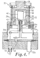
- the coaxial embodiment of the invention is illustrated in greater detail in FIG. 4, with like elements being designated by the same reference numerals used in FIG. 2.
- the enclosure 32 includes a metal base 32a, and a tubular ceramic envelope 32b.
- An inlet tube 32c is provided to introduce xenon gas into the enclosure 32 from an external source (not shown).
- the hollow cathode 36 includes a metal support tube 36a, which retains therein a tubular thermionic cathode insert 36b.
- the insert 36b is preferably made of porous tungsten impregnated with barium aluminate, as in the embodiment of FIGs. 1 and 3.
- a reduced diameter tip 36c which defines a plasma discharge orifice, is fixed to the upper end of the support tube 36a. Further illustrated are generally disc-shaped support members 58 and 60 for fixedly retaining the upper ends of the keeper and control electrode mesh screens 40 and 42 respectively.
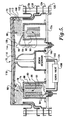
- FIG. 5 illustrates another embodiment of the HOLLOTRON switch which has been scaled to larger size for yet higher current operation.
- the switch of FIG. 5 is designated as 70, and generally has a coaxial or radial configuration as with the switch 30 of FIGs. 2 and 4.
- the switch 70 differs from the switch 30 mainly in the configuration of the hollow cathode, and includes an enclosure 72 having a metal base 72a and an upstanding tubular ceramic insulator 72b.
- a support structure for the hollow cathode includes two upstanding, annular metal walls 74 and 76 which are bent toward each other at their upper ends to define a plasma discharge orifice 78.
- a hollow cathode 80 includes two annular cathode insert sections 82 and 84 retained between the walls 74 and 76, which define an annular hollow space 86 therebetween.
- a heater coil 88 is also shown.
- the insert sections 82 and 84 are preferably made of porous tungsten, impregnated with aluminum carbonate.
- the second alternative is shown on the right side of the figure, and includes a hollow cathode 90 having two annular cathode insert sections 92 and 94, which define an annular space 96 therebetween.
- the insert sections 92 and 94 are preferably made of layered foil rolls of tungsten, with a coating of barium carbonate on the layers of the rolls.
- the hollow cathode 80 is used in applications where rapid startup is not required, but long operating lifetime is a priority.
- the heating coil 88 is optional, and may be omitted depending on the particular design criteria.
- the cathode 90 has a lower thermal capacity than the cathode 80, and provides faster startup than the cathode 80 at the expense of shorter operating lifetime.
- the cathode 90 achieves sufficient self-heating by back ion bombardment to initiate and sustain plasma discharge in a very short time, without an external heater.
- a plasma 98 is discharged axially by the cathode 80 or 90.
- the plasma 98 has an annular shape, and larger cross sectional area, than the linear plasma discharged by the cathodes 18 and 36. This enables substantially increased current as compared to the embodiments of FIGs. 1 to 4.
- the plasma switch 70 further includes a reservoir 100 for containing a supply of xenon gas 102, a conduit 104 for conducting the gas to the interior of the cathode 80 or 90, and a valve 106 for metering the supply of gas.
- the switch 70 further includes an annular keeper electrode 108 in the form of a mesh screen or grid, a control electrode 110 shaped similarly to the electrode 108, and an annular anode 112 disposed coaxially outward of the electrodes 108 and 110.
- the electrodes 108 and 110 are retained at their upper ends by generally disc-shaped support plates 114 and 116 respectively.
- a similar support plate 118 is fixed to the upper end of the anode 112, and may constitute a portion of the enclosure 72.
- a cathode contact 120, anode contact 122, keeper electrode contact 124, and control electrode contact 126 are provided to facilitate connection of the respective elements to external means.
- a cold-starting electrode 128 may be provided to apply an initial starting voltage to the support wall 74.
- the anode 112 may be approximately six inches in diameter.
- the spacing between the anode 112 and control electrode 110 may be approximately 0.5mm, whereas the spacing between the keeper electrode 108 and control electrode 110 may be on the order of 2.0mm.
- Means may be provided to maintain precise orientation and spacing between the anode 112 and electrodes 108 and 110, as well as to compensate for thermal expansion thereof.
- the HOLLOTRON switch concept combines the capacity of a plasma cathode for conducting high current density at low voltage drop, with the current interruption capability obtained using electrode structures in CROSSATRON switches.
- the cylindrical cathode must be raised to thermionic emission temperature to obtain the low-forward voltage drop. Discharges of this type can be maintained at voltages well below the lowest excitation potential for the metastable states of the ambient gas, as shown in studies by R. Forman, "Low-Voltage Arc and Breakdown Effects in Xenon-Filled Thermionic Diodes", J. Appl. Phys., vol. 41, no. 12, pp. 4836-4840, (1970); and R.J.
- the current carrying capacity of the device for a given forward voltage drop depends on the pressure of the ambient gas, the dimensions of the hollow cathode, the emission capability (temperature) of the thermionic emission surface, and the keeper electrode geometry.
- Ion thruster hollow cathodes like the one disclosed in the above referenced patent to Williamson can conduct current densities in excess of A/cm2 through the cathode orifice at low forward voltage drop. In ion thruster cathodes, the gas flows continuously through the hollow cathode region, and current interruption or voltage standoff are not considerations.
- the plasma density must be kept low enough to allow the control grid to extinguish the anode plasma and interrupt the cathode-to-anode current.
- the ambient pressure must be limited to about 1 Torr to avoid Paschen breakdown.
- the hollow cathode may be made of tungsten, or any suitable refractory or high temperature metal capable of thermionic emission.
- the gas may be a noble gas, preferably xenon, or any other gas which is ionizable within the desired parameters.
- the voltage applied to the control electrode need only be on the order of +10 V to close the switch.
- the control electrode voltage may be reduced to the same value as the cathode, or reduced to a negative value on the order of -10 V to open the switch.
- the voltage applied to the keeper electrode will be approximately 50 to 100 V to initiate the plasma discharge, and then be reduced to 10 to 15 V to sustain the discharge.
- the xenon pressure in the vicinity of the cathode may be typically on the order of 50 to 500 mTorr, with the preferred value being approximately 200 mTorr.
- the HOLLOTRON switch is capable of holding off an anode voltage of at least 10 kV, at an average current of 100 A, with a forward voltage drop of less than 20 V, operating at a switching frequency of 20 kHz.
- the switching time is on the order of 300 to 500 ns.
- FIG. 8 illustrates an inverter/converter unit 130 embodying the present invention, including two HOLLOTRON plasma switches 132 and 134 of any of the types described above.
- the unit 130 further includes a fuel cell or other direct current power source 136, for typically producing a DC voltage of 5 kV at a current of 220 A.
- One terminal of the cell 136 is connected to a center tap of a primary winding 138a of a transformer 138.
- the ends of the primary winding 138a are connected through the plasma switches 132 and 134 respectively to the other terminal of the cell 136.
- the transformer 138 is illustrated as having four secondary windings 138b.
- a full wave bridge rectifier 140 is connected across each secondary winding 138b.
- the outputs of the bridge rectifiers 140 are stacked on each other, such that the output voltage across the stack is the sum of the individual output voltages across the secondary windings 138b.
- a periodic square wave signal at typically 20 kHz is applied to the control electrodes of the switches 132 and 134 in out of phase relation, such that one switch will be closed while the other switch is open, and vice-versa. This causes periodic square-wave current flow in the primary winding 138a, which enables an AC square wave voltage to be induced in the secondary windings 138b.
- the turns ratio of the transformer 138 may be selected so that a voltage drop of 10 kV (from the fuel cell 136) across the primary winding 138a will cause 25 kV to be induced in each secondary winding 138b.
- the AC voltage in the secondary windings 138b will be converted to a DC voltage of 25 kV by each bridge rectifier 140, thus producing a DC voltage output across the stack of 100 kV at 10A.
Landscapes
- Plasma Technology (AREA)
- Gas-Filled Discharge Tubes (AREA)
Applications Claiming Priority (2)
| Application Number | Priority Date | Filing Date | Title |
|---|---|---|---|
| US406673 | 1989-09-13 | ||
| US07/406,673 US5075594A (en) | 1989-09-13 | 1989-09-13 | Plasma switch with hollow, thermionic cathode |
Publications (3)
| Publication Number | Publication Date |
|---|---|
| EP0417649A2 true EP0417649A2 (de) | 1991-03-20 |
| EP0417649A3 EP0417649A3 (en) | 1991-08-28 |
| EP0417649B1 EP0417649B1 (de) | 1995-12-27 |
Family
ID=23608990
Family Applications (1)
| Application Number | Title | Priority Date | Filing Date |
|---|---|---|---|
| EP90117209A Expired - Lifetime EP0417649B1 (de) | 1989-09-13 | 1990-09-06 | Plasma-Schalter mit hohler, thermoionischer Kathode |
Country Status (4)
| Country | Link |
|---|---|
| US (1) | US5075594A (de) |
| EP (1) | EP0417649B1 (de) |
| JP (1) | JPH0734350B2 (de) |
| DE (1) | DE69024434T2 (de) |
Cited By (7)
| Publication number | Priority date | Publication date | Assignee | Title |
|---|---|---|---|---|
| EP0506001A1 (de) * | 1991-03-26 | 1992-09-30 | Hughes Aircraft Company | Hohlkathode-Plasmaschalter mit Magnetfeld |
| US5550430A (en) * | 1994-05-16 | 1996-08-27 | Litton Systems, Inc. | Gas discharge closing switch with unitary ceramic housing |
| RU2139590C1 (ru) * | 1997-09-12 | 1999-10-10 | Научно-исследовательский институт энергетического машиностроения Московского технического университета им. Н.Э.Баумана | Катодный узел |
| DE10245392B3 (de) * | 2002-09-28 | 2004-01-08 | Vtd Vakuumtechnik Dresden Gmbh | Rohrförmige Hohlkathode für hohe elektrische Leistungen |
| CN103917034A (zh) * | 2014-03-17 | 2014-07-09 | 上海空间推进研究所 | 一种空心阴极点火电路 |
| EP2243210A4 (de) * | 2008-01-24 | 2015-10-14 | Advanced Fusion Systems Llc | Hochspannungs-umrichter |
| RU183142U1 (ru) * | 2018-06-19 | 2018-09-12 | федеральное государственное бюджетное образовательное учреждение высшего образования "Национальный исследовательский университет "МЭИ" (ФГБОУ ВО "НИУ "МЭИ") | Катодный узел |
Families Citing this family (37)
| Publication number | Priority date | Publication date | Assignee | Title |
|---|---|---|---|---|
| IT1246682B (it) * | 1991-03-04 | 1994-11-24 | Proel Tecnologie Spa | Dispositivo a catodo cavo non riscaldato per la generazione dinamica di plasma |
| JPH0724240B2 (ja) * | 1991-03-05 | 1995-03-15 | 株式会社荏原製作所 | 高速原子線源 |
| US5182496A (en) * | 1992-04-07 | 1993-01-26 | The United States Of America As Represented By The Secretary Of The Navy | Method and apparatus for forming an agile plasma mirror effective as a microwave reflector |
| US5357747A (en) * | 1993-06-25 | 1994-10-25 | The United States Of America As Represented By The Administrator Of The National Aeronautics And Space Administration | Pulsed mode cathode |
| US5451836A (en) * | 1993-07-29 | 1995-09-19 | Litton Systems, Inc. | Thyratron with annular keep-alive electrode |
| JPH07134191A (ja) * | 1993-11-12 | 1995-05-23 | Toshiba Corp | 制御棒駆動機構の駆動装置 |
| IT1269413B (it) | 1994-10-21 | 1997-04-01 | Proel Tecnologie Spa | Sorgente di plasma a radiofrequenza |
| US5835059A (en) * | 1995-09-01 | 1998-11-10 | Lockheed Martin Corporation | Data link and method |
| US6031334A (en) * | 1998-06-17 | 2000-02-29 | Primex Technologies, Inc. | Method and apparatus for selectively distributing power in a thruster system |
| US6829920B1 (en) | 1998-09-14 | 2004-12-14 | The United States Of America As Represented By The Administrator Of The National Aeronautics And Space Administration | Design and manufacturing processes of long-life hollow cathode assemblies |
| US6064156A (en) | 1998-09-14 | 2000-05-16 | The United States Of America As Represented By The Administrator Of Nasa | Process for ignition of gaseous electrical discharge between electrodes of a hollow cathode assembly |
| US6525480B1 (en) * | 1999-06-29 | 2003-02-25 | The Board Of Trustees Of The Leland Stanford Junior University | Low power, linear geometry hall plasma source with an open electron drift |
| US6710524B2 (en) * | 2000-04-11 | 2004-03-23 | Satis Vacuum Industries Vertrieb Ag | Plasma source |
| US6642526B2 (en) * | 2001-06-25 | 2003-11-04 | Ionfinity Llc | Field ionizing elements and applications thereof |
| JP4606434B2 (ja) * | 2001-06-26 | 2011-01-05 | シャープ株式会社 | 表示装置 |
| JP3976589B2 (ja) * | 2001-06-26 | 2007-09-19 | シャープ株式会社 | スイッチング素子およびそれを備える表示装置 |
| US7634042B2 (en) * | 2004-03-24 | 2009-12-15 | Richard Auchterlonie | Pulsed power system including a plasma opening switch |
| RU2304858C1 (ru) * | 2005-11-16 | 2007-08-20 | Федеральное государственное унитарное предприятие "Исследовательский Центр им. М.В. Келдыша" | Катод плазменного ускорителя |
| US7994892B2 (en) * | 2007-06-21 | 2011-08-09 | Jpa Inc. | Oxidative opening switch assembly and methods |
| EP2208404B1 (de) * | 2007-10-16 | 2016-12-07 | Centre National de la Recherche Scientifique (CNRS) | Transientenplasmakugelerzeugungs-system bei grosser distanz |
| US8409459B2 (en) * | 2008-02-28 | 2013-04-02 | Tokyo Electron Limited | Hollow cathode device and method for using the device to control the uniformity of a plasma process |
| US7938707B1 (en) * | 2008-07-07 | 2011-05-10 | Sandia Corporation | Methods for batch fabrication of cold cathode vacuum switch tubes |
| US8541758B1 (en) * | 2011-06-17 | 2013-09-24 | Aqua Treatment Services, Inc. | Ultraviolet reactor |
| US8481966B1 (en) * | 2012-02-28 | 2013-07-09 | Tiza Lab, L.L.C. | Microplasma ion source for focused ion beam applications |
| US8674321B2 (en) * | 2012-02-28 | 2014-03-18 | Tiza Lab, L.L.C. | Microplasma ion source for focused ion beam applications |
| US9484176B2 (en) * | 2012-09-10 | 2016-11-01 | Thomas Schenkel | Advanced penning ion source |
| US20150098259A1 (en) * | 2013-10-08 | 2015-04-09 | General Electric Company | Power converter, method of power conversion, and switching device |
| KR101585889B1 (ko) * | 2014-02-27 | 2016-02-02 | 한국과학기술원 | 고효율 할로우 음극과 이를 적용한 음극 시스템 |
| US10256067B1 (en) | 2018-01-02 | 2019-04-09 | General Electric Company | Low voltage drop, cross-field, gas switch and method of operation |
| US10665402B2 (en) | 2018-02-08 | 2020-05-26 | General Electric Company | High voltage, cross-field, gas switch and method of operation |
| US10403466B1 (en) | 2018-03-23 | 2019-09-03 | General Electric Company | Low sputtering, cross-field, gas switch and method of operation |
| US10418223B1 (en) * | 2018-03-30 | 2019-09-17 | Varian Semiconductor Equipment Associates, Inc. | Foil sheet assemblies for ion implantation |
| CN108551716B (zh) * | 2018-07-06 | 2024-11-19 | 中国科学技术大学 | 一种等离子体生成设备 |
| US10937613B2 (en) * | 2019-02-12 | 2021-03-02 | S&C Electric Company | Triggered gap switching device |
| DE102020128964A1 (de) * | 2020-11-03 | 2022-05-05 | NeutronStar Systems UG (haftungsbeschränkt) | Antriebssystem für Raumfahrzeuge |
| JP2022081824A (ja) | 2020-11-20 | 2022-06-01 | 株式会社東芝 | スイッチ装置 |
| CN114184947B (zh) * | 2021-11-30 | 2024-08-16 | 西北核技术研究所 | 一种等离子体断路开关及脉冲功率负载 |
Family Cites Families (11)
| Publication number | Priority date | Publication date | Assignee | Title |
|---|---|---|---|---|
| US3065372A (en) * | 1949-08-23 | 1962-11-20 | Raytheon Co | Grid controlled gaseous discharge tube |
| US2758253A (en) * | 1953-09-14 | 1956-08-07 | Elmer C Lusk | Glow discharge tube and circuit therefor |
| US3831052A (en) * | 1973-05-25 | 1974-08-20 | Hughes Aircraft Co | Hollow cathode gas discharge device |
| US4297615A (en) * | 1979-03-19 | 1981-10-27 | The Regents Of The University Of California | High current density cathode structure |
| US4301391A (en) * | 1979-04-26 | 1981-11-17 | Hughes Aircraft Company | Dual discharge plasma device |
| US4596945A (en) * | 1984-05-14 | 1986-06-24 | Hughes Aircraft Company | Modulator switch with low voltage control |
| US4645978A (en) * | 1984-06-18 | 1987-02-24 | Hughes Aircraft Company | Radial geometry electron beam controlled switch utilizing wire-ion-plasma electron source |
| US4642522A (en) * | 1984-06-18 | 1987-02-10 | Hughes Aircraft Company | Wire-ion-plasma electron gun employing auxiliary grid |
| US4800281A (en) * | 1984-09-24 | 1989-01-24 | Hughes Aircraft Company | Compact penning-discharge plasma source |
| US4733137A (en) * | 1986-03-14 | 1988-03-22 | Walker Magnetics Group, Inc. | Ion nitriding power supply |
| US4838021A (en) * | 1987-12-11 | 1989-06-13 | Hughes Aircraft Company | Electrostatic ion thruster with improved thrust modulation |
-
1989
- 1989-09-13 US US07/406,673 patent/US5075594A/en not_active Expired - Lifetime
-
1990
- 1990-09-06 EP EP90117209A patent/EP0417649B1/de not_active Expired - Lifetime
- 1990-09-06 DE DE69024434T patent/DE69024434T2/de not_active Expired - Fee Related
- 1990-09-13 JP JP2241351A patent/JPH0734350B2/ja not_active Expired - Lifetime
Cited By (8)
| Publication number | Priority date | Publication date | Assignee | Title |
|---|---|---|---|---|
| EP0506001A1 (de) * | 1991-03-26 | 1992-09-30 | Hughes Aircraft Company | Hohlkathode-Plasmaschalter mit Magnetfeld |
| US5550430A (en) * | 1994-05-16 | 1996-08-27 | Litton Systems, Inc. | Gas discharge closing switch with unitary ceramic housing |
| GB2301933A (en) * | 1994-05-16 | 1996-12-18 | Litton Systems Inc | Gas discharge closing switch |
| RU2139590C1 (ru) * | 1997-09-12 | 1999-10-10 | Научно-исследовательский институт энергетического машиностроения Московского технического университета им. Н.Э.Баумана | Катодный узел |
| DE10245392B3 (de) * | 2002-09-28 | 2004-01-08 | Vtd Vakuumtechnik Dresden Gmbh | Rohrförmige Hohlkathode für hohe elektrische Leistungen |
| EP2243210A4 (de) * | 2008-01-24 | 2015-10-14 | Advanced Fusion Systems Llc | Hochspannungs-umrichter |
| CN103917034A (zh) * | 2014-03-17 | 2014-07-09 | 上海空间推进研究所 | 一种空心阴极点火电路 |
| RU183142U1 (ru) * | 2018-06-19 | 2018-09-12 | федеральное государственное бюджетное образовательное учреждение высшего образования "Национальный исследовательский университет "МЭИ" (ФГБОУ ВО "НИУ "МЭИ") | Катодный узел |
Also Published As
| Publication number | Publication date |
|---|---|
| DE69024434T2 (de) | 1996-05-09 |
| EP0417649B1 (de) | 1995-12-27 |
| EP0417649A3 (en) | 1991-08-28 |
| DE69024434D1 (de) | 1996-02-08 |
| US5075594A (en) | 1991-12-24 |
| JPH03110737A (ja) | 1991-05-10 |
| JPH0734350B2 (ja) | 1995-04-12 |
Similar Documents
| Publication | Publication Date | Title |
|---|---|---|
| US5075594A (en) | Plasma switch with hollow, thermionic cathode | |
| Mesyats et al. | Repetitively pulsed high-current accelerators with transformer charging of forming lines | |
| US5828176A (en) | Planar crossed-field plasma switch and method | |
| EP0386710B1 (de) | Vakuumschalter | |
| US3714510A (en) | Method and apparatus for ignition of crossed field switching device for use in a hvdc circuit breaker | |
| JPH06215700A (ja) | コンパクトな高電流交差電界プラズマスイッチ | |
| US4406952A (en) | Opening switch for interrupting current using a plasma focus device | |
| US5229688A (en) | Method of operating a gas discharge switch and an arrangement for carrying out the method | |
| Gilmour et al. | The interruption of vacuum arcs at high DC voltages | |
| US6049174A (en) | High coulombic switch gas discharge device | |
| US4975924A (en) | Metallic vapor laser apparatus | |
| US3678289A (en) | Magnetic field control circuit for crossed field switching devices | |
| US1790152A (en) | Electrical discharge apparatus | |
| US3699384A (en) | Offswitching of liquid metal arc switching device by internal current diversion to an auxiliary electrode | |
| Kuzmichev | High-voltage pulse generator on the base of plasma tube with cold cathode in crossed fields | |
| EP0416044B1 (de) | Richtungsunabhängiges ignitron mit gerillter kathode | |
| RU2055429C1 (ru) | Устройство для уф-предыонизации в импульсном лазере | |
| JP3441218B2 (ja) | 半導体スイッチ装置とそれを用いた電気装置 | |
| US4611147A (en) | Thermionic gas switch | |
| Gilmour Jr | VACUUM ARC INTERRUPTERS | |
| Hull | Fundamental processes in gaseous tube rectifiers | |
| Caristi et al. | A repetitively operable, high-current interrupter | |
| Kristiansen et al. | High Power Gaseous Opening and Closing Switches | |
| EP0534507A2 (de) | Orientierungsunabhängiges Ignitron mit gerillter Kathode | |
| Cherepenin et al. | Compact low-impedance high-current accelerator |
Legal Events
| Date | Code | Title | Description |
|---|---|---|---|
| PUAI | Public reference made under article 153(3) epc to a published international application that has entered the european phase |
Free format text: ORIGINAL CODE: 0009012 |
|
| AK | Designated contracting states |
Kind code of ref document: A2 Designated state(s): DE FR GB NL |
|
| PUAL | Search report despatched |
Free format text: ORIGINAL CODE: 0009013 |
|
| AK | Designated contracting states |
Kind code of ref document: A3 Designated state(s): DE FR GB NL |
|
| 17P | Request for examination filed |
Effective date: 19910802 |
|
| 17Q | First examination report despatched |
Effective date: 19930901 |
|
| GRAA | (expected) grant |
Free format text: ORIGINAL CODE: 0009210 |
|
| AK | Designated contracting states |
Kind code of ref document: B1 Designated state(s): DE FR GB NL |
|
| REF | Corresponds to: |
Ref document number: 69024434 Country of ref document: DE Date of ref document: 19960208 |
|
| ET | Fr: translation filed | ||
| PLBE | No opposition filed within time limit |
Free format text: ORIGINAL CODE: 0009261 |
|
| STAA | Information on the status of an ep patent application or granted ep patent |
Free format text: STATUS: NO OPPOSITION FILED WITHIN TIME LIMIT |
|
| 26N | No opposition filed | ||
| PGFP | Annual fee paid to national office [announced via postgrant information from national office to epo] |
Ref country code: NL Payment date: 19970821 Year of fee payment: 8 |
|
| REG | Reference to a national code |
Ref country code: GB Ref legal event code: 732E |
|
| PG25 | Lapsed in a contracting state [announced via postgrant information from national office to epo] |
Ref country code: NL Free format text: LAPSE BECAUSE OF NON-PAYMENT OF DUE FEES Effective date: 19990401 |
|
| NLV4 | Nl: lapsed or anulled due to non-payment of the annual fee |
Effective date: 19990401 |
|
| REG | Reference to a national code |
Ref country code: FR Ref legal event code: TP Ref country code: FR Ref legal event code: CD Ref country code: FR Ref legal event code: CA |
|
| REG | Reference to a national code |
Ref country code: GB Ref legal event code: IF02 |
|
| PGFP | Annual fee paid to national office [announced via postgrant information from national office to epo] |
Ref country code: FR Payment date: 20020812 Year of fee payment: 13 |
|
| PGFP | Annual fee paid to national office [announced via postgrant information from national office to epo] |
Ref country code: GB Payment date: 20020815 Year of fee payment: 13 |
|
| PGFP | Annual fee paid to national office [announced via postgrant information from national office to epo] |
Ref country code: DE Payment date: 20020822 Year of fee payment: 13 |
|
| PG25 | Lapsed in a contracting state [announced via postgrant information from national office to epo] |
Ref country code: GB Free format text: LAPSE BECAUSE OF NON-PAYMENT OF DUE FEES Effective date: 20030906 |
|
| PG25 | Lapsed in a contracting state [announced via postgrant information from national office to epo] |
Ref country code: DE Free format text: LAPSE BECAUSE OF NON-PAYMENT OF DUE FEES Effective date: 20040401 |
|
| GBPC | Gb: european patent ceased through non-payment of renewal fee |
Effective date: 20030906 |
|
| PG25 | Lapsed in a contracting state [announced via postgrant information from national office to epo] |
Ref country code: FR Free format text: LAPSE BECAUSE OF NON-PAYMENT OF DUE FEES Effective date: 20040528 |
|
| REG | Reference to a national code |
Ref country code: FR Ref legal event code: ST |