EP0417716A2 - Caméra capable de faire un format fictif - Google Patents
Caméra capable de faire un format fictif Download PDFInfo
- Publication number
- EP0417716A2 EP0417716A2 EP90117453A EP90117453A EP0417716A2 EP 0417716 A2 EP0417716 A2 EP 0417716A2 EP 90117453 A EP90117453 A EP 90117453A EP 90117453 A EP90117453 A EP 90117453A EP 0417716 A2 EP0417716 A2 EP 0417716A2
- Authority
- EP
- European Patent Office
- Prior art keywords
- magnification
- focal length
- taking lens
- directed
- camera
- Prior art date
- Legal status (The legal status is an assumption and is not a legal conclusion. Google has not performed a legal analysis and makes no representation as to the accuracy of the status listed.)
- Withdrawn
Links
Images








Classifications
-
- G—PHYSICS
- G03—PHOTOGRAPHY; CINEMATOGRAPHY; ANALOGOUS TECHNIQUES USING WAVES OTHER THAN OPTICAL WAVES; ELECTROGRAPHY; HOLOGRAPHY
- G03B—APPARATUS OR ARRANGEMENTS FOR TAKING PHOTOGRAPHS OR FOR PROJECTING OR VIEWING THEM; APPARATUS OR ARRANGEMENTS EMPLOYING ANALOGOUS TECHNIQUES USING WAVES OTHER THAN OPTICAL WAVES; ACCESSORIES THEREFOR
- G03B3/00—Focusing arrangements of general interest for cameras, projectors or printers
- G03B3/10—Power-operated focusing
-
- G—PHYSICS
- G03—PHOTOGRAPHY; CINEMATOGRAPHY; ANALOGOUS TECHNIQUES USING WAVES OTHER THAN OPTICAL WAVES; ELECTROGRAPHY; HOLOGRAPHY
- G03B—APPARATUS OR ARRANGEMENTS FOR TAKING PHOTOGRAPHS OR FOR PROJECTING OR VIEWING THEM; APPARATUS OR ARRANGEMENTS EMPLOYING ANALOGOUS TECHNIQUES USING WAVES OTHER THAN OPTICAL WAVES; ACCESSORIES THEREFOR
- G03B13/00—Viewfinders; Focusing aids for cameras; Means for focusing for cameras; Autofocus systems for cameras
- G03B13/02—Viewfinders
- G03B13/10—Viewfinders adjusting viewfinders field
- G03B13/12—Viewfinders adjusting viewfinders field to compensate for change of camera lens or size of picture
-
- G—PHYSICS
- G03—PHOTOGRAPHY; CINEMATOGRAPHY; ANALOGOUS TECHNIQUES USING WAVES OTHER THAN OPTICAL WAVES; ELECTROGRAPHY; HOLOGRAPHY
- G03B—APPARATUS OR ARRANGEMENTS FOR TAKING PHOTOGRAPHS OR FOR PROJECTING OR VIEWING THEM; APPARATUS OR ARRANGEMENTS EMPLOYING ANALOGOUS TECHNIQUES USING WAVES OTHER THAN OPTICAL WAVES; ACCESSORIES THEREFOR
- G03B17/00—Details of cameras or camera bodies; Accessories therefor
- G03B17/18—Signals indicating condition of a camera member or suitability of light
- G03B17/20—Signals indicating condition of a camera member or suitability of light visible in viewfinder
-
- G—PHYSICS
- G03—PHOTOGRAPHY; CINEMATOGRAPHY; ANALOGOUS TECHNIQUES USING WAVES OTHER THAN OPTICAL WAVES; ELECTROGRAPHY; HOLOGRAPHY
- G03B—APPARATUS OR ARRANGEMENTS FOR TAKING PHOTOGRAPHS OR FOR PROJECTING OR VIEWING THEM; APPARATUS OR ARRANGEMENTS EMPLOYING ANALOGOUS TECHNIQUES USING WAVES OTHER THAN OPTICAL WAVES; ACCESSORIES THEREFOR
- G03B7/00—Control of exposure by setting shutters, diaphragms or filters, separately or conjointly
- G03B7/16—Control of exposure by setting shutters, diaphragms or filters, separately or conjointly in accordance with both the intensity of the flash source and the distance of the flash source from the object, e.g. in accordance with the "guide number" of the flash bulb and the focusing of the camera
-
- G—PHYSICS
- G03—PHOTOGRAPHY; CINEMATOGRAPHY; ANALOGOUS TECHNIQUES USING WAVES OTHER THAN OPTICAL WAVES; ELECTROGRAPHY; HOLOGRAPHY
- G03B—APPARATUS OR ARRANGEMENTS FOR TAKING PHOTOGRAPHS OR FOR PROJECTING OR VIEWING THEM; APPARATUS OR ARRANGEMENTS EMPLOYING ANALOGOUS TECHNIQUES USING WAVES OTHER THAN OPTICAL WAVES; ACCESSORIES THEREFOR
- G03B7/00—Control of exposure by setting shutters, diaphragms or filters, separately or conjointly
- G03B7/24—Control of exposure by setting shutters, diaphragms or filters, separately or conjointly automatically in accordance with markings or other means indicating film speed or kind of film on the magazine to be inserted in the camera
-
- G—PHYSICS
- G03—PHOTOGRAPHY; CINEMATOGRAPHY; ANALOGOUS TECHNIQUES USING WAVES OTHER THAN OPTICAL WAVES; ELECTROGRAPHY; HOLOGRAPHY
- G03B—APPARATUS OR ARRANGEMENTS FOR TAKING PHOTOGRAPHS OR FOR PROJECTING OR VIEWING THEM; APPARATUS OR ARRANGEMENTS EMPLOYING ANALOGOUS TECHNIQUES USING WAVES OTHER THAN OPTICAL WAVES; ACCESSORIES THEREFOR
- G03B2217/00—Details of cameras or camera bodies; Accessories therefor
- G03B2217/005—Blur detection
Definitions
- This invention relates to a camera capable of performing real zooming by varying the focal length of a taking lens, and pseudo zooming by varying pseudo print format.
- pseudo telephoto print information such as pseudo magnification is recorded on an exposed film or the like.
- the pseudo print information is used to produce a pseudo telephoto print by enlarging a part of an image on the nagative to a desired view field angle.
- Japanese Unexamined Patent Publication No. 61-295534 discloses a camera in which pseudo print information is written on a near portion of an exposed film frame when photography is executed in a pseudo zooming. During the printing process, a central portion of the negative frame which has been exposed in the pseudo zooming is enlarged in accordance with the written pseudo print information. Consequently, the same print can be obtained as photographed in the real zooming having the same magnification.
- Japanese Unexamined Patent Publication No. 62-135818 discloses a camera capable of performing real zooming and pseudo zooming in which pseudo print information is written on a portion of an exposed film frame which is not to be printed in the printing process.
- Japanese Unexamined Patent Publication No. 63-29821 discloses a camera carrying a program having a plurality of selectable control curves defined by object distances and pseudo magnifications. Only a pseudo magnification is calculated in accordance with a detected object distance and a selected control curve. This camera has only function of performing pseudo zooming. In other words, photography is executed at a fixed real focal length. In the printing process, a central portion of the nagative is enlarged at the calculated pseudo magnification to have a pseudo zoomed image.
- a camera having a zoomable taking lens in which it is carried out based on a detected object distance to calculate such a focal length as to provide a predetermined magnification, and the taking lens is automatically operated to attain the calculated focal length.
- the cameras of Japanese Unexamined Patent Publication Nos. 61-295534 and 62-135818 have the two functions of real zooming and pseudo zooming, However, these camera cannot automatically calculate a proper focal length in accordance with a detected object distance and then automatically adjust the taking lens to have the proper focal length. It is necessary to adjust the taking lens manually. Accordingly, in the case of photograhing a moving object, it is very difficult to attain a proper view field angle soon.
- the camera of Japanese Unexamined Patent Publication No. 63-29821 and the last-mentioned camera can automatically calculate a proper focal length in accordance with a detected object distance and then automatically adjust the taking lens to have the proper focal length.
- these camera cannot perform only one of real zooming and pseudo zooming. Accordingly, these cameras provide smaller magnification ranges than cameras having two functions of real zooming and pseudo zooming.
- a flash light coverage distance which a flash light can reach is comparatively small. Accordingly, only near objects can be photographed in the real zooming by a flash light. Thus, zooming photography cannot fully be carried out.
- a camera of the present invention comprises a taking lens for photographing an object, means for detecting brightness of the object, means for driving the taking lens to change a first magnification representing image size of the object, means for generating a signal of a second magnification irrespective of the first magnification, means for directing an integrated magnification, and means for determining both of the first and second magnifications according to the directed magnification and the detected brightness.
- a camera of the present invention comprises a taking lens for photographing an object, a flash device for illuminating the object, means for detecting that the flash device is used, means for driving the taking lens to change a first magnification representing image size of the object, means for generating a second signal of a second magnification irrespective of the first magnification, means for directing an integrated magnification, and means for determining both of the first and second magnifications according to the directed magnification and detected result of the detecting means.
- a camera of the present invention comprises a taking lens for photographing an object, a viewfinder for showing the object to a photographer, means for driving the taking lens to change a real focal length of the taking lens, means for generating a first signal of a pseudo focal length, means for directing an integrated focal length, means for controlling magnification of the viewfinder according to the directed magnification prior to photographing, and means for determining both of the real and pseudo focal lengths according to the directed magnification after operation of the shifting means.
- a camera of the present invention comprises a taking lens for photographing an object, means for driving the taking lens to change a first magnification of the object, means for generating a first signal of a second magnification irrespective of the first magnification, means for directing an integrated magnification, means for detecting a distance to the object, and means for determining both of the first and the second magnifications according to the detected distance and the directed magnification.
- the camera carries a zooming taking lens 1 having a focal length range of 35 mm to 70 mm. Also, the camera has a pseudo magnification of 2. Accordingly, the camera can provide a greater focal length range of 35 mm to 140 mm by combining a real zooming and a pseudo zooming.
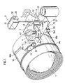
- Fig. 1 shows an arrangement of the taking lens 1, a viewfinder 2, and a flash device 3 of the camera in a perspective view.
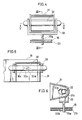
- Fig. 2 shows the arrangement in a plan view.
- the zooming taking lens 1 includes a forward lens member 1a and a rearward lens member 1b.
- the forward lens member 1a and the rearward lens member 1b are movably engaged with a linear guide (not shown) formed in a barrel and slidably engaged with cam grooves 18a, 18b of a cam ring 18, respectively.
- Teeth 18a are formed on a peripheral portion of the cam ring 18.
- the teeth 18c is meshed with a gear 21 which is in turn meshed with a gear 19 of a zoom lens motor 14 (hereinafter referred to as ZL-motor). Accordingly, the rotational force of the ZL-motor 14 is transmitted to the cam ring 18 through the gears 19, 21 and the teeth 18c to rotate the cam ring 18.
- the forward and rearward lens members 1a, 1b are respectively pused by the cam grooves 18a, 18b according to the rotation of the cam ring 18 to move on an optical axis L1 (see Fig. 2) along the linear guide at different speeds.
- the focal length of the taking lens 1 is changed.
- a viewfinder 2 is a zoom finder having an objective lens 4 including a forward member 41 and a rearward member 42. Support members 41a, 42a of the forward and rearward members 41, 42 are slidably engaged with the cam grooves 16a, 16b formed in a cam plate 16 and movably engaged with a linear guide groove (not shown) of a linear guide plate 23 (see Fig. 4) provided under the cam plate 16, respectively.
- a rack 16d is formed in a forward end of the cam plate 16.
- a gear 20 of a viewfinder motor 15 (hereinafter referred to as F-motor) is engaged with the rack 16d.
- F-motor a viewfinder motor 15
- the cam plate 16 is horizontally moved perpendicularly to an optical axis L2 (see Fig. 2).
- the forward and rearward members 41, 42 are respectively pushed by the cam grooves 16a, 16b to move on the optical axis L2 at different speeds along the linear guide groove.
- the focal length of the objective lens 4 is changed.
- the optical axis L1 of the taking lens 1 is parallel with the optical axis L2 of the objective lens 4.
- the focal length range of the objective lens 4 is greater than that of the taking lens 1.
- the viewfinder 2 includes an eye-piece lens 5, condensor lens 6, a Porro mirror system of mirrors 7 to 10, a finder field unit 11, and a photocell 12 provided below the mirror 8.
- the photocell 12 is disposed at a position which is apart away from the mirror 8 at the same distance as the finder field unit 11.
- the photocell 12 has a light reception surface made of a ultraviolet ray reflection film. A filter for shutting off ultraviolet rays is omitted to simplify the construction.
- the finder field unit 11 includes an electro-optical device such as LCD or ECD.
- a masking portion 11 is porvided in a peripheral portion of the finder field unit 11.
- an indication of real zooming or pseudo zooming and an indication of a focal length calculated in a program zooming, as described below.
- the inverted image formed on the finder field unit 11 is turned to an erect image by the mirrors 9, 10 to introduce to the eye-piece lens 5.
- a photographer can view the image of the object surrounded by the masking portion 11a through the eye-piece lens 5.
- the mirror 8 is made of a partial transparent mirror, a partial half-transparent mirror, or an entire half-transparent mirror.
- the partial transparent mirror has a transparent portion or a hole formed at a center portion of the reflecting surface.
- the partial half-transparent mirror has a half-transparent portion at a center portion of the reflecting surface.
- the entire half-transparent mirror is half transparent in the entire surface.
- the mirror 8 causes a part of the light transmitted through the objective lens 4 to be incident upon the photocell 12.
- a signal produced by the photocell 12 is used for an exposure calculation, and also used for controlling flash light in the flash photography.
- the mirror 7 is made of a half-transparent mirror and the photocell 12 is disposed at a position which is apart away from the mirror 7 at the same distance as the finder field unit 11.
- the photocell 12 is provided in the viewfinder 12 in this embodiment, it may be appropriate to provide the photocell 12 in the camera body to receive light transmitted through the taking lens 1.
- a xenon lamp 32 of a flash device 3 is movable in forward and rearward directions which are parallel with the optical axis L1 in accordance with the horizontal movement of the cam plate 16.
- Fig. 4 is a front view of the flash device 3.
- Fig. 5 is a cross sectional view taken along the line V-V in Fig. 4.
- Fig. 6 is a cross sectional view taken along the line VI-VI in Fig. 4.
- a support member 33a of a holder 33 in the flash device 3 is slidably engaged with the cam groove 16c provided in the cam plate 16 and movably engaged with a linear guide groove 23a of the linear guide plate 23 (see Fig. 4).
- the cam plate 16 is moved horizontally, the support member 33a is pushed by the cam groove 16c to move the holder 33 in the forward and rearward directions.
- a reflecting shade 31 is fixed on the camera body A.
- the xenon lamp 32 held on the holder 33 is moved along a guide groove 31a formed in the sides of the reflecting shade 31.
- the guide groove 31a is parallel with the optical axis L1. Accordingly, a relative position between the xenon lamp 32 and a reflecting surface of the reflecting shade 31 is changed.
- the illuminating angle of the flash device 3 becomes narrow, in other words, the flash light coverage range of the flash device 3 becomes far.
- the illuminating angle of the flash device 3 becomes wide, in other words, the flash light coverage range of the flash device 3 becomes near.
- the cam plate 16 When the zoom switch is actuated to drive the F-motor 15 in the clockwise direction, the cam plate 16 is moved away from the taking lens 1, and the forward and rearward members 4a, 4b of the objective lens 4 of the viewfinder 2 are moved in the forward direction along the linear guide with decreasing the distance between them, in other words, with the focal length of the objective lens 4 increasing. Consequently, the image magnification of the viewfinder 2 increases.
- the holder 33 of the flash device 3 moves in the rearward direction along the linear guide 23a in accordance with the movement of the plate 16. Consequently, the relative distance between the xenon lamp 32 and the reflecting surface 31b decreases, and the illuminating angle of the flash device 3 becomes narrow.
- the F-motor 15 is driven in the counterclockwise direction, the cam plate 16 is moved toward the taking lens 1, and movements of the forward and rearward members 4a, 4b of the objective lens 4 and the holder 33 of the flash device 3 are reversed respectively. Consequently, the magnification of the viewfinder decreases, and the illuminating angle of the flash device 3 becomes wide.
- the illuminating angle of the flash device 3 is changed in synchronization with the movement of the objective lens 4, but it is permittable to change the illuminating angle of the flash device 3 in synchronization with the movement of the taking lens 1.
- the film container 17 has a microcomputer carrying a memory. Pseudo telephoto print information such as pseudo magnification can be recorded in the memory.
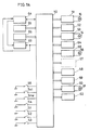
- FIG. 7A showing a circuit construction of the camera
- indicated at 50 is a central control unit (CPU) for performing a centralized control of drivings of actuators to be described, and operation sequences and exposure calculation.
- Indicated at 51 is a F-motor control circuit for controlling the rotational direction and driving amount of the F-motor 15 by use of command signal.
- Indicated at 52 is an encoder for detecting the focal length of the viewfinder 2.
- Indicated at 53 is a ZL-motor control circuit for controlling the rotational direction and driving amount of the ZL-motor 14 by use of command signal.
- Indicated at 54 is an encoder for detecting the focal langth of the taking lens 1.
- Indicated at 55 is a film control circuit for controlling a film motor 56 for advancing the film 22 every frame.
- Indicated at 57 is the microcomputer carried by the film container 17.
- Indicated at 58 is a film sensitivity read circuit for reading a film sensitivity indicated in the form of codes on the film container 17.
- Indicated at 59 is a display circuit for displaying a focal length set by the real or pseudo zooming, or a focal langth calculated in an autoprogram mode to be described below.
- Indicated at 60 is a focusing control circuit for controlling a focusing lens motor 61.
- the focusing lens motor 61 is adopted for driving a focusing lens (not shown) of the taking lens 1.
- a shutter control circuit for controlling the opening and closing of the shutter.
- the shutter used in this embodiment serves as a diaphragm.
- an aperture value is automatically determined. Relationship between shutter speeds and aperture values is shown in Fig. 8.
- a control curve A represents a case in which the focal length of the taking lens 1 is 35 mm.
- a curve B represents a case in which the focal length of the taking lens 1 is 70 mm.
- a control curve C represents a case in which the focal length of the taking lens 1 is any one of 35 mm to 70 mm.
- the control curves A, B, C In a region in which the shutter speed changes with the aperture value, that is, in a region in which the shutter speed is greater than 1/30 second), the control curves A, B, C have the same inclination.
- Indicated at 63 is a flash unit having a zoom flash device 3.
- the illumination timing of the flash device 3 is controlled by the CPU 50.
- Indicated at 64 is a dimmer circuit.
- the photocell 12 receives reflected flash light from the object.
- the dimmer circuit 64 integrates the reflected light, and generates a stop signal to the flash unit 63 to stop the illumination of flash light when a predetermined exposure is obtained.
- Indicated at 65 is a light measurement circuit for measuring the brightness of the object based on natural light received by the photocell 12.
- Indicated at 66 is a distance measurement circuit for detecting the distance to the subject.
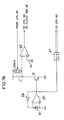
- the dimmer circuit 64 and the light measurement circuit 65 have a common input portion.
- the input portion includes the photocell 12, an operation amplifier OP, a logarithmic compression diode Dp provided between the (-) input terminal and the output terminal of the operation amplifier OP.
- the light measurement circuit 65 consists of the input portion and an A/D converter 67, and sends the converted output to the CPU 50.
- the dimmer circuit 64 includes a transistor Q for expanding a logarithmicly compressed output, a condensor C for charging the expanded output, a switch SW1n for allowing the condensor C to start the charging of the output when the flash light illumination is stopped, and a comparator 68 for comparing the voltage of the condensor C with a reference voltage Vr, and sending a charge complete signal to the CPU 50 when the voltage of the condensor C reaches the reference voltage Vr.
- the flash unit 63 stops the illumination of flash light when the stop signal is input.
- the reference voltage Vr is changed in accordance with control shutter speed Tvc sent from the CPU 50. This is becuase of the fact that this embodiment has a lens shutter, accordingly, it is required to compensate for variation of the amount of flash light incident on a film surface per unit time in accordance with variation of the aperture area of the lens shutter. Specifically, as the control shutter speed Tvc rises (the aperture area decreases), the amount of flash light incident on the film surface per unit time decreases. Accordingly, when the control shutter speed Tvc increases, the reference voltage Vr is raised so that the stop signal is generated at a delayed time to compensate for a decrease in the amount of flash light incident on the film surface per unit time. The reference voltage Vr is changed in accordance with the sensitivity Sv of a loaded film.
- a photography ready switch 51 is turned on when a release button is pressed halfway.
- the switch S1 is turned on, the light and distance measurement for photography is performed.
- a release switch S2 is turned on when the release button is pressed all the way.
- the switch S2 is turned on, the exposure is started.
- a zooming mode change-over switch S3 is adopted for changing an autoprogram zooming mode to a power zooming mode and vice versa.
- APZ autoprogram zooming mode
- it is automatically performed to determine the focal length to assure a predetermined magnification according to the distance to the object which is detected by the distance measurement circuit 66.
- PZ power zooming mode
- a desired focal length is manually set.
- a zooming reset switch S4 is turned on when the taking lens 1 is placed in an initial position, in this embodiment, the focal length of 35 mm.
- the taking lens 1 is always returned to the initial position. Owing to the fact that the switch S4 is turned on, the initial position return of the taking lens 1 is detected.
- a switch S5 is actuated by the photographer to forcibly prohibit the illumination of flash light.
- the switch S5 is turned on, the illumination is prohibited.
- Switches Szt and Szw are actuated by the photographer in the PZ mode to direct the driving direction of the taking lens 1.
- the taking lens 1 is driven to the teleward limit when the switch Szt is turned on.
- the taking lens 1 is driven to the wideward limit when the switch Szw is turned on.
- the camera has the real zooming and pseudo zooming.
- the APZ mode is available in the entire, range of the real zooming and pseudo zooming.
- the taking lens 1 is a zoom lens whose focal length is variable from 35 mm to 70 mm.
- the magnification of the pseudo zooming is two. Accordingly, the camera can perform zooming from 35 mm to 140 mm.
- the focal length is set at 105 mm (i.e., a zooming ratio of 3)
- photography is executed at a focal length of 70 mm (i.e., a zooming ratio of 2) and the pseudo magnification is set at 1.5.
- the pseudo magnification of 1.5 is recorded in the memory carried by the film container 17.
- the pseudo magnification is read out in the printing process, a part of the negative, usually a center portion of the negative, is enlarged to the magnification of 1.5 and then printed. Consequently, the photograph can be obtained which is identical to one obtained by a taking lens having a real focal length of 105 mm (i.e., a zooming ratio of 3).
- a program zooming is performed from a focal length of 35 mm to 140 mm by use of the real zooming and the pseudo zooming.
- a necessary focal length is calculated from a detected distance to the object. If the necessary focal length is 105 mm, the focal length of the viewfinder 2 is set at 105 mm and the photographer can see an image at a field angle corresponding to the focal length of 105 mm through the viewfinder 2.
- the focal length of the taking lens 1 is set at the maximum of 70 mm and the pseudo magnification is set at 1.5. In printing process, consequently, the photograph can be obtained which is identical to one obtained by a taking lens having a real focal length of 105 mm.
- the performing of the pseudo zooming is not limited to the focal length range exceeding the real focal length of the taking lens 1. Only the pseudo zooming may be performed. The pseudo zooming may be performed in the real focal length range. Further, depending on the brightness of the subject and the distance to the subject, the real zooming and the pseudo zooming may be selectably used to obtain a desired focal length.
- the APZ is executable for subjects within subject distances of 1 m to 3 m.
- the APZ is executable for subjects within subject distances of 1 m to 5 m. Accordingly, it will be seen that the use of the real zooming and the pseudo zooming for a camera having a small photographic magnification extends the APZ executable focal length range.
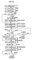
- Fig. 9 shows a main routine.
- Step #5 it is discriminated whether the switch S1 is turned on. If the switch S1 is turned on, this main routine proceeds to Step #10(#70) in which a first subroutine is executed, and then returns to Step #5.
- Step #15 it is discriminated whether the APZ mode is selected depending on whether the switch S3 is turned on. If the APZ mode is selected, this main routine returns to Step #5.
- Step #20 it is discriminated whether the switch Szw is turned on, that is, the objective lens 4 of the viewfinder 2 is moved to the wideward limit. If the switch Szw is turned on, this main routine proceeds to Step #25 in which the end focal length Z is set at 35 mm, and proceeds to Step #40 (#160) in which a second subroutine is executed, and then returns to Step #5.
- Step #30 it is discriminated whether the switch Szt is turned on, that is, the objective lens 4 of the viewfinder 2 is moved to the teleward limit. If the switch Szt is turned on, this main routine proceeds to Step #35 in which the end focal length Z is set at 140 mm, and proceeds to Step #40 (#160), and then returns to Step #5.
- Step #45 it is discriminated whether the F-motor 15 is driven depending on whether a flag ZFMUF is set at 1. If the F-motor 15 is driven, that is the flag ZFMUF is set at 1, this main routine proceeds to Step #50 in which the F-motor is braked for 10 seconds, proceeding to Step #55 in which the supply to the F-motor 15 is turned off, proceeding to Step #60 in which the flag ZFMUF is set at 0, then returning to Step #5. If the F-motor 15 is not driven, that is the flag ZFMUF is not set at 1, this main routine returns to Step #5.
- the first subroutine will be described with reference to Fig. 10.
- the brightness of the subject is measured to calculate the exposure control value.
- the magnification for the real zooming and the magnification for the pseudo zooming are calculated from a detected distance to the subject.
- the taking lens 1 is driven to a focal length corresponding to the real zooming magnification and focused to the subject, and the exposure is finally performed based on the calculated exposure control value.
- Step #90(#160) the second subroutine is executed to set the viewfinder 2 at such a focal length as to attain the end focal length Z.
- Step #80 If the APZ mode is not selected in Step #80, that is, the PZ mode is selected, this subroutine proceeds directly to Step #95(#250).
- Step #95(#250) a third subroutine is executed to calculate the real zooming magnification OZ, the pseudo zooming magnification EZ, and the control shutter speed Tvc. Thereafter, this subroutine proceeds to Step #100(#500) in which a fourth subroutine is executed to display the real zooming magnification OZ or the pseudo zooming magnification EZ in the viewfinder 2, or in the display portion in the top surface of the camera.
- the real zooming magnification OZ and the pseudo zooming magnification EZ have values of 0 to 1 respectively.
- a real zooming magnification OZ of 0 means that the zooming ratio of the taking lens 1 is 1, that is, the focal length of the taking lens 1 is 35 mm.
- a real zooming magnification OZ of 1 means that the zooming ratio of the taking lens 1 is 2, that is, the focal length of the taking lens 1 is 70 mm.
- a pseudo zooming magnification EZ of 0 means that the pseudo magnification is 1, that is, the entire of the negative is printed.
- a pseudo zooming magnification EZ of 1 means that the pseudo magnification is 2, that is, a 1/4 portion of the negative is enlarged two times in the printing process.
- Step #105 it is discriminated whether the switch S2 is turned on. If the switch S2 is turned off, this subroutine proceeds to Step #145 in which it is discriminated whether the switch S1 is turned on. If the switch S1 is turned on, this subroutine returns to Step #105. If the switch S1 is not turned on, this subroutine returns to the main routine.
- Step #110 it is discriminated whether the real zooming magnification OZ is 0. If the real zooming magnification OZ is not 0, this subroutine proceeds to Step #115 (#550) in which a fifth subroutine is executed to set the taking lens 1 at such a focal length as to attain the real zooming magnification OZ. If the real zooming magnification OZ is 0, this subroutine proceeds directly to Step #120(#600). In other words, the focal length of the taking lens 1 is held at the initial position of 35 mm.
- Step #120(#600) a sixth subroutine is executed to expose the film at the calculated exposure control value. Thereafter, this subroutine proceeds to Step #125 in which the pseudo zooming magnification EZ is recorded in the memory 57, proceeding to Step #130(#550) in which a seventh subroutine is executed to drive the taking lens 1 to the initial position, and proceeding to Step #135 in which the film is advanced one frame. Thereafter, this subroutine proceeds to Step #140 in which discrimination as to whether the switch S1 is turned on is repeated until the switch S1 is turned off. When the switch S1 is turned off, this subroutine returns to the main routine.
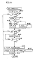
- the second subroutine will be described with reference to Fig. 11.
- the objective lens 4 of the viewfinder 2 is moved in a directed direction.
- the viewfinder 2 is automatically set at such a focal length as to attain the end focal length Z calculated from the subject distance Dv.
- Step #160 first, the present focal length FZ is detected by the encoder 26. Thereafter, this subroutine proceeds to Step #165 in which it is discriminated whether the present focal length FZ is equal to the end focal length Z calculated in Steps #25, #35, or Step #85.
- this subroutine returns to Step #5 of the main routine, or Step #95 of the first subroutine. Specifically, when executed in Step #40 of the main routine, i.e., in the PZ mode, this subroutine returns to Step #5 of the main routine. When executed in Step #90 of the first subroutine, i.e, in the APZ mode, this subroutine returns to Step #95 of the first subroutine.
- Step #170 the flag ZFMUF is set at 1
- Step #175 it is discriminated whether the present focal length FZ is smaller than the end focal length Z.
- Step #180 If the present focal length FZ is smaller than the end focal length Z, this subroutine proceeds to Step #180 in which it is started driving of the objective lens 4 of the viewfinder 2 to the teleward limit, and proceeds to Step #190. If the present focal length FZ is greater than the end focal length Z, this subroutine proceeds to Step #185 in which it is started driving of the objective lens 4 of the viewfinder 2 to the wideward limit, and proceeds to Step #190.
- Step #190 it is discriminated whether the APZ mode is selected. If the APZ mode is not selected, that is, the PZ mode is selected, this subroutine returns to Step #5 of the main routine. If the APZ mode is selected, this subroutine proceeds to Step #195 in which the present focal length FZ is detected, and proceeds to Step #200 in which it is discriminated whether the present focal length FZ is equal to the end focal length Z. This discrimination is repeated until the present focal length FZ is equal to the end focal length Z.
- Step #205 in which the F-motor is braked for 10 seconds, proceeding to Step #210 in which the supply to the F-motor 15 is turned off, proceeding to Step #215 in which the flag ZFMUF is set at 0, then returns to Step #95 of the first subroutine.
- the third subroutine will be described with reference to Figs. 12A and 12B.
- this subroutine depending on the subject distance and the subject brightness, either natural light photography mode or flash light photography mode is selected. It is executed to calculate an exposure control value for each of the natural light photography mode and the flash light photography mode, a real zooming magnification OZ, a pseudo zooming magnification EZ.
- a real zooming magnification OZ a real zooming magnification OZ
- a pseudo zooming magnification EZ a pseudo zooming magnification EZ.
- one of the real zooming and the pseudo zooming is given priority. When the subject is bright, the real zooming is given priority. When the subject is dark and flash light is emitted, the pseudo zooming is given priority. Further, when the subject is dark but flash light is prohibited, the real zooming and the pseudo zooming are combined in accordance with the exposure control value.
- the focal length FZ is detected by the encoder 26 in Step #280. The focal length FZ is set manually, or automatically in the APZ mode.
- Step #285 based on the focal length FZ, a shutter speed Tvf for preventing the influence of camera shake is calculated. The shutter speed Tvf is obtained by converting the value of 1/FZ to an Apex value.
- this subroutine proceeds to Step #290 in which it is discriminated whether the focal length FZ is smaller than or equal to 70 mm. If the focal length FZ is greater than 70 mm, this subroutine proceeds to Step #295 in which the exposure correction value ⁇ Ev is set at 1. If the focal length FZ is smaller than or equal to 70 mm, this subroutine proceeds to Step #300 in which the exposure correction value ⁇ Ev is set in accordance with the focal length FZ.
- the exposure correction value ⁇ Ev is stored in a memory of the CPU 50 in advance.
- Fig. 17 represented at A is a control curve for the focal length of 35 mm, which is a reference focal length in this embodiment.
- Represented at C is a control curve for an arbitrary focal length.
- Avo′ are respectively aperture values for the control curves A, C.
- the aperture value varies as the focal length of the taking lens 1 varies. This variation is represented at ⁇ Avo.
- the shutter speed is found out to be Tv in accordance with the control curve A. If the taking lens 1 is set to the focal length of the control curve 6, the shutter speed is necessary to set at Tvc.
- the shutter speed is calculated in accordance with the reference control curve A. Accordingly, it is necessary to correct the exposure value Ev in accordance with the variation of focal length to assure an appropriate exposure. Assuming that a corrected exposure value is Ev′, as shown in Fig. 17, an intersection point of the reference control curve A and the corrected exposure value Ev′ has the shutter speed of Tvc. In Steps #295, #300, the exposure correction value ⁇ Ev is determined. The reason why the exposure correction value is set at 1 when the focal length FZ is greater than 70 mm is that the focal length of the taking lens 1 is set at 70 mm, and an exceeding magnification is accomplished by the pseudo zooming. As shown in Fig. 17, the exposure correction value ⁇ Ev is equal to the aperture value variation ⁇ Avo.
- the aperture value variation ⁇ Avo may be calculated based on the f-number of the objective lens.
- the focal length range of 35 mm to 70 mm the real zooming is performed and the focal length of the taking lens 1 is used as the present focal length FZ, in the focal length range greater than 70 mm, the pseudo zooming is further performed.
- the reason why the real zooming is given priority in the focal length ragne of 30 mm to 70 mm is that enlargement of a negative image inevitably lowers the quality of a printed picture.
- Step #305 the corrected exposure value Ev′ is calculated by subtracting the exposure correction value ⁇ Ev from the exposure value calculated in Step #275. Subsequently, in Step #310, the shutter speed Tv is calculated from the corrected exposure value Ev′.
- zooming ratio data Fz ⁇ is calculated based on the present focal length FZ.
- the zooming ratio data Fz ⁇ has the same functional meaning as the real zooming magnification OZ and the pseudo zooming magnification EZ.
- the zooming ratio data Fz ⁇ is settable at 0 to 2 depending on the focal length FZ. For example, if the focal length FZ is 35 mm, the zooming ratio data Fz ⁇ is set at 0. If the focal length FZ is 70 mm, the zooming ratio data Fz ⁇ is set at 1. If the focal length FZ is 140 mm, the zooming ratio data Fz ⁇ is set at 2.
- Step #320 it is discriminated whether the shutter speed Tv is smaller than the shake prevention shutter speed Tvf. If the shutter speed Tv is not smaller than the shake prevention shutter speed Tvf, this subroutine proceeds to Step #325 in which it is discriminated whether the focal length FZ is smaller than or equal to 70 mm. If the focal length FZ is smaller than or equal to 70 mm, this subroutine proceeds to Step #330 in which the zooming ratio data Fz ⁇ is used as the real zooming magnification OZ to cause only the real zooming to perform, and proceeds to Step #390.
- the shutter speed Tv is set as the control shutter speed Tvc. Thereafter, this subroutine returns to Step #100 of the first subroutine.
- Step #345 it is discriminated whether the flash light prohibition mode is selected depending on whether the switch 55 is turned on, or the flash condensor is charged. If the flash light prohibition mode is not selected, this subroutine proceeds to Step #350 in which the flag FLF is set at 1 to permit the flash light emission, and proceeds to Step #355 in which it is discriminated whether the focal length FZ is smaller than or equal to 70 mm.
- this subroutine proceeds to Step #360 in which the zooming ratio data Fz ⁇ is used as the pseudo zooming magnification EZ to cause only the pseudo zooming to perform, and proceeds to Step #380 in which the exposure correction value ⁇ Ev is added to the corrected exposure value Ev′ calculated in Step #305 to obtain the exposure value Ev calculated in Step #275. This is because of the fact that even if the focal length FZ is smaller than 70 mm, the real zooming is not performed.
- this subroutine proceeds to Step #385 in which the shutter speed Tv is calculated based on the exposure value Ev, and proceeds to Step #390 in which the shutter speed Tv is set as the control shutter speed Tvc, and returns to Step #100 of the first subroutine.
- OZ Fz ⁇ - 1.
- This causes the pseudo zooming magnification to set at the maximum magnification of 2, and cause the real zooming to perform to attain the remaining magnification, and proceeds to Step #375 in which the exposure correction value ⁇ Ev is calculated from the real zooming magnification OZ, and proceeds to Step #380.
- the pseudo zooming is given priority in order to make the focal length of the taking lens 1 as short as possible, and decrease the aperture value Av (i.e., increase the opening diameter of the aperture diaphragm) to increase the flash light coverage range.
- the flash light coverage range is 3.8 m
- the focal length is 70 mm
- the flash light coverage range is 2.7 m.
- the flash light coverage range is expanded 1.4 times owing to the fact that the priority is given to the pseudo zooming.
- the priority is given to the real zooming.
- the control shutter speed Tvc is determined based on the natural light. Accordingly, there is a likelihood that the emission of flash light causes over exposure. Also, there is a likelihood that if the object is dark, the control shutter speed Tvc is under the shake prevention shutter speed Tvf. However, these likelihoods are not important as mentioned below.
- the effect of the pseudo zooming is not obtainable until printing is executed. Accordingly, it is usual to use a negative film.
- the negative film have a wide latitude, particularly wide in the over or bright side. Also, it is possible to correct the exposure when a print is made from the negative. Accordingly, it will be seen that the over-exposure is not important or problem. On the contrary, the over-exposure can improve the granularity of the film. It can be said that a reasonable over-exposure may be desirable for the camera capable of providing a pseudo print format.
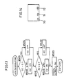
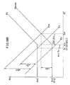
- the limit shutter speed Ktv is a limit value beyond which the aperture value and the shutter speed can be controlled together, i.e., the shutter speed in the bending point of the control curve. As shown in Fig. 8, the limit shutter speed Ktv of this embodiment is 1/30 second (the APEX value is 5).
- Fig. 18A shows a case in which the shutter speed Tv is greater than or equal to the limit shutter speed Ktv, and the difference ⁇ Evf is smaller than or equal to ⁇ Ev.
- Fig. 18B shows another case in which the shutter speed Tv is smaller than the limit shutter speed Ktv, and the difference ⁇ Evf is greater than ⁇ Ev., 18B.
- Represented at Ev is the exposure value calculated in Step #305.
- Represented at Ev′ is the corrected exposure value in Step #305.
- the minimum focal length of the camera is 35 mm.
- ⁇ Av (Tvf - Tv)
- Step #410 it is discriminated whether the exposure difference ⁇ Evf is greater than the exposure correction value ⁇ Ev. If the exposure difference ⁇ Evf is greater than the exposure correction vague ⁇ Ev, i.e., the influence of camera shake is received even if the priority is given to the pseudo zooming, this subroutine proceeds to Steps #355 to #390 in which the magnifications OZ, EZ are set with the priority being given to the pseudo zooming, and the control shutter speed Tvc is calculated, as described above. Consequently, the object can be properly exposed while preventing the influence of camera shake as much as possible.
- Step #415 the focal length FZ is smaller than or equal to 70 mm. If the focal length FZ is smaller than or equal to 70 mm, this subroutine proceeds to Step #420 in which a zooming ratio correction data ⁇ Fz ⁇ is calculated based on the exposure difference ⁇ Evf.
- the zooming ratio correction data ⁇ Fz ⁇ is stored in a memory of the CPU 50, the exposure difference ⁇ Evf is read out as an address.
- this subroutine proceeds to Step #425 in which the difference between the zooming ratio data Fz ⁇ and the zooming ratio correction data ⁇ FZ ⁇ is set as the real zooming magnification data OZ, and proceeds to Step #430 in which the zooming ratio correction data ⁇ FZ ⁇ is set as the pseudo zooming magnification EZ, and proceeds to Step #435 in which the shake prevention shutter speed Tvf is set as the shutter speed Tv, and proceeds to Step #465 in which the shutter speed Tv is set as the control shutter speed Tvc, and returns to Step #100 of the first subroutine.
- the zooming ratio data of (Fz ⁇ - ⁇ Fz ⁇ ) used in Step #425 corresponds to the focal length FZ′ shown in Fig. 18A.
- this subroutine proceeds to #460 in which the shutter speed Tv is calculated based on the exposure value Ev, and proceeds to Step #465 in which the shutter speed Tv is set as the control shutter speed Tvc, and returns to Step #100 of the first subroutine.
- the zooming ratio data and the control shutter speed Tvc are calculated with the priority being given to the pseudo zooming, when the exposure difference ⁇ Evf is equal to or smaller than the exposure correction value ⁇ Ev, and the focal length FZ is greater than 70 mm.
- the exposure difference ⁇ Evf is equal to or smaller than the exposure correction value ⁇ Ev
- the object can be properly exposed without receiving the influence of camera shake by increasing the use of the pseudo zooming.
- the focal length FZ′ of the taking lens to assure proper exposure at the shutter speed Tvf is 50 mm (see Fig. 18A)
- photography is executed at a focal length FZ smaller than or equal to 100 mm, it is possible to obtain proper exposure without receiving the influence of camera shake by setting the focal length of the taking lens at 50 mm and compensating for the deficient magnification by the pseudo zooming.
- the focal length FZ is greater than 100 mm, the maximum magnification of the pseudo zooming is 2.
- the focal length of the taking lens must be greater than 50 mm for the real zooming.
- the focal length FZ is 120 mm
- the focal length of the taking lens 1 must be equal to or greater than 60 mm.
- the influence of camera shake is likely to be received to assure proper exposure. Accordingly, even if the exposure difference ⁇ Evf is equal to or smaller than the exposure correction value ⁇ Ev, when the focal length FZ is greater than 70 mm, the zooming ratio data and the control shutter speed Tvc are calculated with the priority being given to the pseudo zooming.
- the zooming control and the exposure control are identical to the case that the exposure difference ⁇ Evf is equal to or smaller than the exposure correction value ⁇ Ev, and the focal length FZ is greater than 70 mm, except for the discrimination as to whether flash light is emitted. Accoridingly, this leads a simplified software preparation, a reduced number of parts, and a smaller size of memory.
- Step #415 it is discriminated whether the exposure difference ⁇ Evf is equal to or smaller than the exposure correction value ⁇ Ev.
- the focal length FZI is calculated based on the exposure difference ⁇ Evf, and it is discriminated whether the focal length FZ is greater than 2FZ′ which is the product of the FZ′ and the maximum pseudo zooming magnification of 2. If the focal length FZ is equal to or smaller than 2FZ′, the subroutine proceeds to Step #420 and subsegent steps. If the focal length FZ is greater than 2FZ′, the subroutine proceeds to Step #440 and subsequent steps. Consequently, it will be seen that when the flash light photography is not required, photographs of improved quality can be obtained by giving the priority to the pseudo zooming as much as possible, and thus preventing the influence of camera shake.
- a representation 70 means that the pseudo zooming is being performed.
- a representation 71 means that the real zooming is being performed.
- a set focal length is displayed in a representation portion 72.
- Step #500 it is discriminated whether the real zooming magnification OZ set in the third subroutine is equal to 0. If the real zooming magnification OZ is equal to 0, this subroutine proceeds to Step #505 in which the representation OZ is lighted off, and proceeds to Step #515. If the real zooming magnification OZ is not equal to 0, this subroutine proceeds to Step #510 in which the representation OZ is lighted on, and proceeds to Step #515 in which it is discriminated whether the pseudo zooming magnification EZ is equal to 0. If the pseudo zooming magnification EZ is equal to 0, this subroutine proceeds to Step #520 in which the representation EZ is lighted off, and proceeds to Step #530.
- Step #525 in which the representation EZ is lighted on, and proceeds to Step #530 in which a set focal length is displayed in the representation portion 72, and return to Step #105 of the first subroutine.
- a display portion such as an LCD panel may be provided in an outside surface of the camera, e.g., a top surface, to display the representations OZ, EZ, the focal length and the like.
- the fifth subroutine will be described with reference to Fig. 15.
- the ZL-motor 14 is driven based on the real zooming magnification OZ and the taking lens 1 is set at a predetermined focal length.
- Step #550 it is discriminated whether the flag ZFMF is set at 1.
- the case that the flag ZFMF is set at 1 means that the taking lens 1 has been driven and is not set in the initial position, and corresponds to Step #130 of the first subroutine.
- the case that the flag ZFMF is not set at 1 means that the taking lens 1 has not been driven and is set in the initial position, and corresponds to Step #115 of the first subroutine.
- Step #115 of the first subroutine proceeds to Steps #555 in which the ZL-motor 14 is driven in the clockwise direction to move the taking lens 1 to the teleward limit.
- Step 560 the present magnification ZL (present focal length) of the taking lens 1 is detected by the encoder 54, and in Step #565, it is discriminated whether the present magnification ZL is equal to the real zooming magnification OZ.
- the ZL-motor 14 is driven until the present magnification ZL agrees with the real zooming magnification OZ.
- Step #570 the flag ZFMF is set at 1.
- Step #590 the ZL-motor 14 is braked for 10 msec.
- Step #595 the power supply to the ZL-motor 14 is turned off in Step #595 and this subroutine returns to Step #120 of the first subroutine.
- Step #575 in which the flag ZFMF is set at 0, and proceeds to Step #580 in which the ZL-motor 14 is driven in the counterclockwise direction to move the taking lens 1 to the wideward limit, and in Step #585, it is discriminated whether the switch S4 is turned on, that is, whether the taking lens 1 reach the initial position. The ZL-motor 14 is driven until the switch S4 is turned on.
- Step #585 If the switch S4 is turned on in Step #585, this subroutine proceeds to Step #590 in which the ZL-motor 14 is braked for 10 msec, and proceeds to Step #595 and returns to Step #135 of the first subroutine.
- the sixth subroutine will be described with reference to Fig. 16.
- the focusing is executed, and the exposure is performed on the film surface based on the exposure value calculated in the third subroutine.
- the control of the flash unit is carried out.
- Step #600 the driving amount N of the focusing lens from the initial position is calculated based on the object distance Dv.
- the driving amount N is stored in the memory of the CPU 50 with corresponding to the object distance Dv, and is read out with the object distance Dv serving as an address.
- this subroutine proceeds to Step #605 in which it is discriminated whether the real zooming magnification OZ is equal to 0. If the real zooming magnification OZ is equal to 0, this subroutine proceeds to Step #620 in which the focusing motor 61 is driven based on the driving amount N to adjust the focusing of the taking lens 1.
- the correction amount AN is calculated based on the real zooming magnification OZ, and proceeds to Step #615 in which the corrected driving amount N′ is obtained by adding the correction amount ⁇ N to the driving amount N.
- Step #620 the focusing motor 61 is driven based on the corrected driving amount N′.
- the correction amount ⁇ N is a variation of the driving amount N caused by the variation of the focal length.
- Step #625 a time T1 (sec) for closing the shutter is calculated based on the control shutter speed Tvc (exposure value EV).
- the time T1 is stored in the memory of the CPU 50 with corresponding to the control shutter speed Tvc, and is read out with the control shutter speed Tvc serving as an address.
- Step #640 it is discriminated whether the timer T reaches the time T1.
- Step #645 it is discriminated whether the flag FLF is set at 1. If the flag FLF is set at 0, that is the case that the flash light photography is not selected, this subroutine proceeds to Step #675 in which a command signal for closing the shutter is generated, and proceeds to Step #680 in which the complete closing of the shutter is waited, and returns to Step #125 of the first subroutine.
- Step #650 a command signal for starting of the flash light emission is generated
- Step #655 a command signal for starting of the flash light emission is generated
- Step #660 it is discriminated whether a command signal for stopping the emission is generated from the dimmer circuit 64. If the stop command signal is generated, this subroutine proceeds to Step #675. If the stop command signal is not generated, this subroutine proceeds to Step #665 in which the counting down of the timer T reaches the time T2. When the counting down of the timer T reaches the time T2, this subroutine proceeds to Step #670 in which the flash light emission is stopped, and proceeds to Step #675.
- the time T2 is time during which the flash light is emitted.
- the illumination angle of flash light is changed over the entire zooming range.
- the flash light illumination angle may be changed according to the zooming of the taking lens 1 by means of a known mechanism.
- the pseudo zooming when the pseudo zooming is performed, the flash light illumination angle is not changed. Accordingly, even exposure is given to the film.
- the flash light is incident on the film from the outside of the range specified by the pseudo zooming.
- it is preferable that flash dimming is performed by a known TTL direct light measurement.
- the receiving means receives the light transmitted through the aperture. Accordingly, unlike the case that the receiving means is provided in the viewfinder, it is not required to correct the reference voltage Vr based on the control shutter speed Tvc.
- the control shutter speed Tvc is set at such a value that the film can be exposed properly only by the natural light.
- the following setting may be permittable.
- the exposure difference ⁇ Evf is calculated.
- the control shutter speed Tvc is set at the shutter speed Tvf.
- ⁇ Evf is equal to or smaller than ⁇ Ev
- the film cannot be fully exposed by only the natural light at the time of the flash photography. Consequently, the film can be properly exposed by the flash light.
- the flash unit is provided in the camera.
- a flash unit mountable on an outside of the camera may be appropriate to use a flash unit mountable on an outside of the camera.
- an camera of the present invention is capable of executing the real zooming and the pseudo zooming. If the brightness of the object is greater than a predetermined value, the priority is given to the real zooming. If the set photographic magnification is beyond the maximum magnification of the real zooming, the pseudo zooming is performed to compensate for the deficient magnification. Accordingly, if the object is relatively bright, the photography is executable in which the priority is given to the real zooming to assure the desired quality of picture.
- the photography is executable in which the priority is given to the pseudo zooming. If the set photographic magnification is beyond the maximum magnification of the pseudo zooming, the real zooming is performed to compensate for the deficient magnification. Accordingly, when photographing a dark object, it is possible to perform exposure at higher shutter speed by decreaseing the aperture value F of the taking lens. Consequently, the influence of camera shake can be considerably decreased.
- the priority is given to the pseudo zooming and the flash unit is usable over the entire zooming range of the real zooming and the pseudo zooming. Therefore, longer flash light coverage range is obtainable, which thus makes it possible to photograph objects having longer object distances. Consequently, even in the flash light photography, zooming photography can be performed with ease.
Landscapes
- Physics & Mathematics (AREA)
- General Physics & Mathematics (AREA)
- Stroboscope Apparatuses (AREA)
- Exposure Control For Cameras (AREA)
- Lens Barrels (AREA)
Applications Claiming Priority (8)
| Application Number | Priority Date | Filing Date | Title |
|---|---|---|---|
| JP236451/89 | 1989-09-11 | ||
| JP23645089A JPH0398035A (ja) | 1989-09-11 | 1989-09-11 | プログラムズームカメラ |
| JP23645289A JPH0398034A (ja) | 1989-09-11 | 1989-09-11 | トリミングカメラ |
| JP1236451A JPH0398036A (ja) | 1989-09-11 | 1989-09-11 | トリミングカメラ |
| JP236453/89 | 1989-09-11 | ||
| JP236452/89 | 1989-09-11 | ||
| JP236450/89 | 1989-09-11 | ||
| JP23645389A JPH0398030A (ja) | 1989-09-11 | 1989-09-11 | ズームカメラ |
Publications (2)
| Publication Number | Publication Date |
|---|---|
| EP0417716A2 true EP0417716A2 (fr) | 1991-03-20 |
| EP0417716A3 EP0417716A3 (en) | 1992-09-16 |
Family
ID=27477666
Family Applications (1)
| Application Number | Title | Priority Date | Filing Date |
|---|---|---|---|
| EP19900117453 Withdrawn EP0417716A3 (en) | 1989-09-11 | 1990-09-11 | Camera capable of providing a pseudo print format |
Country Status (2)
| Country | Link |
|---|---|
| US (1) | US5119122A (fr) |
| EP (1) | EP0417716A3 (fr) |
Cited By (5)
| Publication number | Priority date | Publication date | Assignee | Title |
|---|---|---|---|---|
| EP0593939A1 (fr) * | 1992-10-22 | 1994-04-27 | Eastman Kodak Company | Caméra ayant un contrôle d'illumination en mode pseudo-téléphoto et procédé de gestion |
| GB2272303B (en) * | 1992-11-06 | 1996-09-04 | Samsung Aerospace Ind | Automatic zoom camera |
| WO2007059326A1 (fr) * | 2005-11-16 | 2007-05-24 | Hewlett-Packard Development Company, L. P. | Systeme de capture d'image dote d'une lentille presentant une longueur focale reglable en fonction d'une quantite de lumiere disponible |
| EP1886487A4 (fr) * | 2005-05-31 | 2009-04-01 | Nokia Corp | Zoomages optique et numerique destines a un dispositif d'imagerie |
| CN111405185A (zh) * | 2020-03-31 | 2020-07-10 | 浙江大华技术股份有限公司 | 一种摄像机变倍控制方法、装置、电子设备及存储介质 |
Families Citing this family (7)
| Publication number | Priority date | Publication date | Assignee | Title |
|---|---|---|---|---|
| US5774749A (en) * | 1985-05-14 | 1998-06-30 | Canon Kabushiki Kaisha | Camera having a magnification change-over device |
| USRE35600E (en) * | 1988-10-28 | 1997-09-02 | Asahi Kogaku Kogyo Kabushiki Kaisha | Zoom finder system |
| JPH0327028A (ja) * | 1989-06-23 | 1991-02-05 | Minolta Camera Co Ltd | プログラムズームカメラ |
| US5543875A (en) * | 1991-03-14 | 1996-08-06 | Nikon Corporation | Multi-motor camera for normal and trimming photography having variable focal length photographing lens and finder and variable illuminating angle flash device |
| JP3157570B2 (ja) * | 1991-11-22 | 2001-04-16 | オリンパス光学工業株式会社 | ズーム光学系を有するカメラ |
| JPH10333210A (ja) * | 1997-05-29 | 1998-12-18 | Asahi Optical Co Ltd | 薄型カメラのファインダ光学系 |
| US10469759B2 (en) | 2017-11-07 | 2019-11-05 | Axis Ab | Combining optical and digital zoom under varying image capturing conditions |
Family Cites Families (15)
| Publication number | Priority date | Publication date | Assignee | Title |
|---|---|---|---|---|
| DE2853067C2 (de) * | 1978-12-08 | 1985-11-21 | Ernst Leitz Wetzlar Gmbh, 6330 Wetzlar | Einrichtung zur automatischen Belichtungssteuerung für eine fotografische Kamera |
| US4550996A (en) * | 1982-10-22 | 1985-11-05 | Minolta Camera Kabushiki Kaisha | Flash photography system |
| JPH0621909B2 (ja) * | 1982-11-18 | 1994-03-23 | 株式会社ニコン | 閃光撮影可能なカメラ |
| US4639111A (en) * | 1985-06-21 | 1987-01-27 | Eastman Kodak Company | Pseudo format camera with exposure control |
| US4768047A (en) * | 1985-12-04 | 1988-08-30 | Minolta Camera Kabushiki Kaisha | Photographic camera |
| JPS62143037A (ja) * | 1985-12-17 | 1987-06-26 | Minolta Camera Co Ltd | トリミング情報記録用カメラアクセサリ |
| US4774536A (en) * | 1986-01-10 | 1988-09-27 | Minolta Camera Kabushiki Kaisha | Photographic camera |
| JPS62286026A (ja) * | 1986-06-04 | 1987-12-11 | Minolta Camera Co Ltd | フロントコンバ−タが装着可能なカメラ |
| JPS63316834A (ja) * | 1987-06-19 | 1988-12-26 | Canon Inc | ズ−ムカメラ |
| JPH0786635B2 (ja) * | 1987-10-21 | 1995-09-20 | キヤノン株式会社 | 撮影装置 |
| US4909614A (en) * | 1987-11-13 | 1990-03-20 | Canon Kabushiki Kaisha | Variable magnification finder |
| JPH01306821A (ja) * | 1988-06-03 | 1989-12-11 | Nikon Corp | トリミング撮影可能なカメラ及び画像出力装置 |
| JP2720474B2 (ja) * | 1988-09-29 | 1998-03-04 | 株式会社ニコン | トリミング情報設定可能なカメラ及びプリント装置 |
| US4974096A (en) * | 1988-10-07 | 1990-11-27 | Eastman Kodak Company | Photofinishing process with film-to-video printer using dedicated magnetic tracks on film |
| GB2225120B (en) * | 1988-10-31 | 1993-01-20 | Canon Kk | Pseudo format camera |
-
1990
- 1990-09-10 US US07/579,971 patent/US5119122A/en not_active Expired - Lifetime
- 1990-09-11 EP EP19900117453 patent/EP0417716A3/en not_active Withdrawn
Cited By (5)
| Publication number | Priority date | Publication date | Assignee | Title |
|---|---|---|---|---|
| EP0593939A1 (fr) * | 1992-10-22 | 1994-04-27 | Eastman Kodak Company | Caméra ayant un contrôle d'illumination en mode pseudo-téléphoto et procédé de gestion |
| GB2272303B (en) * | 1992-11-06 | 1996-09-04 | Samsung Aerospace Ind | Automatic zoom camera |
| EP1886487A4 (fr) * | 2005-05-31 | 2009-04-01 | Nokia Corp | Zoomages optique et numerique destines a un dispositif d'imagerie |
| WO2007059326A1 (fr) * | 2005-11-16 | 2007-05-24 | Hewlett-Packard Development Company, L. P. | Systeme de capture d'image dote d'une lentille presentant une longueur focale reglable en fonction d'une quantite de lumiere disponible |
| CN111405185A (zh) * | 2020-03-31 | 2020-07-10 | 浙江大华技术股份有限公司 | 一种摄像机变倍控制方法、装置、电子设备及存储介质 |
Also Published As
| Publication number | Publication date |
|---|---|
| EP0417716A3 (en) | 1992-09-16 |
| US5119122A (en) | 1992-06-02 |
Similar Documents
| Publication | Publication Date | Title |
|---|---|---|
| JPS63138886A (ja) | スチルカメラシステム | |
| JPS5926934B2 (ja) | Ttl測光式露出制御カメラ | |
| US5130733A (en) | Camera having a pseudo format | |
| US6137958A (en) | Camera | |
| US5119122A (en) | Camera capable of providing a pseudo print format | |
| US5103251A (en) | Camera capable of providing a pseudo print format | |
| JP2000081647A (ja) | カメラ | |
| JPH0327028A (ja) | プログラムズームカメラ | |
| JPH0915487A (ja) | オートフォーカスカメラ | |
| JPH08254751A (ja) | ペリクルミラーを有する一眼レフカメラ | |
| JPH04264431A (ja) | パノラマ撮影可能なカメラ | |
| JPH0398036A (ja) | トリミングカメラ | |
| JPH0398030A (ja) | ズームカメラ | |
| JP3416277B2 (ja) | 光学装置 | |
| JPH0398034A (ja) | トリミングカメラ | |
| JPH0398035A (ja) | プログラムズームカメラ | |
| JPH08240834A (ja) | カメラ | |
| JPH0398031A (ja) | カメラ | |
| JPH06250255A (ja) | 定常光とフラッシュ光を分離測光・制御する機能を有したカメラ | |
| JPH0915490A (ja) | 自動焦点調節装置及びカメラ | |
| JPH04264432A (ja) | 擬似ズーム可能なカメラ | |
| JPH04323506A (ja) | 測長装置を内蔵したカメラ | |
| JPH06250254A (ja) | フラッシュ制御装置 | |
| JP2518708Y2 (ja) | テレビモードを持つカメラ | |
| JP2005173386A (ja) | カメラ |
Legal Events
| Date | Code | Title | Description |
|---|---|---|---|
| PUAI | Public reference made under article 153(3) epc to a published international application that has entered the european phase |
Free format text: ORIGINAL CODE: 0009012 |
|
| 17P | Request for examination filed |
Effective date: 19901214 |
|
| AK | Designated contracting states |
Kind code of ref document: A2 Designated state(s): DE FR GB |
|
| PUAL | Search report despatched |
Free format text: ORIGINAL CODE: 0009013 |
|
| STAA | Information on the status of an ep patent application or granted ep patent |
Free format text: STATUS: THE APPLICATION HAS BEEN WITHDRAWN |
|
| 18W | Application withdrawn |
Withdrawal date: 19920709 |
|
| AK | Designated contracting states |
Kind code of ref document: A3 Designated state(s): DE FR GB |
|
| R18W | Application withdrawn (corrected) |
Effective date: 19920709 |