EP0417752A2 - Presse mécanique ou hydraulique avec dispositif d'étirage ou d'emboutissage pour presse à plusieurs étapes - Google Patents
Presse mécanique ou hydraulique avec dispositif d'étirage ou d'emboutissage pour presse à plusieurs étapes Download PDFInfo
- Publication number
- EP0417752A2 EP0417752A2 EP90117535A EP90117535A EP0417752A2 EP 0417752 A2 EP0417752 A2 EP 0417752A2 EP 90117535 A EP90117535 A EP 90117535A EP 90117535 A EP90117535 A EP 90117535A EP 0417752 A2 EP0417752 A2 EP 0417752A2
- Authority
- EP
- European Patent Office
- Prior art keywords
- piston
- sheet metal
- metal holder
- cylinder unit
- pressure
- Prior art date
- Legal status (The legal status is an assumption and is not a legal conclusion. Google has not performed a legal analysis and makes no representation as to the accuracy of the status listed.)
- Granted
Links
- 239000002184 metal Substances 0.000 claims abstract description 83
- 238000000034 method Methods 0.000 claims abstract description 11
- 230000008569 process Effects 0.000 claims abstract description 11
- 230000001133 acceleration Effects 0.000 claims description 16
- 230000001419 dependent effect Effects 0.000 claims description 3
- 230000001105 regulatory effect Effects 0.000 claims 1
- 238000013016 damping Methods 0.000 description 6
- 230000008901 benefit Effects 0.000 description 3
- 230000008878 coupling Effects 0.000 description 3
- 238000010168 coupling process Methods 0.000 description 3
- 238000005859 coupling reaction Methods 0.000 description 3
- 238000011161 development Methods 0.000 description 3
- 230000018109 developmental process Effects 0.000 description 3
- 238000010586 diagram Methods 0.000 description 3
- 238000006073 displacement reaction Methods 0.000 description 2
- 239000010720 hydraulic oil Substances 0.000 description 2
- 230000033228 biological regulation Effects 0.000 description 1
- 230000007423 decrease Effects 0.000 description 1
- 238000013461 design Methods 0.000 description 1
- 238000005259 measurement Methods 0.000 description 1
- 230000007246 mechanism Effects 0.000 description 1
- 238000012986 modification Methods 0.000 description 1
- 230000004048 modification Effects 0.000 description 1
- 239000003921 oil Substances 0.000 description 1
- 230000001360 synchronised effect Effects 0.000 description 1
Images

Classifications
-
- B—PERFORMING OPERATIONS; TRANSPORTING
- B21—MECHANICAL METAL-WORKING WITHOUT ESSENTIALLY REMOVING MATERIAL; PUNCHING METAL
- B21D—WORKING OR PROCESSING OF SHEET METAL OR METAL TUBES, RODS OR PROFILES WITHOUT ESSENTIALLY REMOVING MATERIAL; PUNCHING METAL
- B21D24/00—Special deep-drawing arrangements in, or in connection with, presses
- B21D24/10—Devices controlling or operating blank holders independently, or in conjunction with dies
- B21D24/14—Devices controlling or operating blank holders independently, or in conjunction with dies pneumatically or hydraulically
Definitions
- the invention relates to a mechanical or hydraulic press with a pulling device or drawing step of a step press according to the preamble of claim 1.
- sheet metal holder a special sheet metal counterholder - hereinafter referred to as "sheet metal holder” - and the descending upper tool.
- the force exerted by the plunger during the decline must counteract a counterforce via a yielding cushion.
- the counterforce is applied to the sheet metal holder by an underlying pressure cheek - also known as a pressure cushion or die cushion.
- the required amount of work which is applied as a counterforce to the sheet holder by means of a die cushion loaded with air or hydraulic medium, is measured from the product counterforce times the way. Due to the tappet force acting on the sheet metal holder from above, part of the energy in one die Counter force for the sheet metal holder storing stored and can relieve the drive as a restoring force on the plunger after the pulling process, when the die cushion and the plunger rises again. If the die cushion is held back in its lower position and raised again under pressure control, the entire energy generated when the ram and the sheet metal holder are lowered is converted into heat. Large presses are very large amounts of energy. For example, with a sheet metal holder force of 4,000 kN, a stroke of 200 mm occurs at a stroke rate of 15 per min. a power loss of 196 kW.
- the central piston-cylinder unit Due to the direct coupling of the press ram via the tie rods with the sheet metal holder frame, part of the press energy can be introduced into a store and recovered when the ram falls.
- the central piston-cylinder unit on the one hand, has to perform large strokes with the press ram movement due to the rigid connection via the tie rods. On the other hand, it must exert high opposing forces during the actual sheet metal holding process. This requires complicated control systems that have to control large amounts of hydraulic medium at both low and high pressures.
- the central piston-cylinder unit on the sheet metal holder frame must set the respective initial position of the sheet metal holder, which is not readily possible with the large lifting movements taking place. Therefore, a decoupling of the various movements has been proposed according to DE-OS 38 35 376.
- tie rods are also provided between the upper press ram and a lower horizontal cross member, the cross member in turn being connected to a central pneumatic piston-cylinder unit for actuating a die cushion for the sheet metal holder.
- a central pneumatic piston-cylinder unit for actuating a die cushion for the sheet metal holder.
- additional hydraulic piston-cylinder units are introduced into the force flow of the tie rods.
- a synchronous vertical lifting movement is thus generated by these working cylinders assigned to each tie rod.
- the piston-cylinder units connected to the tie rods are used for the direct hydraulic bracing between the press ram and the sheet metal holder. This is through the direct direct mechanical coupling between the lower cross member and the sheet holder.
- the central or middle piston-cylinder unit is designed as a pneumatic cylinder unit and serves only as an ejector mechanism after the pulling process.
- the pulling device according to the invention with the characterizing features of claim 1 has the advantage that a pulling device is created whose energy losses are greatly reduced. This is achieved in particular by decoupling a pneumatic cylinder provided for lifting the die cushion with a sheet metal holder and several separate piston-cylinder units. In this respect, this corresponds initially to the solution according to DE 38 35 376. In this document, however, the die cushion is only supported via a central central rod, which also serves as a piston rod for the central piston-cylinder unit. Different pressurization of the piston-cylinder units arranged on the side must be compensated for by a swinging cross-beam.
- piston-cylinder units are provided in the corner points of a die cushion or a pressure cheek, which can act separately controlled on the die cushion and thus on the sheet metal holder.
- the pressurization of these piston-cylinder units to produce a specific bracing of the sheet metal holder takes place exclusively during the actual one Forming process.
- the invention provides various options for controlling these piston-cylinder units.
- the piston-cylinder units acting in the corner areas of the die cushion are then used for the specific bracing of the sheet metal holder during the actual forming process.
- the hydraulic bracing takes place via the mechanical coupling of the press ram via the tie rods, the lower sheet metal holder frame and the housings of the piston-cylinder units connected to it. This considerably relieves the load on the stationary press frame or press table, since the force on the sheet metal holder is absorbed in a closed force circuit.
- the piston of the piston-cylinder units engaging at the corners of the die cushion is designed as a piston which can be acted on from both sides, the piston rod being guided out of the cylinder housing with the same pressure gauge at the top and bottom.
- the printing medium can be moved very easily when the Pistons inside the cylinder housing are guided from top to bottom via a proportional valve.
- the piston is held in place locally in the cylinder housing by closing the proportional valve, which causes the overall tension of the blecti holder.
- An additional targeted and, if necessary, program-controlled pressurization of the lower piston surface by additional control can compensate for leakage losses and / or lead to the targeted force application of the sheet metal holder.
- the flow between the upper and lower cylinder space of the piston-cylinder units supporting the pressure cheek is initially shut off by means of a separate piston-cylinder unit and subsequently the upper pressure space of the piston-cylinder units supporting the die cushion is shifted by a further displacement of the additional piston-cylinder unit can be pressurized.
- the piston of the additional piston-cylinder unit can have a predetermined curve shape for a desired acceleration characteristic in its upper region. The time at which the acceleration is activated can also be set.
- An alternative embodiment is also advantageous in that further pressure is applied to the lower pressure chamber of the piston-cylinder units supporting the die cushion by a piston-cylinder unit connected to it, the displacement of the piston of this piston-cylinder unit taking place by means of an adjustable stop when the additional piston-cylinder unit arranged in the sheet metal holder frame and thus the associated piston are moved downward.
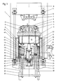
- the drawing devices or presses 1 in FIGS. 1, 2 and 4 consist of a stationary press table 2 with a table support 3 for receiving the lower tool 4 for producing a workpiece, represented by the board 5 which has not yet been machined.
- the board 5 is on a sheet metal holder 6 hung up, which is guided in the lower tool 4 with stamp 4 '.
- the upper tool 7 is connected to the press ram 8.
- the sheet metal holder 6 is supported by pressure bolts 9 on a pressure cheek 10 - also called pressure cushion or die cushion.
- tension rods or connecting rods 12 are articulated on the press ram 8 via bolts 11, which in turn are connected in their lower region via bolts 11 to a lower sheet metal holder frame 13.
- the sheet metal holder frame 13 is accordingly guided rigidly with the press ram 8 within the press table 2.
- Four piston-cylinder units 14 to 16 are fixedly connected to the sheet metal holder frame 13, the cylinder being designated by reference numeral 14 and the piston rod by reference numeral 15.
- the piston 16 running in the cylinder 14 divides the inner pressure chamber 17 into an upper pressure chamber 18 and into a lower pressure chamber 19.
- the piston rods 15 are firmly connected in their upper region to the underside of the die cushion 10 via a holder 20.
- the die cushion 10 is hereby supported by four piston-cylinder units 14 to 16 in its corner regions, so that a targeted influence on the sheet metal holder of the sheet metal holder 6 is possible.
- the pressure cheek 10 is guided in the press table 2 and is moved upwards by a central piston-cylinder unit 21 to 23, the cylinder stationary in the press table with reference number 21 and that in the cylinder housing Movable piston rod acting on the die cushion 10 is designated by reference numeral 22.
- the piston itself is identified by reference number 23.
- the piston-cylinder unit 21 to 23 is designed as a prestressed compressed air cylinder and is closed in the lower region by a flange 24.
- the piston rod 22 is extended downwards by the piston 23 through a further piston rod 25 with a smaller cross section, which projects downward through the flange 24 and is provided at its end with a further piston 26 in a cylinder housing 27.
- the pressure chamber 28 arranged above the piston 26 is closed by a check valve 29 as a pressure chamber with a damping function and is used via a throttle circuit (not shown in detail) to dampen the upward movement of the upper piston 23 before its upper end stop.
- the pressure chamber 30 of the piston-cylinder unit 21 to 23 lying below the piston 23 is prestressed with compressed air via the pressure line 31 and a proportional valve 32 with accumulator 33.
- the further valve 34 serves to equalize the pressure.
- the upper piston rod 15 is passed through the piston 16 in the piston-cylinder unit 14 to 16 and continued in the lower region in the pressure chamber 19 as a piston rod 15 '.
- this piston rod region 15 ' is passed through the sheet metal holder frame 13 and attached to a cross member 35 at the lower end.
- the 1 furthermore has a control piston 36, 37 integrated in the cylinder housing 14, the upper cylinder bore 36 in the cylinder housing 14 is arranged parallel to the cylinder space or pressure space 17 and extends downward through the sheet metal holder frame 13.
- the continued in the sheet metal holder frame is designated 36 '.
- the cylinder bore 36, 36 ' is penetrated from below by a piston rod 37 which is hinged to an actuator 38 for adjusting the starting position of the piston rod 37.
- the height adjustment motor 38 is itself attached to the crossbar 35.
- the press ram 8 moves with the upper tool 7 including the four tie rods 12 with the sheet metal holder frame 13 fastened thereon downward in the direction of the lower tool 4.
- the four cylinder housings 14 connected to the sheet metal holder frame 13 likewise move downwards, the hydraulic oil contained in the upper pressure chamber 18 of the piston-cylinder units 14 to 16 having to escape.
- the upper pressure chamber 18 and the lower pressure chamber 19 of each piston-cylinder unit 14 to 16 are connected to one another via a pressure line 39 and a proportional valve 40, so that the pressure medium from the pressure chamber 18 into the pressure chamber 19 during the downward movement of the Cylinder housing 14 can flow without pressure.
- the die cushion 10 itself is held in its upper position by the piston-cylinder unit 21 to 23, which is designed as a pneumatic cylinder unit, the pressure being applied via the proportional valve 32.
- the upper stop is formed by the stop of the lower piston 26 of the lower hydraulic piston-cylinder unit 26, 27 serves as a damping unit. To maintain this position, only a slight pressure of the reservoir 33 is required.
- the proportional valve 40 is closed shortly before the upper tool 7 is placed on the board 5 and thus on the sheet metal holder 6.
- a pressure accumulator 42, 42 ' is opened by means of the proportional valve 41, which suddenly applies pressure to the lower pressure chamber 19, as a result of which the piston 16 and thus the die cushion 10 are pressed upwards.
- the proportional valve 41 then also takes over, if necessary, a program-controlled regulation of the pressure profile of each individual piston-cylinder unit 14 to 16.
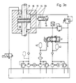
- the components, which are also shown in FIG. 3a, are required as measurement and control variables.
- FIG. 3b In the representation of the invention according to FIG. 1, in contrast to that according to FIG. 2, an additional acceleration device for the sheet metal holder 6 is provided.
- the circuit diagram for this is shown in Fig. 3b.
- the control piston 37 already described in relation to FIG. 1 moves in one Cylinder bore 36 or 36 'upwards.
- this upward movement of the control piston 37 represents a downward movement of the cylinder housing 14, connected to the downward movement of the press ram 8 and the sheet metal holder frame 13 in connection with the cylinder housings 14.
- the control piston 37 is rigidly connected via the cross member 35 to the piston rods 15, 15 ' .
- the cylinder bore 36 is connected to the upper pressure chamber 18 via a pressure line 43 and to the lower pressure chamber 19 of the pressure chamber or cylinder chamber 17 via a lower line 44.
- the flow of the pressure line 43 to the upper pressure chamber 18 can be controlled via a proportional valve 45 and a corresponding control valve 46.
- Fig. 1 in the left piston-cylinder unit 14 to 16.
- the right piston-cylinder unit 14 to 16 contains only a bare through hole 43 '.
- the acceleration device is used as follows:
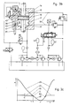
- this acceleration process is shown again as a curve.
- the X-axis shows the angle of rotation of the rotating plunger drive, the Y-axis the plunger stroke.
- Curve 48 shows the tappet path. The bottom dead center is marked with UT.
- the path of the die cushion 10 is shown at 49.
- the inlet bore 44 to the lower pressure chamber 19 is closed by the control curve 47 of the control piston 37 and the die cushion 10 is accelerated by the amount a ⁇ 30 mm before the upper tool 7 touches the sheet holder 6 at point 51 at the angle of rotation X2.
- the path of the die cushion 10 according to curve 49 is the same as the path of the sheet metal holder 6. This pre-acceleration dampens the impact of the upper tool on the sheet metal holder. From point 51 to point 52 then the sheet metal holder and the press ram moves over the same curve path 48 '.
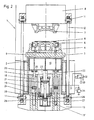
- the design of the piston-cylinder unit 14 to 16 is configured somewhat differently.
- the lower piston rod 15 ', d. H. the control schemes shown in FIGS. 3a and 3b do not apply here.
- the pressure medium accordingly not only swings from the upper pressure chamber 18 into the lower pressure chamber 19, but is controlled from the outside.
- the lower pressure chamber 19 ' is connected via a bore 55 to a further piston-cylinder unit 56 to 58, 56 representing the cylinder housing and 57 the piston rod.
- the piston 58 runs in the cylinder housing 56.
- the piston-cylinder unit 56 to 58 is firmly integrated in the sheet metal holding frame and moves with it.
- the piston rod 57 hits a lower stop 59, the height position "h" of which can be adjusted via the servomotor 60.
- the stop 59 with the servomotor 60 is arranged in a stationary manner in the press table 2.
- the piston 58 is now pushed upward within the cylinder housing 56, which leads to an increase in pressure in the lower pressure chamber 19 'and thus to the actual sheet metal holder pressure.
- the proportional valve 61 regulates the pressure in the lower pressure chamber 19 according to predetermined values. A path-dependent program-controlled pressurization of the sheet metal holder 6 is thus possible.
- the clamped between the sheet metal holder 6 and the lower tool 7 5 initially moves during the distance s to the punch 4 'of the lower tool 4 before the actual drawing process begins.
- the pressure in the piston-cylinder units 14 to 16 is Cylinder unit 56 to 58 constructed, which forms the holding pressure for the sheet metal holder. Thereafter, no further energy is required on the sheet metal holder, except that which is required by the piston-cylinder unit 56 to 58 to compensate for any pressure losses.
- the system is tense.
- the pressure cheek 10 is moved upwards by the pneumatic piston-cylinder unit 21 to 23, the damping device of the hydraulic piston-cylinder unit 26, 27 damping the upper impact.
- the oil column under the pressure piston 16 can then flow back into the accumulator 52 via the valve 53. This takes place during the upward movement of the press ram 8 and thus of the sheet metal holder frame 13 with the cylinder housing 14.
- the pressure medium flows from the lower pressure chamber 19 into the upper pressure chamber 18 in this case.
- the invention is not restricted to the exemplary embodiment shown and described. Rather, it also includes all professional developments and modifications without their own inventive content.
Landscapes
- Engineering & Computer Science (AREA)
- Mechanical Engineering (AREA)
- Presses And Accessory Devices Thereof (AREA)
- Shaping Metal By Deep-Drawing, Or The Like (AREA)
- Press Drives And Press Lines (AREA)
Applications Claiming Priority (2)
| Application Number | Priority Date | Filing Date | Title |
|---|---|---|---|
| DE3930348 | 1989-09-12 | ||
| DE3930348 | 1989-09-12 |
Publications (3)
| Publication Number | Publication Date |
|---|---|
| EP0417752A2 true EP0417752A2 (fr) | 1991-03-20 |
| EP0417752A3 EP0417752A3 (en) | 1991-06-05 |
| EP0417752B1 EP0417752B1 (fr) | 1994-03-02 |
Family
ID=6389201
Family Applications (1)
| Application Number | Title | Priority Date | Filing Date |
|---|---|---|---|
| EP90117535A Expired - Lifetime EP0417752B1 (fr) | 1989-09-12 | 1990-09-12 | Presse mécanique ou hydraulique avec dispositif d'étirage ou d'emboutissage pour presse à plusieurs étapes |
Country Status (3)
| Country | Link |
|---|---|
| EP (1) | EP0417752B1 (fr) |
| DE (1) | DE59004758D1 (fr) |
| ES (1) | ES2049378T3 (fr) |
Cited By (5)
| Publication number | Priority date | Publication date | Assignee | Title |
|---|---|---|---|---|
| EP0635320A1 (fr) * | 1993-07-24 | 1995-01-25 | Umformtechnik ERFURT GmbH | Serre-flan pour presses à simple effet en particulier pour presses mécaniques et presses de transfert |
| EP0768127A3 (fr) * | 1995-10-14 | 1997-04-23 | SCHULER PRESSEN GmbH & Co. | Dispositif d'étirage pour une presse |
| WO2006094485A1 (fr) * | 2005-03-07 | 2006-09-14 | Müller Weingarten AG | Ensemble coussin d'emboutissage a entrainement par commande numerique et a coussin hydraulique |
| CN103476517A (zh) * | 2011-04-12 | 2013-12-25 | 舒乐绞扭机有限责任公司 | 用于运行带有下驱动装置的压力机的方法和根据该方法运行的压力机 |
| EP2712688A1 (fr) * | 2012-09-28 | 2014-04-02 | Siemens Aktiengesellschaft | Entraînement de coussin hydraulique et procédé de fonctionnement d'un entraînement de coussin hydraulique |
Families Citing this family (2)
| Publication number | Priority date | Publication date | Assignee | Title |
|---|---|---|---|---|
| WO2002087801A1 (fr) | 2001-04-27 | 2002-11-07 | Schuler Pressen Gmbh & Co.Kg | Dispositif d'emboutissage hydraulique |
| DE10125078B4 (de) * | 2001-04-27 | 2007-04-05 | Schuler Pressen Gmbh & Co. Kg | Hydraulische Zieheinrichtung |
Family Cites Families (4)
| Publication number | Priority date | Publication date | Assignee | Title |
|---|---|---|---|---|
| DE3406526C2 (de) * | 1984-02-23 | 1987-01-15 | Maschinenfabrik Müller-Weingarten AG, 7987 Weingarten | Einfachwirkende Presse mit einem Ziehkissen im Pressentisch und einem Schiebetisch |
| DE3717768A1 (de) * | 1987-05-26 | 1988-12-08 | Schuler Gmbh L | Zieheinrichtung im pressentisch einer presse |
| DD272963A3 (de) * | 1987-08-26 | 1989-11-01 | Warnke Umformtech Veb K | Pneumo-hydraulisches kissen fuer pressen zum abstreifen der blechteile aus dem werkzeug nach dem umformprozess bzw. zum gegenhalten waehrend des ziehvorganges |
| DD267205A1 (de) * | 1987-12-24 | 1989-04-26 | Warnke Umformtech Veb K | Hydraulischer blechhalter fuer einfachwirkende pressen |
-
1990
- 1990-09-12 EP EP90117535A patent/EP0417752B1/fr not_active Expired - Lifetime
- 1990-09-12 ES ES90117535T patent/ES2049378T3/es not_active Expired - Lifetime
- 1990-09-12 DE DE90117535T patent/DE59004758D1/de not_active Expired - Fee Related
Cited By (8)
| Publication number | Priority date | Publication date | Assignee | Title |
|---|---|---|---|---|
| EP0635320A1 (fr) * | 1993-07-24 | 1995-01-25 | Umformtechnik ERFURT GmbH | Serre-flan pour presses à simple effet en particulier pour presses mécaniques et presses de transfert |
| EP0768127A3 (fr) * | 1995-10-14 | 1997-04-23 | SCHULER PRESSEN GmbH & Co. | Dispositif d'étirage pour une presse |
| US5746084A (en) * | 1995-10-14 | 1998-05-05 | Schuler Pressen Gmbh & Co. | Drawing mechanism for a press |
| WO2006094485A1 (fr) * | 2005-03-07 | 2006-09-14 | Müller Weingarten AG | Ensemble coussin d'emboutissage a entrainement par commande numerique et a coussin hydraulique |
| CN103476517A (zh) * | 2011-04-12 | 2013-12-25 | 舒乐绞扭机有限责任公司 | 用于运行带有下驱动装置的压力机的方法和根据该方法运行的压力机 |
| CN103476517B (zh) * | 2011-04-12 | 2016-11-09 | 舒乐绞扭机有限责任公司 | 用于运行带有下驱动装置的压力机的方法和根据该方法运行的压力机 |
| EP2712688A1 (fr) * | 2012-09-28 | 2014-04-02 | Siemens Aktiengesellschaft | Entraînement de coussin hydraulique et procédé de fonctionnement d'un entraînement de coussin hydraulique |
| US9346095B2 (en) | 2012-09-28 | 2016-05-24 | Siemens Aktiengesellschaft | Die cushion drive and method for operating a die cushion drive |
Also Published As
| Publication number | Publication date |
|---|---|
| DE59004758D1 (de) | 1994-04-07 |
| EP0417752A3 (en) | 1991-06-05 |
| ES2049378T3 (es) | 1994-04-16 |
| EP0417752B1 (fr) | 1994-03-02 |
Similar Documents
| Publication | Publication Date | Title |
|---|---|---|
| DE19521050C2 (de) | Kniehebel-Antriebsvorrichtung | |
| DE2830779C2 (de) | Hydraulische Doppeldruckpresse | |
| EP3115190B1 (fr) | Dispositif et procede de commande de l'entrainement principal d'une presse pour decoupage de precision | |
| DE4112656A1 (de) | Zieheinrichtung in einer presse zum ziehen von blechformteilen | |
| DE2852303A1 (de) | Schmiedepresse, insbesondere freiform- schmiedepresse, in unterflurbauart | |
| EP0417752B1 (fr) | Presse mécanique ou hydraulique avec dispositif d'étirage ou d'emboutissage pour presse à plusieurs étapes | |
| DE10005023C2 (de) | Feinschneidpresse | |
| DE4028921A1 (de) | Mechanische oder hydraulische presse mit zieheinrichtung oder ziehstufe einer stufenpresse | |
| EP0417754B1 (fr) | Presse mécanique ou hydraulique avec dispositif d'étirage ou d'emboutissage pour presse à plusieurs étapes | |
| EP0605698B1 (fr) | Presse a leviers articules | |
| DE19822436A1 (de) | Verfahren zum Betrieb einer hydraulischen Presse | |
| DE4122128A1 (de) | Hydroelastische tiefzieheinrichtung | |
| EP0417753B1 (fr) | Presse mécanique ou hydraulique avec dispositif d'étirage ou d'emboutissage pour presse à plusieurs étapes | |
| EP0635320B1 (fr) | Serre-flan pour presses à simple effet en particulier pour presses mécaniques et presses de transfert | |
| DE4016838A1 (de) | Ziehapparat in einer presse | |
| WO1999054123A1 (fr) | Procede de fonctionnement d'une presse hydraulique | |
| DE10117578A1 (de) | Ziehpresse | |
| WO2008064619A1 (fr) | Presse de formage présentant une fonction de coussin pneumatique intégrée au plateau coulissant | |
| DE19643396A1 (de) | Hydraulische Steuereinrichtung | |
| DE4028919A1 (de) | Mechanische oder hydraulische presse mit zieheinrichtung oder ziehstufe einer stufenpresse | |
| DE4419676A1 (de) | Hydraulisch gekoppelter Blechhalter | |
| DE3602236C2 (fr) | ||
| DE4028920A1 (de) | Mechanische oder hydraulische presse mit zieheinrichtung oder ziehstufe einer stufenpresse | |
| DE19639220A1 (de) | Einrichtung zur Vorbeschleunigung vom Blechhalter einfachwirkender Pressen | |
| DE3835376A1 (de) | Hydraulischer blechhalter fuer einfachwirkende pressen |
Legal Events
| Date | Code | Title | Description |
|---|---|---|---|
| PUAI | Public reference made under article 153(3) epc to a published international application that has entered the european phase |
Free format text: ORIGINAL CODE: 0009012 |
|
| AK | Designated contracting states |
Kind code of ref document: A2 Designated state(s): DE ES FR GB IT SE |
|
| PUAL | Search report despatched |
Free format text: ORIGINAL CODE: 0009013 |
|
| AK | Designated contracting states |
Kind code of ref document: A3 Designated state(s): DE ES FR GB IT SE |
|
| 17P | Request for examination filed |
Effective date: 19910808 |
|
| 17Q | First examination report despatched |
Effective date: 19930302 |
|
| GRAA | (expected) grant |
Free format text: ORIGINAL CODE: 0009210 |
|
| AK | Designated contracting states |
Kind code of ref document: B1 Designated state(s): DE ES FR GB IT SE |
|
| PG25 | Lapsed in a contracting state [announced via postgrant information from national office to epo] |
Ref country code: SE Free format text: THE PATENT HAS BEEN ANNULLED BY A DECISION OF A NATIONAL AUTHORITY Effective date: 19940302 Ref country code: GB Effective date: 19940302 |
|
| REF | Corresponds to: |
Ref document number: 59004758 Country of ref document: DE Date of ref document: 19940407 |
|
| ET | Fr: translation filed | ||
| REG | Reference to a national code |
Ref country code: ES Ref legal event code: FG2A Ref document number: 2049378 Country of ref document: ES Kind code of ref document: T3 |
|
| ITF | It: translation for a ep patent filed | ||
| GBV | Gb: ep patent (uk) treated as always having been void in accordance with gb section 77(7)/1977 [no translation filed] |
Effective date: 19940302 |
|
| PLBE | No opposition filed within time limit |
Free format text: ORIGINAL CODE: 0009261 |
|
| STAA | Information on the status of an ep patent application or granted ep patent |
Free format text: STATUS: NO OPPOSITION FILED WITHIN TIME LIMIT |
|
| 26N | No opposition filed | ||
| PGFP | Annual fee paid to national office [announced via postgrant information from national office to epo] |
Ref country code: DE Payment date: 20020906 Year of fee payment: 13 |
|
| PGFP | Annual fee paid to national office [announced via postgrant information from national office to epo] |
Ref country code: ES Payment date: 20020911 Year of fee payment: 13 |
|
| PGFP | Annual fee paid to national office [announced via postgrant information from national office to epo] |
Ref country code: FR Payment date: 20020918 Year of fee payment: 13 |
|
| PG25 | Lapsed in a contracting state [announced via postgrant information from national office to epo] |
Ref country code: ES Free format text: LAPSE BECAUSE OF NON-PAYMENT OF DUE FEES Effective date: 20030913 |
|
| PG25 | Lapsed in a contracting state [announced via postgrant information from national office to epo] |
Ref country code: DE Free format text: LAPSE BECAUSE OF NON-PAYMENT OF DUE FEES Effective date: 20040401 |
|
| PG25 | Lapsed in a contracting state [announced via postgrant information from national office to epo] |
Ref country code: FR Free format text: LAPSE BECAUSE OF NON-PAYMENT OF DUE FEES Effective date: 20040528 |
|
| REG | Reference to a national code |
Ref country code: FR Ref legal event code: ST |
|
| REG | Reference to a national code |
Ref country code: ES Ref legal event code: FD2A Effective date: 20030913 |
|
| PG25 | Lapsed in a contracting state [announced via postgrant information from national office to epo] |
Ref country code: IT Free format text: LAPSE BECAUSE OF NON-PAYMENT OF DUE FEES;WARNING: LAPSES OF ITALIAN PATENTS WITH EFFECTIVE DATE BEFORE 2007 MAY HAVE OCCURRED AT ANY TIME BEFORE 2007. THE CORRECT EFFECTIVE DATE MAY BE DIFFERENT FROM THE ONE RECORDED. Effective date: 20050912 |