EP0417795B1 - Kraftstoffeinspritzsystem und Verfahren für Brennkraftmaschinen - Google Patents
Kraftstoffeinspritzsystem und Verfahren für Brennkraftmaschinen Download PDFInfo
- Publication number
- EP0417795B1 EP0417795B1 EP90117676A EP90117676A EP0417795B1 EP 0417795 B1 EP0417795 B1 EP 0417795B1 EP 90117676 A EP90117676 A EP 90117676A EP 90117676 A EP90117676 A EP 90117676A EP 0417795 B1 EP0417795 B1 EP 0417795B1
- Authority
- EP
- European Patent Office
- Prior art keywords
- fuel
- engine
- idle speed
- injection
- injection valve
- Prior art date
- Legal status (The legal status is an assumption and is not a legal conclusion. Google has not performed a legal analysis and makes no representation as to the accuracy of the status listed.)
- Expired - Lifetime
Links
- 238000002347 injection Methods 0.000 title claims description 86
- 239000007924 injection Substances 0.000 title claims description 86
- 239000000446 fuel Substances 0.000 title claims description 83
- 238000000034 method Methods 0.000 title claims description 8
- 238000002485 combustion reaction Methods 0.000 claims description 19
- 230000006835 compression Effects 0.000 claims description 8
- 238000007906 compression Methods 0.000 claims description 8
- 238000011217 control strategy Methods 0.000 claims description 4
- 230000000977 initiatory effect Effects 0.000 description 6
- 230000000694 effects Effects 0.000 description 4
- 238000001816 cooling Methods 0.000 description 3
- 238000010276 construction Methods 0.000 description 2
- 238000010586 diagram Methods 0.000 description 2
- 229920006395 saturated elastomer Polymers 0.000 description 2
- 238000004804 winding Methods 0.000 description 2
- 238000004378 air conditioning Methods 0.000 description 1
- 238000013459 approach Methods 0.000 description 1
- 239000002826 coolant Substances 0.000 description 1
- 230000003111 delayed effect Effects 0.000 description 1
- 229930195733 hydrocarbon Natural products 0.000 description 1
- 150000002430 hydrocarbons Chemical class 0.000 description 1
- 238000012986 modification Methods 0.000 description 1
- 230000004048 modification Effects 0.000 description 1
- 230000006641 stabilisation Effects 0.000 description 1
- 238000011105 stabilization Methods 0.000 description 1
- XLYOFNOQVPJJNP-UHFFFAOYSA-N water Substances O XLYOFNOQVPJJNP-UHFFFAOYSA-N 0.000 description 1
Images


Classifications
-
- F—MECHANICAL ENGINEERING; LIGHTING; HEATING; WEAPONS; BLASTING
- F02—COMBUSTION ENGINES; HOT-GAS OR COMBUSTION-PRODUCT ENGINE PLANTS
- F02D—CONTROLLING COMBUSTION ENGINES
- F02D31/00—Use of speed-sensing governors to control combustion engines, not otherwise provided for
- F02D31/001—Electric control of rotation speed
- F02D31/007—Electric control of rotation speed controlling fuel supply
- F02D31/008—Electric control of rotation speed controlling fuel supply for idle speed control
-
- F—MECHANICAL ENGINEERING; LIGHTING; HEATING; WEAPONS; BLASTING
- F02—COMBUSTION ENGINES; HOT-GAS OR COMBUSTION-PRODUCT ENGINE PLANTS
- F02D—CONTROLLING COMBUSTION ENGINES
- F02D41/00—Electrical control of supply of combustible mixture or its constituents
- F02D41/30—Controlling fuel injection
- F02D41/32—Controlling fuel injection of the low pressure type
- F02D41/34—Controlling fuel injection of the low pressure type with means for controlling injection timing or duration
- F02D41/345—Controlling injection timing
-
- F—MECHANICAL ENGINEERING; LIGHTING; HEATING; WEAPONS; BLASTING
- F02—COMBUSTION ENGINES; HOT-GAS OR COMBUSTION-PRODUCT ENGINE PLANTS
- F02B—INTERNAL-COMBUSTION PISTON ENGINES; COMBUSTION ENGINES IN GENERAL
- F02B75/00—Other engines
- F02B75/02—Engines characterised by their cycles, e.g. six-stroke
- F02B2075/022—Engines characterised by their cycles, e.g. six-stroke having less than six strokes per cycle
- F02B2075/025—Engines characterised by their cycles, e.g. six-stroke having less than six strokes per cycle two
-
- F—MECHANICAL ENGINEERING; LIGHTING; HEATING; WEAPONS; BLASTING
- F02—COMBUSTION ENGINES; HOT-GAS OR COMBUSTION-PRODUCT ENGINE PLANTS
- F02D—CONTROLLING COMBUSTION ENGINES
- F02D41/00—Electrical control of supply of combustible mixture or its constituents
- F02D41/30—Controlling fuel injection
- F02D41/38—Controlling fuel injection of the high pressure type
- F02D2041/389—Controlling fuel injection of the high pressure type for injecting directly into the cylinder
-
- F—MECHANICAL ENGINEERING; LIGHTING; HEATING; WEAPONS; BLASTING
- F02—COMBUSTION ENGINES; HOT-GAS OR COMBUSTION-PRODUCT ENGINE PLANTS
- F02D—CONTROLLING COMBUSTION ENGINES
- F02D2400/00—Control systems adapted for specific engine types; Special features of engine control systems not otherwise provided for; Power supply, connectors or cabling for engine control systems
- F02D2400/04—Two-stroke combustion engines with electronic control
-
- Y—GENERAL TAGGING OF NEW TECHNOLOGICAL DEVELOPMENTS; GENERAL TAGGING OF CROSS-SECTIONAL TECHNOLOGIES SPANNING OVER SEVERAL SECTIONS OF THE IPC; TECHNICAL SUBJECTS COVERED BY FORMER USPC CROSS-REFERENCE ART COLLECTIONS [XRACs] AND DIGESTS
- Y02—TECHNOLOGIES OR APPLICATIONS FOR MITIGATION OR ADAPTATION AGAINST CLIMATE CHANGE
- Y02T—CLIMATE CHANGE MITIGATION TECHNOLOGIES RELATED TO TRANSPORTATION
- Y02T10/00—Road transport of goods or passengers
- Y02T10/10—Internal combustion engine [ICE] based vehicles
- Y02T10/40—Engine management systems
Definitions
- This invention relates to a fuel injection system and a method of injecting fuel in an internal combustion engine so as to provide better and more stable idle operation.
- direct cylinder injection can be particularly useful in two cycle crankcase compression internal combustion engines as a method for controlling exhaust emissions and running characteristics. That is, direct cylinder injection can, under some circumstances, improve misfiring, uneven combustion and the emission of hydrocarbons. Although direct cylinder fuel injection can improve these characteristics, the direct cylinder injection systems and methods previously proposed have not been completely satisfactory in insuring good and stable idle speed.
- US-A-4379332 discloses means for controlling the idle speed of the engine by means controlling the injection timing and the amount of fuel injected in a compression ignition engine. It is desirable to provide an improved arrangement which allows to further suppress fluctuations in idle speed under varying operating conditions.
- WO-A-87/00 580 discloses a 2-stroke crank case compression engine with an injector injecting fuel and air into the combustion chamber.
- Figure 1 is a partial cross sectional view taken through the combustion chamber of an engine having a fuel injection system construction and operated in accordance with an embodiment of the invention.
- Figure 2 is a schematic block diagram showing the components of the injection system.
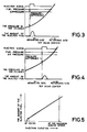
- Figure 3 is a graphic view showing the fuel delivery in relation to the injection timing, air pressure and fuel pressure characteristics under one running condition.
- Figure 4 is a graphic view, in part similar to Figure 3, showing the characteristics during another phase of operation.
- Figure 5 is a graphic view showing the amount of fuel injection and the injection duration under all running speeds and conditions.
- Figure 6 is a graphic view showing how the starting of time of injection will vary idle speed even if the duration of fuel injection is maintained constant and also shows two different types of control routines.
- Figure 7 is a timing curve showing the fuel injection initiation and duration under idle conditions.
- Figure 8 is a graphic view showing how the duration of fuel injection effects idle speed when injection starting time is held constant.
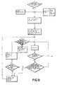
- Figure 9 is a block diagram showing a form of control routine which may be utilized in conjunction with the invention.
- FIG. 1 a portion of an internal combustion engine having a fuel injection system constructed and operated in accordance with the invention is partially depicted. Since the invention deals with the fuel injection system, illustration of the complete engine is not believed to be necessary in order to understand the construction and operation of the invention.
- the engine depicted is of the two cycle crankcase compression type. Although the invention may be employed in conjunction with four cycle engines, it has particular utility in conjunction with two cycle engines due to the aforenoted difficulties in maintaining good running conditions under idle with such engines while maintaining the idle speed, combustion and exhaust emission within desired limits.
- the engine includes a cylinder head 11 which has a recess 12 which defines partially a combustion chamber 13.
- the combustion chamber 13 is defined by the cylinder head recess 12, the head of the piston and the cylinder bore (not shown).
- a spark plug 14 is threaded into the cylinder head 11 and has its gap 15 disposed appropriately in the combustion chamber 13.
- a cooling jacket 16 is formed in the cylinder head 11 and coolant is circulated through this cooling jacket in a known manner for engine cooling.
- a fuel injector is mounted within a bore 18 formed in the cylinder head 11.
- the injector 17 is a fuel/air injector. It is to be understood, however, that the invention may be employed with other types of fuel injectors than air/fuel injectors. For example, the invention may be utilized with injectors that inject only fuel, but the invention has particular utility in conjunction with air/fuel injectors.
- the injector 17 includes a body assembly 19 that includes a main housing portion 21 that has a cylindrical part 22 that is received within the bore 18.
- the bore 18 will be threaded and the cylindrical part 22 will be threaded so as to attach the injector 17 to the cylinder head 11.
- the main body part 21 has a bore 23 in which a valve sleeve 24 is positioned. There is a gap between this bore 23 and the valve sleeve 24 so as to provide a chamber into which fuel is injected by a fuel injector 25.
- the injector 25 is mounted in the housing port 21 and communicates with this cavity through a delivery port 26.
- the cavity terminates at its lower end in a valve seat portion in which a plurality of delivery ports 27 are positioned.
- a conical head 28 of an injection valve 29 opens and closes the ports 27 and, accordingly, communicates the fuel with the combustion chamber 13 when the valve 29 is open.
- the valve body 24 is also formed with a bore 31 and an air chamber is provided within the bore 31 by a reduced diameter portion 32 of the valve 29 and a further recess 33 formed in the valve member 24 adjacent its seat portion. Pressurized air is delivered to this chamber from an air inlet port 34 formed in a manifold 35 which is affixed suitably to the main body part 21 of the housing assembly 19 of the injector 17.
- a valve guide 36 has a bore that receives the upper end of the stem portion 32 of the valve 29.
- An armature 37 is affixed to this stem portion by means of a nut 38.
- a coil compression spring 39 normally urges the valve 29 to its closed position as shown in Figure 1.
- An electrical solenoid winding 41 is contained within an actuator portion 42 of the injector 17 and when energized, attracts the armature 37 and moves the control valve 29 to its open position so that fuel and air will be injected into the combustion chamber 13.
- the amount of fuel injected can be varied in a wide variety of manners and the operation of the fuel injector 25 may be initiated either before the valve 29 is opened or after. Any such control strategies are within the spirit and scope of the invention.
- the air pressure delivered to the port 34 can also be varied as desired so as to change the fuel/air injection characteristics. Again, this particular part of the strategy is not critical to the invention and the invention may be utilized in conjunction with any wide variety of strategies of varying air pressure and/or the timing and duration of operation of the injector 25.
- the effect of the operation of the method and structure incorporating the invention will depend upon the air pressure and the way fuel is delivered. This relationship will be described later.
- the reference numeral 43 indicates the control element for the air/fuel injector 17.
- This control element 43 controls the main control valve 29 of the injector 17 and also the fuel injector 25 of this injector. If desired, there may also be a control for air pressure. Although this is not particularly necessary, it may be utilized in conjunction with the invention.
- a fuel injection correction unit 46 receives both the engine speed signal b and also an input from a device that selects the desired idling speed in accordance with certain parameters such as the temperature, the accessory load on the engine and the like. This fuel injection timing corrector outputs a signal ⁇ to the controller 43 for adjusting the initiation of fuel injection and the duration of fuel injection in accordance with a scheme which will be discussed later.
- the timing or duration of the injection signal is maintained constant and the air and fuel pressures are maintained constant. It is preferred that the fuel pressure be greater than the air pressure and it will be noted that compression pressure in the cylinder increases, as is well known, as the piston approaches top dead center.
- the idle speed can be easily changed only by adjusting the timing of the initiation of fuel injection as opposed to the duration.
- the injector duration is increased as shown in Figure 5. This figure shows that the amount of fuel injected at idle can vary, but as the engine moves off idle, the amount of fuel injected is changed by changing the duration of opening of the valve 29. It is assumed under this condition that fuel injection by the injector 25 is governed by the entire time when injector valve 29 is open.
- the injection duration at idle is set at a fixed amount which depends upon the desired engine speed.
- the initial air pressure is also set so that the fuel injection for the desired idling speed can be started before the pressure in the cylinder becomes too great so as to preclude fuel from being discharged when the valve 29 is open. This time is referred to as the time when the pressure curve is saturated. It should be obvious to those skilled in the art that if the fuel injection is delayed until just before top dead center, the only way adequate fuel can be delivered is by increasing substantially the injection and air pressures and this obviously raises the cost of the system significantly.
- Figure 6 is a graphic view showing how the effect of varying the injection starting time will effect idle speed even if fuel duration is constant.
- reference to the initiation of fuel injection and the duration refers to the time when the valve 29 is open and independent of the actuation of the fuel injector 25. That is, the invention is utilized in conjunction with systems where in the fuel is all precharged into the injector 17 before the valve 29 is opened or other control routines wherein the fuel is injected by the injector 25 only after the valve 29 is opened.
- the principles of the invention are the same regardless of the internal strategy under which the injector 17 operates.
- FIG 6 this figure illustrates a specific example of the invention when the fuel injection duration is held constant at 1.5 milliseconds and ignition timing is approximately 328° to 332° after top dead center. It will be seen that as the starting time of injection is advanced, the idle speed increases significantly. There comes a point in time (the point A) when the pressure curve is saturated and the pressure in the combustion chamber is so high that fuel cannot be injected and the engine will stall.
- initial injection timing is begun at approximately 315° after top dead center.
- Figure 8 shows two timing curves.
- the idle speed varies from the set speed by more than a predetermined amount, for example, more than 30 rpm when the desired idle speed is in the range of 750 rpm, then it is more desirable to adjust the idle speed by adjusting the initiation of injection timing and not the amount of fuel injected. If the idle speed variation is less than 30 rpm at this speed range, then it is preferable to adjust or fine tune the idle speed by changing the injection duration.
- Figure 7 illustrates how idle speed can be fine tuned by changing injection duration. This is a figure showing engine speed in relation to injection duration and assuming that injection starting timing is held constant at 315° after top dead center. It will be seen from this curve that variations in injection duration can achieve fine changes in engine idle speed. Therefore, and again referring to Figure 6, if the engine speed varies by more than 300 rpm, in a typical embodiment, then the idle stability is achieved by changing the injection timing as shown at the upper dot-dash portion of this curve. If, however, the engine speed difference is less than 30 rpm, then the engine speed is controlled by changing the duration of fuel injection as shown by the lower dotted control curve.
- Figure 8 shows a scheme by which the aforenoted features can be utilized in order to control idle speed. It is to be understood that this is just one control routine that may be practiced in conjunction with the invention and that other routines are possible.
- the controller 43 makes a determination of whether or not the engine is in its idle condition. This can be done by determining the position of the throttle valve sensor 44. If the throttle valve is at its closed or idle condition, then the program moves forward from the step S1. If it is not, the program merely repeats. If at the step S1 it is determined that the engine is in the idling condition, then at a point S2 certain parameters of the engine which will determine the desired idle speed are sensed. These may constitute water temperature and accessory load, determined at the points S3 and S4.
- the accessory load may be such features as headlights, air conditioning compressor, power steering, et cetera, all of which tend to reduce the idle speed of the engine and require a higher speed due to the load required to drive these accessories. These features are all preprogrammed into the control unit 46 that preprograms the aimed idling speed into the controller 43.
- the program then moves to the step S5 so that the desired idle speed is set by the input from the unit 46. Then the injection timing and the injection duration are initially set at the step S6. During a cycle of operation, the program then moves to the step S7 so as to accomplish fuel injection. The program then moves to the step S8 to determine whether the engine is still in the idling condition by checking the condition of the throttle valve by the sensor 44. If the operator has called for a change in speed, then the program repeats back to the start to again begin the routine only when an idling condition is again sensed.
- step S8 the program moves to the step S9 to determine whether there is a difference between the engine speed detected by the detector 45 and the desired idle speed. If there is not, the program moves back to the step S7 and continues injection at the previously set rate.
- step S9 If it is determined at the step S9 that the actual engine speed is not the desired idle speed, then the program moves to the step S10 to determine the amount of speed difference. The comparison is made, in the previously described example, whether or not the idle speed varies from the desired idle speed by less than 30 rpm. If it is not, then the program moves to the step S11 so as to change the injection timing (the point at which the injection valve 29 is initially opened). This is done without changing the duration of the fuel injection. Then the program moves again to the step S7 and begins injection again, but at the changed injection timing.
- the program moves to the step S12 so as to set a change in the duration of the opening of the injection valve 29 without changing the timing of start of injection.
- the program then moves to the step S13 to determine if the duration called for is lower than the minimum duration set for the injector 17. If it is lower than that possible, the program moves to the step S14 to set the duration to the lowest limit, assuming that it is not already been set at that limit and the program moves to the step S11 to adjust the injection timing. If at the step S13 it is determined that the injection duration called for is not below the lowest limit, then the program moves to the step S7 and commences injection at the previously set time, but for a different duration.
- start of injection refers to the time when the introduction of fuel into the combustion chamber begins. In the illustrated embodiment, this occurs when the valve 29 is open and regardless of the strategy of the operation of the fuel injector 25.
Landscapes
- Engineering & Computer Science (AREA)
- Chemical & Material Sciences (AREA)
- Combustion & Propulsion (AREA)
- Mechanical Engineering (AREA)
- General Engineering & Computer Science (AREA)
- Electrical Control Of Air Or Fuel Supplied To Internal-Combustion Engine (AREA)
- Fuel-Injection Apparatus (AREA)
- Combined Controls Of Internal Combustion Engines (AREA)
Claims (2)
- Verfahren zur Steuerung einer Kraftstoffeinspritzung in eine Brennkraftmaschine vom Zweitaktmotortyp mit Kurbelgehäuseverdichtung, mit den Schritten der Einspritzung von Kraftstoff direkt in eine Verbrennungskammer (13) des Motors durch eine Zuführungsöffnung, die durch ein Einspritzventil (29) geöffnet und geschlossen wird, Messen der tatsächlichen Leerlaufdrehzahl des Motors, Bestimmen der Veränderung der tatsächlichen Leerlaufdrehzahl von einem Zielwert und Einstellen der Kraftstoffeinspritzsteuerstrategie derart, daß eine im wesentlichen konstante Leerlaufdrehzahl erhalten wird, dadurch gekennzeichnet, daß dann, wenn die erfaßten Veränderungen der Leerlaufdrehzahl größer sind als ein vorgegebener Wert, der Zeitpunkt des Öffnens des Einspritzventiles (29) eingestellt wird, ohne daß die Dauer, für die das Einspritzventil (24) offengehalten wird, geändert wird, derart, daß der Zeitpunkt, wenn das Einspritzventil (29) geöffnet wird, vorverstellt wird, wenn die tatsächliche Leerlaufdrehzahl zu niedrig ist und spätverstellt wird, wenn die Leerlaufdrehzahl zu hoch ist, während für den Fall, daß die Motordrehzahlveränderungen geringer sind als der vorgegebene Wert die Menge des eingespritzten Kraftstoffes geändert wird, ohne daß der Zeitpunkt, zu dem das Einspritzventil (29) geöffnet wird, verändert wird.
- Kraftstoffeinspritzsystem für eine Brennkraftmaschine vom Zweitakttyp mit Kurbelgehäuseverdichtung, mit einem Kraftstoffeinspritzgerät (25), mit einem Einspritzventil (29) zur Zuführung von Kraftstoff direkt zu der Verbrennungskammer des Motors, einer Erfassungseinrichtung zur Erfassung der Leerlaufdrehzahl des Motors und einer Einrichtung zur Veränderung der Steuerstrategie der Kraftstoffeinspritzung in Abhängigkeit von einer erfaßten Veränderung einer tatsächlichen Leerlaufdrehzahl von einem Zielwert derart, daß eine im wesentlichen konstante Leerlaufdrehzahl erhalten wird, gekennzeichnet durch eine Einrichtung zur Einstellung des Zeitpunktes, wenn das Einspritzventil (29) geöffnet wird, ohne daß die Dauer, für die das Einspritzventil (29) offengehalten wird, verändert wird, für den Fall, daß die erfaßten Veränderungen der Leerlaufdrehzahl größer sind als ein vorgegebener Wert, derart, daß der Zeitpunkt, wenn das Einspritzventil (29) geöffnet wird, vorverstellt wird, wenn die tatsächliche Leerlaufdrehzahl zu niedrig ist und spätverstellt wird, wenn die Leerlaufdrehzahl zu hoch ist, während die Einrichtung die eingespritzte Kraftstoffmenge ändert, ohne daß der Zeitpunkt des Öffnens des Einspritzventils (29) geändert wird, für den Fall, daß die Veränderungen der Motordrehzahl geringer sind als ein vorgegebener Wert, und wobei das Kraftstoffeinspritzgerät (25) auch Druckluft in die Verbrennungskammer des Motors einspritzt, wobei das Einspritzventil (29) vorgesehen ist, um sowohl die Zuführung von eingespritzter Luft und eingespritztem Kraftstoff zu steuern.
Applications Claiming Priority (4)
| Application Number | Priority Date | Filing Date | Title |
|---|---|---|---|
| JP237857/89 | 1989-09-13 | ||
| JP23785789 | 1989-09-13 | ||
| JP153121/89 | 1990-06-12 | ||
| JP15312190 | 1990-06-12 |
Publications (2)
| Publication Number | Publication Date |
|---|---|
| EP0417795A1 EP0417795A1 (de) | 1991-03-20 |
| EP0417795B1 true EP0417795B1 (de) | 1994-03-02 |
Family
ID=26481837
Family Applications (1)
| Application Number | Title | Priority Date | Filing Date |
|---|---|---|---|
| EP90117676A Expired - Lifetime EP0417795B1 (de) | 1989-09-13 | 1990-09-13 | Kraftstoffeinspritzsystem und Verfahren für Brennkraftmaschinen |
Country Status (3)
| Country | Link |
|---|---|
| US (1) | US5095873A (de) |
| EP (1) | EP0417795B1 (de) |
| DE (1) | DE69006987T2 (de) |
Families Citing this family (13)
| Publication number | Priority date | Publication date | Assignee | Title |
|---|---|---|---|---|
| JP2975090B2 (ja) * | 1990-11-13 | 1999-11-10 | ヤマハ発動機株式会社 | 燃料噴射制御装置 |
| JP3063939B2 (ja) * | 1992-06-30 | 2000-07-12 | 三信工業株式会社 | 燃料噴射式エンジンの制御装置 |
| AUPN489595A0 (en) * | 1995-08-18 | 1995-09-14 | Orbital Engine Company (Australia) Proprietary Limited | Gaseous fuel direct injection system for internal combustion engines |
| JP3478318B2 (ja) * | 1996-08-27 | 2003-12-15 | 三菱自動車工業株式会社 | 筒内噴射型火花点火式内燃エンジンの制御装置 |
| AUPP070497A0 (en) * | 1997-12-03 | 1998-01-08 | Orbital Engine Company (Australia) Proprietary Limited | Improved method of fuelling an engine |
| JP3092604B2 (ja) | 1998-11-12 | 2000-09-25 | トヨタ自動車株式会社 | 内燃機関 |
| US6349706B1 (en) * | 1998-11-16 | 2002-02-26 | General Electric Company | High injection rate, decreased injection duration diesel engine fuel system |
| US6161527A (en) * | 1999-02-11 | 2000-12-19 | Brunswick Corporation | Air assisted direct fuel injection system |
| JP2002213290A (ja) | 2001-01-19 | 2002-07-31 | Sanshin Ind Co Ltd | 小型船舶における内燃機関のエンジン回転数調整装置 |
| DE10108220A1 (de) * | 2001-02-21 | 2002-09-19 | Bosch Gmbh Robert | Verfahren, Computerprogramm und Steuer- und/oder Regelgerät zum Betreiben einer Brennkraftmaschine sowie Brennkraftmaschine |
| NZ595000A (en) | 2003-12-22 | 2013-03-28 | Gilead Sciences Inc | Imidazo[4,5-c]pyridine derivative for treating viral infections |
| WO2012000029A1 (en) * | 2010-07-01 | 2012-01-05 | Orbital Australia Pty Limited | Method of injecting fuel into an engine |
| CN109154271B (zh) * | 2016-03-23 | 2021-09-28 | 奥比托澳大利亚有限公司 | 燃料喷射系统 |
Citations (1)
| Publication number | Priority date | Publication date | Assignee | Title |
|---|---|---|---|---|
| US4379332A (en) * | 1978-09-25 | 1983-04-05 | The Bendix Corporation | Electronic fuel injection control system for an internal combustion engine |
Family Cites Families (10)
| Publication number | Priority date | Publication date | Assignee | Title |
|---|---|---|---|---|
| US2746441A (en) * | 1952-11-08 | 1956-05-22 | Kremser Johann | Two-stroke cycle internal-combustion engine |
| US2724371A (en) * | 1952-11-26 | 1955-11-22 | Mallory Marion | Internal combustion engine |
| US3196859A (en) * | 1962-08-24 | 1965-07-27 | Outboard Marine Corp | Engine |
| US4463733A (en) * | 1983-02-15 | 1984-08-07 | Deere & Company | Closed loop fuel injection timing control |
| US4597368A (en) * | 1985-02-25 | 1986-07-01 | General Motors Corporation | Engine idle speed control system |
| US4805571A (en) * | 1985-05-15 | 1989-02-21 | Humphrey Cycle Engine Partners, L.P. | Internal combustion engine |
| BR8606801A (pt) * | 1985-07-19 | 1987-10-13 | Orbital Eng Pty | Regulagem de tempo de motores con injecao de combustivel |
| MX172106B (es) * | 1988-02-25 | 1993-12-03 | Orbital Eng Pty | Metodo y sistema mejorados para la inyeccion de combustible en un motor de combustion interna |
| JPH0240052A (ja) * | 1988-07-29 | 1990-02-08 | Fuji Heavy Ind Ltd | 2サイクル直噴エンジンのアイドル回転数制御装置 |
| US4955341A (en) * | 1989-09-18 | 1990-09-11 | General Motors Corporation | Idle control system for a crankcase scavenged two-stroke engine |
-
1990
- 1990-09-10 US US07/580,130 patent/US5095873A/en not_active Expired - Lifetime
- 1990-09-13 EP EP90117676A patent/EP0417795B1/de not_active Expired - Lifetime
- 1990-09-13 DE DE69006987T patent/DE69006987T2/de not_active Expired - Fee Related
Patent Citations (1)
| Publication number | Priority date | Publication date | Assignee | Title |
|---|---|---|---|---|
| US4379332A (en) * | 1978-09-25 | 1983-04-05 | The Bendix Corporation | Electronic fuel injection control system for an internal combustion engine |
Also Published As
| Publication number | Publication date |
|---|---|
| EP0417795A1 (de) | 1991-03-20 |
| US5095873A (en) | 1992-03-17 |
| DE69006987D1 (de) | 1994-04-07 |
| DE69006987T2 (de) | 1994-06-09 |
| JPH04128531A (ja) | 1992-04-30 |
Similar Documents
| Publication | Publication Date | Title |
|---|---|---|
| US5590632A (en) | Apparatus for computing the amount of intake air in internal combustion engine | |
| CA1323532C (en) | Two-fluid fuel injected engines | |
| US4359032A (en) | Electronic fuel injection control system for fuel injection valves | |
| US6647948B2 (en) | Fuel injection control apparatus and fuel injection control method for direct injection engine | |
| EP1041265B1 (de) | Common-Rail-Kraftstoffeinspritzsystem | |
| US5730105A (en) | Idle control for internal combustion engine | |
| US5941223A (en) | Engine control system and method | |
| US5400755A (en) | Combustion control system for in-cylinder injection type two-cycle engine | |
| EP0310652B1 (de) | Druckerzeugung für eine kraftstoffeinspritzanlage der gaseinspritzbauart | |
| EP0417795B1 (de) | Kraftstoffeinspritzsystem und Verfahren für Brennkraftmaschinen | |
| EP1443197B1 (de) | Regelsystem für die Direkteinspritzung des Kraftstoffs | |
| US5450828A (en) | Control device for fuel injection system | |
| US6513488B2 (en) | Fuel injection control apparatus for direct injection type internal combustion engine | |
| US5241939A (en) | Fuel injection control system for engine | |
| US4596220A (en) | Electronically-controlled system for supplying fuel into cylinder | |
| US5694909A (en) | Engine control system and sensor | |
| US5183019A (en) | Idling control device for high pressure fuel injection engine | |
| EP1201901B1 (de) | Steuervorrichtung und -verfahren für einen Verbrennungsmotor vom Direkteinspritzungstyp | |
| EP0616116B1 (de) | Ansaugsystem und Verfahren zum Betrieb eines Motors | |
| US5685276A (en) | Engine control system | |
| JP2761421B2 (ja) | 燃料噴射式エンジン | |
| US5161510A (en) | Electrically operated fuel injector | |
| US5081975A (en) | Idle stabilizing system for engine | |
| JPS6052304B2 (ja) | 筒内燃料噴射式内燃機関 | |
| EP0486003B1 (de) | Gerät und Verfahren um eine Innenbrennkraftmaschine zu Steuern |
Legal Events
| Date | Code | Title | Description |
|---|---|---|---|
| PUAI | Public reference made under article 153(3) epc to a published international application that has entered the european phase |
Free format text: ORIGINAL CODE: 0009012 |
|
| AK | Designated contracting states |
Kind code of ref document: A1 Designated state(s): DE FR GB IT |
|
| 17P | Request for examination filed |
Effective date: 19910920 |
|
| 17Q | First examination report despatched |
Effective date: 19920131 |
|
| GRAA | (expected) grant |
Free format text: ORIGINAL CODE: 0009210 |
|
| AK | Designated contracting states |
Kind code of ref document: B1 Designated state(s): DE FR GB IT |
|
| REF | Corresponds to: |
Ref document number: 69006987 Country of ref document: DE Date of ref document: 19940407 |
|
| ITF | It: translation for a ep patent filed | ||
| ET | Fr: translation filed | ||
| PLBE | No opposition filed within time limit |
Free format text: ORIGINAL CODE: 0009261 |
|
| STAA | Information on the status of an ep patent application or granted ep patent |
Free format text: STATUS: NO OPPOSITION FILED WITHIN TIME LIMIT |
|
| 26N | No opposition filed | ||
| REG | Reference to a national code |
Ref country code: GB Ref legal event code: IF02 |
|
| PGFP | Annual fee paid to national office [announced via postgrant information from national office to epo] |
Ref country code: FR Payment date: 20080915 Year of fee payment: 19 Ref country code: IT Payment date: 20080926 Year of fee payment: 19 |
|
| PGFP | Annual fee paid to national office [announced via postgrant information from national office to epo] |
Ref country code: GB Payment date: 20080917 Year of fee payment: 19 |
|
| PGFP | Annual fee paid to national office [announced via postgrant information from national office to epo] |
Ref country code: DE Payment date: 20080926 Year of fee payment: 19 |
|
| GBPC | Gb: european patent ceased through non-payment of renewal fee |
Effective date: 20090913 |
|
| REG | Reference to a national code |
Ref country code: FR Ref legal event code: ST Effective date: 20100531 |
|
| PG25 | Lapsed in a contracting state [announced via postgrant information from national office to epo] |
Ref country code: FR Free format text: LAPSE BECAUSE OF NON-PAYMENT OF DUE FEES Effective date: 20090930 Ref country code: DE Free format text: LAPSE BECAUSE OF NON-PAYMENT OF DUE FEES Effective date: 20100401 |
|
| PG25 | Lapsed in a contracting state [announced via postgrant information from national office to epo] |
Ref country code: GB Free format text: LAPSE BECAUSE OF NON-PAYMENT OF DUE FEES Effective date: 20090913 |
|
| PG25 | Lapsed in a contracting state [announced via postgrant information from national office to epo] |
Ref country code: IT Free format text: LAPSE BECAUSE OF NON-PAYMENT OF DUE FEES Effective date: 20090913 |