EP0417876B1 - Elément de tuyau pour assembler un canal - Google Patents
Elément de tuyau pour assembler un canal Download PDFInfo
- Publication number
- EP0417876B1 EP0417876B1 EP90250233A EP90250233A EP0417876B1 EP 0417876 B1 EP0417876 B1 EP 0417876B1 EP 90250233 A EP90250233 A EP 90250233A EP 90250233 A EP90250233 A EP 90250233A EP 0417876 B1 EP0417876 B1 EP 0417876B1
- Authority
- EP
- European Patent Office
- Prior art keywords
- tubular component
- elements
- joint
- seal
- tubular
- Prior art date
- Legal status (The legal status is an assumption and is not a legal conclusion. Google has not performed a legal analysis and makes no representation as to the accuracy of the status listed.)
- Expired - Lifetime
Links
- 238000007789 sealing Methods 0.000 claims description 9
- 230000002093 peripheral effect Effects 0.000 claims description 3
- 230000006835 compression Effects 0.000 abstract 1
- 238000007906 compression Methods 0.000 abstract 1
- 238000005452 bending Methods 0.000 description 3
- 238000010276 construction Methods 0.000 description 2
- 238000003780 insertion Methods 0.000 description 2
- 230000037431 insertion Effects 0.000 description 2
- 239000007788 liquid Substances 0.000 description 2
- 210000001331 nose Anatomy 0.000 description 2
- 230000004323 axial length Effects 0.000 description 1
- 239000004567 concrete Substances 0.000 description 1
- 238000006073 displacement reaction Methods 0.000 description 1
- 230000000694 effects Effects 0.000 description 1
- 239000007789 gas Substances 0.000 description 1
- 238000000034 method Methods 0.000 description 1
- 239000011513 prestressed concrete Substances 0.000 description 1
- 239000011150 reinforced concrete Substances 0.000 description 1
- 230000000717 retained effect Effects 0.000 description 1
- 239000002689 soil Substances 0.000 description 1
- XLYOFNOQVPJJNP-UHFFFAOYSA-N water Substances O XLYOFNOQVPJJNP-UHFFFAOYSA-N 0.000 description 1
Images

Classifications
-
- E—FIXED CONSTRUCTIONS
- E03—WATER SUPPLY; SEWERAGE
- E03F—SEWERS; CESSPOOLS
- E03F3/00—Sewer pipe-line systems
- E03F3/04—Pipes or fittings specially adapted to sewers
-
- F—MECHANICAL ENGINEERING; LIGHTING; HEATING; WEAPONS; BLASTING
- F16—ENGINEERING ELEMENTS AND UNITS; GENERAL MEASURES FOR PRODUCING AND MAINTAINING EFFECTIVE FUNCTIONING OF MACHINES OR INSTALLATIONS; THERMAL INSULATION IN GENERAL
- F16L—PIPES; JOINTS OR FITTINGS FOR PIPES; SUPPORTS FOR PIPES, CABLES OR PROTECTIVE TUBING; MEANS FOR THERMAL INSULATION IN GENERAL
- F16L25/00—Construction or details of pipe joints not provided for in, or of interest apart from, groups F16L13/00 - F16L23/00
- F16L25/0009—Joints for pipes with a square or rectangular cross-section
Definitions
- the invention relates to a tubular element for constructing a channel from a plurality of these elements, a sleeve edge being arranged on one element end face and a tip end edge with a circumferential elastic seal being arranged on the other.
- Such pipe elements are usually provided as prefabricated parts made of reinforced concrete or prestressed concrete, lines or cables being laid in the channels, or the channels for transporting liquids, e.g. Water can be used.
- Such a tubular element is e.g. known from DE-A-3 019 623 or DE-A-3 310 264.
- Pipe elements are known in which the ends of the tubular elements with the pointed end and the sleeve are pushed into one another to build up a channel. All load forces are transmitted solely via a plastic seal.
- kink angles of a few degrees occur between the pipe elements of a channel to be laid. Occurring transverse or shear forces cause the seal to be compressed on one side and the gap to be sealed to become correspondingly larger on the other side.
- the kink angle causes the seal in the socket gap to be inclined, with a longer seal length which is required as a result having to be compensated for by elasticity in the seal.
- the effects mentioned mean that only relatively small articulation angles can be permitted and / or that a design with double seals is required.
- the invention has for its object to provide an easy-to-assemble tubular element that transmits transverse forces exerted on a channel constructed from a plurality of such elements between two joined tubular elements without substantial stress on the seal, a possibly larger kink angle being able to form between two tubular elements .
- the sleeve edge and the tip end edge are provided with interlocking toothing elements in the longitudinal direction of the pipe element in such a way that a toothed joint is formed with a defined tilting range for two pipe elements joined together.
- the sleeve edge and the tip end edge are provided with interlocking toothing elements in the longitudinal direction of the tubular element, wherein an articulated toothing that can be subjected to shear is formed with a defined tilting range for two joined tubular elements. In this case, a joint gap sealed by the joint seal is retained between the socket edge and the tip end edge of the pipe elements joined together.
- a rotary or tilting movement is achieved about a fixed hinge axis extending transversely to the longitudinal direction of the tubular elements.
- the defined pivoting movement permitted by the gear joint takes place in the setting direction, so that angling in the setting direction is possible.
- a mutual relative displacement of the tubular elements is avoided.
- the forces that occur are transmitted via the non-toothed elements, so that no significant forces act on the elastic seal.
- An essentially constant contact pressure of the seal in the circumferential joint is ensured even with larger kink angles.
- a particularly advantageous and expedient embodiment of the invention consists in that a pair of brackets (teeth) located opposite one another in the tilting axis is arranged on the outside on the tip end edge, the tip end edge protruding over the brackets in the longitudinal direction of the tubular element, and in that a pair of recesses in the sleeve edge is formed, the two brackets of a tubular element and the two recesses of the adjacent tubular element form the toothed joint.
- a console engages as a tooth, nose, projection or the like. in the associated recess of the sleeve edge.
- the connection axis of two such toothed connections forms the central axis of the swivel range.
- the pipe elements can pivot around the central axis when settling. Because the tip end edge protrudes beyond the end face of the brackets, there remains an area between the front edge of the console and the front edge of the tip end, in which the seal can be guided around the tip end edge without interruption.
- a further advantageous embodiment of the invention consists in the fact that the sleeve edge withdraws in the direction of the longitudinal axis of the tubular element with increasing distance from the hinge axis. This results in a relatively short overlap length of the socket joint. In other words: With the same overlap length of the socket joint, there is a maximum storage area for the console. - According to the invention remains when tipping Preserved sealing gap. In the case of a sleeve edge that does not recede, this is achieved in particular in that the axial length of teeth is greater than the depth of recesses in which the teeth engage.
- a special embodiment of the invention consists in that the sealing surfaces of the sleeve edge have a curvature with a radius around the tilt axis.
- the support surfaces on the brackets are rounded in order to avoid any tilting during the bending of the pipe ends against one another and / or to allow relatively large bending angles.
- the gear elements are shaped so that their articulated teeth ensure the tilting movement to the desired extent.
- rounded-off teeth in particular can also tiltably engage recesses that leave sufficient play.
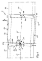
- the tubular elements are in particular designed as prefabricated concrete parts which are joined to one another on the end faces in order to form a channel 1 in this row. Such a channel 1 is laid in the ground and exposed to uneven subsidence along its bottom side (settlement area).
- the tubular element 21 comprises on one end face a sleeve 3 formed by a circumferential projecting sleeve edge 30.
- the sleeve while leaving a gap 9, receives a plug or tip end edge 4 which is circumferentially formed on the opposite end face of the adjacent tubular element 22 .
- a seal 8 in the form of a circumferential ring is applied to the tip end edge 4.
- the seal 8 consists of an elastic plastic and closes the gap 9 forming a peripheral joint between the sleeve edge 30 and the tip end edge 4, the joint being sealed against liquid or gases.
- an articulated connection in the form of an articulated toothing is formed between two adjacent tubular elements 21, 22 or 22, 23, with interlocking toothing elements in the longitudinal (axial) direction of the tubular elements, with which a defined and defined rotation or tilting of adjacent tubular elements is reached.
- a recess 71, 72 is formed in the sleeve edge 30.
- the center plane 51 halves the diameter of the tubular elements in the direction of the settlement movement.
- brackets 61, 62 in the form of noses or protruding parts are arranged on the outside.
- the brackets 61, 62 are arranged and designed such that they engage in the form of a tooth in the associated recess 71 and 72, respectively.
- the two toothed connections 61/71 and 62/72 form a toothed joint 67 with an imaginary main axis 5.
- tubular elements 21, 22 and 22, 23, which are joined together, are rotatably or tiltably mounted.
- the tubular element 22 is at an angle of e.g. w ⁇ 3 ° tilted.
- the insertion length e of the tip end edge 4 is greater than the insertion length g of the brackets 61 and 62. This ensures that there is also an area in the area of the brackets 61, 62 between the tip end edge 4 and the console end face remains through which the seal 8 can be performed.
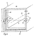
- an (imaginary) circumferential sealing area 80 is shown in FIG. 2 on the sleeve edge associated with the spigot end. This sealing area 80 corresponds to the arrangement of the seal 8 in the case of assembled pipe elements in the unbent state.
- a particularly useful and advantageous embodiment of the invention is that the sleeve edge 30 in The area of the recesses 71, 72 protrudes on the end face, where it slopes away to the upper side 24 and the lower side 25 of the tubular element 2 with inclined surfaces 26.
- the protruding sleeve edge 30 with the recesses 71, 72 ensures that the width g of the console teeth 61, 62 is substantially equal to the depth f of the recesses 71, 72.
- the tubular elements are thus in the area of the recess, while the sloping surfaces create a growing gap towards the edges, which closes when there are bends.
- the inclined surface 26 can also be used as a defined system for a peripheral edge 41 formed below the tip end edge 4.
- sealing surfaces 31 of the sleeve edge with a curvature which is determined by a radius R about a central joint axis 5 of the toothed joint connections 61/71 and 62/72.
- a substantially constant pressure for the seal 8 is achieved.
- a circumferential sleeve bottom edge 32 is formed within the sleeve 3.
- This bottom edge 32 is raised in the area of the central hinge axis 5 or in the area of the recesses 71, 72, while it slopes back with inclined surfaces 33 to the top 24 and the bottom 25 of the tubular element 2.
- the elevation 34 can be provided in order to form a defined contact for the end face of the tip end edge 4 of the adjacent tubular element, in particular as a stop for the tubular elements during assembly.
- the inclined surface 33 can also be used instead of the inclined surface 26 in order to provide an end face contact with maximum bending or tilting between two pipe elements.
- these toothing elements are shaped such that a tilting or rotating movement is possible to the desired extent.
- a sufficient clearance of the console tooth in the recess is to be provided, or - which is more expedient - the support surfaces 63 are rounded on the brackets 61, 62.
- the bearing surfaces 73 of the recess 71, 72 can also be provided with correspondingly concave bends or curvatures. Due to the clearance between brackets 61/62 and recesses 71/72 required for assembly, the bracket lies against the upper or lower support depending on the direction of the transverse forces. The tilt axis then coincides with the connecting line between the loaded bearing surfaces.
- tubular elements can also have other cross sections, in particular circular cross sections.
- pipe elements as channel segments can also be curved or bent as such.
Landscapes
- Engineering & Computer Science (AREA)
- General Engineering & Computer Science (AREA)
- Mechanical Engineering (AREA)
- Health & Medical Sciences (AREA)
- Life Sciences & Earth Sciences (AREA)
- Hydrology & Water Resources (AREA)
- Public Health (AREA)
- Water Supply & Treatment (AREA)
- Joints Allowing Movement (AREA)
- Supports For Pipes And Cables (AREA)
- Duct Arrangements (AREA)
- Rigid Pipes And Flexible Pipes (AREA)
- Vaporization, Distillation, Condensation, Sublimation, And Cold Traps (AREA)
Claims (5)
- Elément tubulaire (2), destiné à réaliser une gaine (1) constituée de plusieurs de ces éléments (21, 22, 23), dans lequel une extrémité à emboîtement (30) est disposée sur un front de l'élément, une extrémité à bout mâle (4), comportant une garniture d'étanchéité (8) élastique sur tout le pourtour de l'élément, étant disposée sur l'autre front, caractérisé en ce que l'extrémité à emboîtement (30) et l'extrémité à bout mâle (4) sont pourvues d'éléments d'engrènement (61,62;71,72), qui engrènent les uns dans les autres dans la direction longitudinale de l'élément tubulaire (2), de façon à former une articulation en engrènement (67), avec une zone de basculement parfaitement définie pour deux éléments tubulaires aboutés (21, 22 ou 22, 23).
- Elément tubulaire selon la revendication 1, caractérisé en ce qu'une paire de consoles opposées (61, 62) sont disposées à l'extérieur contre l'extrémité à bout mâle (4), l'extrémité à bout mâle (4) étant en saillie, dans le sens longitudinal de l'élément tubulaire (2), par rapport aux consoles (61, 62), et qu'une paire d'évidements (71, 72) sont formés dans l'extrémité à emboîtement (30), les deux consoles (61, 62) d'un élément tubulaire (22) et les deux évidements de l'élément tubulaire immédiatement voisin (21) formant l'articulation à engrènement (67).
- Elément tubulaire selon la revendication 2, caractérisé en ce que les surfaces d'appui (63) des consoles (61, 62) sont arrondies.
- Elément tubulaire selon l'une des revendications 1 à 3, caractérisé en ce que l'extrémité à emboîtement (30), quand augmente sa distance à un axe d'articulation moyen (5), recule dans la direction de l'axe longitudinal (50) de l'élément tubulaire (2).
- Elément tubulaire selon l'une des revendications 1 à 4, caractérisé en ce que les surfaces d'étanchéité (31) de l'extrémité à emboîtement (30) présentent une courbure de rayon (R) autour d'un axe d'articulation (5).
Priority Applications (1)
| Application Number | Priority Date | Filing Date | Title |
|---|---|---|---|
| AT90250233T ATE86366T1 (de) | 1989-09-13 | 1990-09-12 | Rohrelement zum aufbau eines kanals. |
Applications Claiming Priority (2)
| Application Number | Priority Date | Filing Date | Title |
|---|---|---|---|
| DE3930615A DE3930615A1 (de) | 1989-09-13 | 1989-09-13 | Rohrelement zum aufbau eines kanals |
| DE3930615 | 1989-09-13 |
Publications (2)
| Publication Number | Publication Date |
|---|---|
| EP0417876A1 EP0417876A1 (fr) | 1991-03-20 |
| EP0417876B1 true EP0417876B1 (fr) | 1993-03-03 |
Family
ID=6389363
Family Applications (1)
| Application Number | Title | Priority Date | Filing Date |
|---|---|---|---|
| EP90250233A Expired - Lifetime EP0417876B1 (fr) | 1989-09-13 | 1990-09-12 | Elément de tuyau pour assembler un canal |
Country Status (5)
| Country | Link |
|---|---|
| EP (1) | EP0417876B1 (fr) |
| AT (1) | ATE86366T1 (fr) |
| DD (1) | DD300043A7 (fr) |
| DE (2) | DE3930615A1 (fr) |
| DK (1) | DK0417876T3 (fr) |
Families Citing this family (2)
| Publication number | Priority date | Publication date | Assignee | Title |
|---|---|---|---|---|
| DE10143306C1 (de) * | 2001-09-04 | 2003-02-06 | Harald Bayerl | Winkelrohr |
| DE102008039820A1 (de) * | 2008-08-22 | 2010-03-04 | Zerna Ingenieure Gmbh | Vortriebsrohr und Aufsatz für ein Vortriebsrohr |
Family Cites Families (6)
| Publication number | Priority date | Publication date | Assignee | Title |
|---|---|---|---|---|
| US2475834A (en) * | 1945-05-05 | 1949-07-12 | Solar Aircraft Co | Flexible pipe joint |
| FR2292918A1 (fr) * | 1974-11-27 | 1976-06-25 | Bresso Claude | Ouvrage forme de caissons en beton juxtaposes |
| DE3019623A1 (de) * | 1980-05-22 | 1981-11-26 | Dipl.-Ing. Wilhelm Markgraf KG Bauunternehmung, 8580 Bayreuth | Rohrverbindung |
| DE3310264A1 (de) * | 1983-03-22 | 1984-09-27 | Phoenix Ag, 2100 Hamburg | Gummiring zum abdichten eines muffenrohrspaltes |
| DE3526704A1 (de) * | 1985-07-25 | 1987-02-05 | Thyssen Plastik Anger Kg | Gelenkelement fuer rohre oder dergl. |
| DE3606420A1 (de) * | 1986-02-27 | 1987-09-03 | Thyssen Plastik Anger Kg | Kippgelenkelement |
-
1989
- 1989-09-13 DE DE3930615A patent/DE3930615A1/de not_active Withdrawn
-
1990
- 1990-09-12 DE DE9090250233T patent/DE59000966D1/de not_active Expired - Fee Related
- 1990-09-12 DK DK90250233.5T patent/DK0417876T3/da active
- 1990-09-12 AT AT90250233T patent/ATE86366T1/de not_active IP Right Cessation
- 1990-09-12 EP EP90250233A patent/EP0417876B1/fr not_active Expired - Lifetime
- 1990-09-13 DD DD343987A patent/DD300043A7/de unknown
Also Published As
| Publication number | Publication date |
|---|---|
| DE59000966D1 (de) | 1993-04-08 |
| DD300043A7 (de) | 1992-05-21 |
| EP0417876A1 (fr) | 1991-03-20 |
| DK0417876T3 (da) | 1993-07-12 |
| ATE86366T1 (de) | 1993-03-15 |
| DE3930615A1 (de) | 1991-03-21 |
Similar Documents
| Publication | Publication Date | Title |
|---|---|---|
| DE69929615T2 (de) | Abgedichtete kupplung mit verstellbarer geometrie | |
| EP3769019B1 (fr) | Ensemble d'entraînement | |
| EP0663047B1 (fr) | Systeme tubulaire pour constructions tubulaires | |
| EP0356628B1 (fr) | Dispositif d'obturation de joints de dilatation et de tassement | |
| EP0141276A2 (fr) | Raccord à douille verrouillée pour tuyaux, notamment pour tuyaux à manchon | |
| DE2455918A1 (de) | Rohrkupplung | |
| DE7931882U1 (de) | Verriegelte muffenverbindung | |
| AT505609B1 (de) | Fördervorrichtung | |
| EP0101544B1 (fr) | Dispositif pour accoupler une barre enrouleuse avec un arbre d'entraînement | |
| EP0417876B1 (fr) | Elément de tuyau pour assembler un canal | |
| DE4409022A1 (de) | Gelenkrohr | |
| DE9218100U1 (de) | Biegsamer Gliederschlauch zur Führung und zum Schutz von medizinischen, insbesondere zahnmedizinischen Medienleitungen | |
| DE1800923C3 (de) | Zug- und Schubsicherung für Schraubmuffen-Verbindungen von Rohren | |
| EP1072918A2 (fr) | Elément de connecteur pour connexion optique | |
| EP0096198A2 (fr) | Tronçon articulé pour conduite | |
| DE3607231A1 (de) | Schubgesicherte steckmuffenverbindung | |
| DE3337714A1 (de) | Wellenkupplung | |
| DE2553388A1 (de) | Vorgefertigter kanalisationsschacht mit rohranschlusstuecken | |
| DD231489A1 (de) | Steuerbares biegsames rohr, insbesondere fuer ein flexibles endoskop | |
| DE19711362C2 (de) | Kaminrohr-Formstück mit seitlicher Rohrabzweigung | |
| DE2748512A1 (de) | Abzweigarmatur fuer rohre, insbesondere fuer bewaesserungsanlagen | |
| WO2021175890A1 (fr) | Système de raccordement pour un système de transfert de fluide fermé | |
| DE3422855C1 (de) | Gehäuse für eine abwinkelbare Gelenkverbindung zwischen zwei Wellenenden | |
| DE2804017A1 (de) | Vorrichtung zum verbinden zweier rohrenden | |
| DE2232522A1 (de) | Universaldoppelgelenk |
Legal Events
| Date | Code | Title | Description |
|---|---|---|---|
| PUAI | Public reference made under article 153(3) epc to a published international application that has entered the european phase |
Free format text: ORIGINAL CODE: 0009012 |
|
| 17P | Request for examination filed |
Effective date: 19901228 |
|
| AK | Designated contracting states |
Kind code of ref document: A1 Designated state(s): AT BE CH DE DK FR IT LI NL SE |
|
| 17Q | First examination report despatched |
Effective date: 19920422 |
|
| GRAA | (expected) grant |
Free format text: ORIGINAL CODE: 0009210 |
|
| AK | Designated contracting states |
Kind code of ref document: B1 Designated state(s): AT BE CH DE DK FR IT LI NL SE |
|
| PG25 | Lapsed in a contracting state [announced via postgrant information from national office to epo] |
Ref country code: IT Free format text: LAPSE BECAUSE OF FAILURE TO SUBMIT A TRANSLATION OF THE DESCRIPTION OR TO PAY THE FEE WITHIN THE PRE;WARNING: LAPSES OF ITALIAN PATENTS WITH EFFECTIVE DATE BEFORE 2007 MAY HAVE OCCURRED AT ANY TIME BEFORE 2007. THE CORRECT EFFECTIVE DATE MAY BE DIFFERENT FROM THE ONE RECORDED.SCRIBED TIME-LIMIT Effective date: 19930303 Ref country code: BE Effective date: 19930303 Ref country code: SE Effective date: 19930303 |
|
| REF | Corresponds to: |
Ref document number: 86366 Country of ref document: AT Date of ref document: 19930315 Kind code of ref document: T |
|
| REF | Corresponds to: |
Ref document number: 59000966 Country of ref document: DE Date of ref document: 19930408 |
|
| ET | Fr: translation filed | ||
| REG | Reference to a national code |
Ref country code: DK Ref legal event code: T3 |
|
| PG25 | Lapsed in a contracting state [announced via postgrant information from national office to epo] |
Ref country code: AT Effective date: 19930912 |
|
| PG25 | Lapsed in a contracting state [announced via postgrant information from national office to epo] |
Ref country code: CH Effective date: 19930930 Ref country code: LI Effective date: 19930930 |
|
| PGFP | Annual fee paid to national office [announced via postgrant information from national office to epo] |
Ref country code: NL Payment date: 19930930 Year of fee payment: 4 |
|
| PLBE | No opposition filed within time limit |
Free format text: ORIGINAL CODE: 0009261 |
|
| STAA | Information on the status of an ep patent application or granted ep patent |
Free format text: STATUS: NO OPPOSITION FILED WITHIN TIME LIMIT |
|
| 26N | No opposition filed | ||
| REG | Reference to a national code |
Ref country code: CH Ref legal event code: PL |
|
| PGFP | Annual fee paid to national office [announced via postgrant information from national office to epo] |
Ref country code: FR Payment date: 19940913 Year of fee payment: 5 |
|
| PGFP | Annual fee paid to national office [announced via postgrant information from national office to epo] |
Ref country code: DK Payment date: 19940916 Year of fee payment: 5 |
|
| PG25 | Lapsed in a contracting state [announced via postgrant information from national office to epo] |
Ref country code: NL Effective date: 19950401 |
|
| NLV4 | Nl: lapsed or anulled due to non-payment of the annual fee | ||
| PG25 | Lapsed in a contracting state [announced via postgrant information from national office to epo] |
Ref country code: DK Effective date: 19950912 |
|
| REG | Reference to a national code |
Ref country code: DK Ref legal event code: EBP |
|
| PG25 | Lapsed in a contracting state [announced via postgrant information from national office to epo] |
Ref country code: FR Effective date: 19960531 |
|
| REG | Reference to a national code |
Ref country code: FR Ref legal event code: ST |
|
| PGFP | Annual fee paid to national office [announced via postgrant information from national office to epo] |
Ref country code: DE Payment date: 20011218 Year of fee payment: 12 |
|
| PG25 | Lapsed in a contracting state [announced via postgrant information from national office to epo] |
Ref country code: DE Free format text: LAPSE BECAUSE OF NON-PAYMENT OF DUE FEES Effective date: 20030401 |