EP0417877A1 - Vanne à tiroir de cisaillement - Google Patents
Vanne à tiroir de cisaillement Download PDFInfo
- Publication number
- EP0417877A1 EP0417877A1 EP90300195A EP90300195A EP0417877A1 EP 0417877 A1 EP0417877 A1 EP 0417877A1 EP 90300195 A EP90300195 A EP 90300195A EP 90300195 A EP90300195 A EP 90300195A EP 0417877 A1 EP0417877 A1 EP 0417877A1
- Authority
- EP
- European Patent Office
- Prior art keywords
- gate
- sleeve
- rings
- shearing
- insert
- Prior art date
- Legal status (The legal status is an assumption and is not a legal conclusion. Google has not performed a legal analysis and makes no representation as to the accuracy of the status listed.)
- Withdrawn
Links
- 238000010008 shearing Methods 0.000 title claims abstract description 47
- 239000000463 material Substances 0.000 claims abstract description 21
- 230000006835 compression Effects 0.000 claims abstract description 15
- 238000007906 compression Methods 0.000 claims abstract description 15
- 230000036316 preload Effects 0.000 claims abstract description 8
- UONOETXJSWQNOL-UHFFFAOYSA-N tungsten carbide Chemical compound [W+]#[C-] UONOETXJSWQNOL-UHFFFAOYSA-N 0.000 claims abstract description 8
- 230000006378 damage Effects 0.000 claims abstract description 7
- 238000007789 sealing Methods 0.000 claims description 6
- 238000010438 heat treatment Methods 0.000 claims 1
- 239000007787 solid Substances 0.000 description 3
- PXHVJJICTQNCMI-UHFFFAOYSA-N Nickel Chemical compound [Ni] PXHVJJICTQNCMI-UHFFFAOYSA-N 0.000 description 2
- 229910045601 alloy Inorganic materials 0.000 description 2
- 239000000956 alloy Substances 0.000 description 2
- 238000003780 insertion Methods 0.000 description 2
- 230000037431 insertion Effects 0.000 description 2
- 229910052751 metal Inorganic materials 0.000 description 2
- 239000002184 metal Substances 0.000 description 2
- QYEXBYZXHDUPRC-UHFFFAOYSA-N B#[Ti]#B Chemical compound B#[Ti]#B QYEXBYZXHDUPRC-UHFFFAOYSA-N 0.000 description 1
- 229910000531 Co alloy Inorganic materials 0.000 description 1
- 229910033181 TiB2 Inorganic materials 0.000 description 1
- 238000005299 abrasion Methods 0.000 description 1
- 229910052782 aluminium Inorganic materials 0.000 description 1
- XAGFODPZIPBFFR-UHFFFAOYSA-N aluminium Chemical compound [Al] XAGFODPZIPBFFR-UHFFFAOYSA-N 0.000 description 1
- 239000000919 ceramic Substances 0.000 description 1
- 229910010293 ceramic material Inorganic materials 0.000 description 1
- 238000001816 cooling Methods 0.000 description 1
- 230000000694 effects Effects 0.000 description 1
- 230000002452 interceptive effect Effects 0.000 description 1
- 238000000034 method Methods 0.000 description 1
- 229910052759 nickel Inorganic materials 0.000 description 1
- 229910052755 nonmetal Inorganic materials 0.000 description 1
- 230000000717 retained effect Effects 0.000 description 1
- 229910010271 silicon carbide Inorganic materials 0.000 description 1
- HBMJWWWQQXIZIP-UHFFFAOYSA-N silicon carbide Chemical compound [Si+]#[C-] HBMJWWWQQXIZIP-UHFFFAOYSA-N 0.000 description 1
- 239000010935 stainless steel Substances 0.000 description 1
- 229910001220 stainless steel Inorganic materials 0.000 description 1
- WFKWXMTUELFFGS-UHFFFAOYSA-N tungsten Chemical compound [W] WFKWXMTUELFFGS-UHFFFAOYSA-N 0.000 description 1
- 239000010937 tungsten Substances 0.000 description 1
- 229910052721 tungsten Inorganic materials 0.000 description 1
Images


Classifications
-
- F—MECHANICAL ENGINEERING; LIGHTING; HEATING; WEAPONS; BLASTING
- F16—ENGINEERING ELEMENTS AND UNITS; GENERAL MEASURES FOR PRODUCING AND MAINTAINING EFFECTIVE FUNCTIONING OF MACHINES OR INSTALLATIONS; THERMAL INSULATION IN GENERAL
- F16K—VALVES; TAPS; COCKS; ACTUATING-FLOATS; DEVICES FOR VENTING OR AERATING
- F16K3/00—Gate valves or sliding valves, i.e. cut-off apparatus with closing members having a sliding movement along the seat for opening and closing
- F16K3/30—Details
- F16K3/314—Forms or constructions of slides; Attachment of the slide to the spindle
-
- E—FIXED CONSTRUCTIONS
- E21—EARTH OR ROCK DRILLING; MINING
- E21B—EARTH OR ROCK DRILLING; OBTAINING OIL, GAS, WATER, SOLUBLE OR MELTABLE MATERIALS OR A SLURRY OF MINERALS FROM WELLS
- E21B29/00—Cutting or destroying pipes, packers, plugs or wire lines, located in boreholes or wells, e.g. cutting of damaged pipes, of windows; Deforming of pipes in boreholes or wells; Reconditioning of well casings while in the ground
- E21B29/04—Cutting of wire lines or the like
-
- E—FIXED CONSTRUCTIONS
- E21—EARTH OR ROCK DRILLING; MINING
- E21B—EARTH OR ROCK DRILLING; OBTAINING OIL, GAS, WATER, SOLUBLE OR MELTABLE MATERIALS OR A SLURRY OF MINERALS FROM WELLS
- E21B29/00—Cutting or destroying pipes, packers, plugs or wire lines, located in boreholes or wells, e.g. cutting of damaged pipes, of windows; Deforming of pipes in boreholes or wells; Reconditioning of well casings while in the ground
- E21B29/08—Cutting or deforming pipes to control fluid flow
-
- F—MECHANICAL ENGINEERING; LIGHTING; HEATING; WEAPONS; BLASTING
- F16—ENGINEERING ELEMENTS AND UNITS; GENERAL MEASURES FOR PRODUCING AND MAINTAINING EFFECTIVE FUNCTIONING OF MACHINES OR INSTALLATIONS; THERMAL INSULATION IN GENERAL
- F16K—VALVES; TAPS; COCKS; ACTUATING-FLOATS; DEVICES FOR VENTING OR AERATING
- F16K3/00—Gate valves or sliding valves, i.e. cut-off apparatus with closing members having a sliding movement along the seat for opening and closing
- F16K3/02—Gate valves or sliding valves, i.e. cut-off apparatus with closing members having a sliding movement along the seat for opening and closing with flat sealing faces; Packings therefor
- F16K3/0263—Gate valves or sliding valves, i.e. cut-off apparatus with closing members having a sliding movement along the seat for opening and closing with flat sealing faces; Packings therefor using particular material or covering means
-
- F—MECHANICAL ENGINEERING; LIGHTING; HEATING; WEAPONS; BLASTING
- F16—ENGINEERING ELEMENTS AND UNITS; GENERAL MEASURES FOR PRODUCING AND MAINTAINING EFFECTIVE FUNCTIONING OF MACHINES OR INSTALLATIONS; THERMAL INSULATION IN GENERAL
- F16K—VALVES; TAPS; COCKS; ACTUATING-FLOATS; DEVICES FOR VENTING OR AERATING
- F16K31/00—Actuating devices; Operating means; Releasing devices
- F16K31/12—Actuating devices; Operating means; Releasing devices actuated by fluid
- F16K31/122—Actuating devices; Operating means; Releasing devices actuated by fluid the fluid acting on a piston
- F16K31/1221—Actuating devices; Operating means; Releasing devices actuated by fluid the fluid acting on a piston one side of the piston being spring-loaded
-
- Y—GENERAL TAGGING OF NEW TECHNOLOGICAL DEVELOPMENTS; GENERAL TAGGING OF CROSS-SECTIONAL TECHNOLOGIES SPANNING OVER SEVERAL SECTIONS OF THE IPC; TECHNICAL SUBJECTS COVERED BY FORMER USPC CROSS-REFERENCE ART COLLECTIONS [XRACs] AND DIGESTS
- Y10—TECHNICAL SUBJECTS COVERED BY FORMER USPC
- Y10T—TECHNICAL SUBJECTS COVERED BY FORMER US CLASSIFICATION
- Y10T83/00—Cutting
- Y10T83/929—Tool or tool with support
- Y10T83/9411—Cutting couple type
- Y10T83/9447—Shear type
Definitions
- the present invention relates to a gate valve capable of shearing a wire line or small pipe extending through its bore.
- Gate valves have been used for shearing through wire lines and small tubular members but difficulties have been encountered after a shearing has taken place with prior shearing gate valves. Often the problem is that the valve which has accomplished the shearing no longer has a satisfactory seal. An additional problem is that prior shearing gate valves have also damaged the shearing edges during their initial shearing operation and had to be repaired prior to being placed in service thereafter.
- U. S. Patent Nos. 4,519,575 and 4,612,983 disclose typical prior art gate valves adapted for shearing a wire line extending through the valve passages and the gate.
- Patent No. 4,519,575 discloses a gate valve for shearing a wire line on closing and the gate valve includes a special actuator which adds closing force during the last or shearing portion of the stroke.
- Patent No. 4,612,983 discloses a gate valve having a pair of gates in which the lower gate closes and shears the wire line and then the upper gate closes and seals against the upper valve seat.
- U. S. Patent No. 4,281,819 discloses a balanced stem gate valve in which the sealing surfaces are hard, friction resistant sealing surfaces and suggests valve seats of metal or non-metal seat material concentrically disposed interiorly of seat retainers and sealed with sealing rings.
- Back-up seat rings are provided and are of a hard material such as tungsten carbide.
- U. S. Patent Nos. 4,081,027 and 4,341,264 disclose ram type blowout preventers having shearing type of rams in which the leading edge of the shearing blade of each ram is provided with a hardened shearing surface.
- the rams are hardfaced with a layer of nickel-based alloys, cobalt-based alloy and tungsten-based alloys to allow the shearing of a drill pipe.
- the 4,341,264 patent suggest the use of a hardened material insert on the leading edges of the shear blades so that it is replaceable and the ram blade can be repaired after any damage during shearing.
- U. S. Patent No. 4,425,699 discloses the method of connecting a mechanical seal ring of hard metal or ceramic to a supporting ring made of aluminum or stainless steel which includes the pressing of the two rings against each other with such force that the supporting ring yields to provide a permanent engagement between the rings.
- U. S. Patent No. 4,337,920 discloses a valve or choke for use in high temperature and extremely abrasive service which includes the use of a sleeve of abrasion resistant material, such as cemented tungsten carbide, silicon carbide, titanium diboride, ceramic material or other material.
- a sleeve of abrasion resistant material such as cemented tungsten carbide, silicon carbide, titanium diboride, ceramic material or other material.
- the sleeve is supported by springs to prevent its damage from vibrations and to insulate it from the effects of differential expansion.
- the present invention relates to a shear type of gate valve in which both the gate and the seat rings include inserts of hard material to assist in the shearing of wire lines or tubular members extending through the valve when it is to be closed.
- the hard material such as tungsten carbide
- the recess for each of the rings and the size of the ring are preselected so that the rings, once positioned in their recesses, are maintained in compression at all times.
- the preferred rings are made of tungsten carbide.
- An object of the present invention is to provide an improved shearing type of gate valve in which the gate has a seal which is not damaged by the shearing action of the gate.
- Another object is to provide an improved shearing type of gate valve in which the valve may be retained in service after multiple shearing closures of the gate.
- a further object is to provide an improved shearing type of gate valve in which a brittle hard material is used without having the brittle material damaged by the shearing action of the valve.
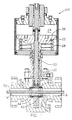
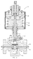
- Valve 10 shown in FIGURES 1 and 2, discloses the improved shearing type of gate valve of the present invention.
- Valve 10 includes body 12 having an inlet 14, an outlet 16 with valve chamber 18 between the inner ends of inlet 14 and outlet 16 and bonnet 20 which is secured to body 12 around the opening of chamber 18 into body 12.
- Bonnet 20 supports actuator 22 which is shown as a simply pneumatic actuator having piston chamber 24 with piston 26 slidable therein and spring 28 urging piston 26 upward as shown.
- Connecting rod 30 extends from piston 26 through bonnet 20 into engagement with gate 32 for moving gate 32 within chamber 18 to open or close flow therethrough between inlet 14 and outlet 16.
- Gate 32 is positioned between seat rings 34 and 36 which are positioned in recesses 38 and 40 of body 12, respectively, which surround the inner ends of inlet 14 and outlet 16 in chamber 18. Opening 42 which extends through gate 32 is lined with hardened sleeve 44 which coacts with hardened insert rings 46 and 48 positioned in seat rings 34 and 36 in the shearing action of the gate 32 during its closing movement when there is a wire line 50 or a tubular member (not shown) extending through valve 10.
- the shearing of wire line 50 is shown in FIGURE 2. Wire line 50 has been sheared in two places by the action of sleeve 44 on the seat ring insert rings 46 and 48.
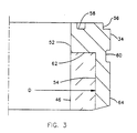
- Ring 34 and 36 are identical and seat ring 34 is illustrated in FIGURE 3 to explain the details of structure of rings 34 and 36.
- Ring 34 is annular in shape having bore 52, inner recess 54 on one end, projection 56 on the opposite end with seal ring groove 58 in its face for receiving a suitable seal ring; and external groove 60 in outer surface 64.
- Projection 56 is sized to fit tightly within recess 38 of body 12.
- Inner recess 54 is sized to have an inner diameter D which is smaller than the diameter of insert ring 46 prior to assembly. When assembled, insert ring 46 fits within inner recess 54 and abuts shoulder 62 of inner recess 54.
- Insert ring 48 is identical to insert ring 46.
- the external diameter of insert ring 46 and the internal diameter D of recess 54 are selected to have an interference fit.
- the amount of interference is selected to provide a preselected amount of compression on insert ring 46 after it has been assembled within recess 54.
- the amount of such compression is to be sufficient to maintain insert ring 46 in compression during all operations including shearing of wire line 50 or a tubular members (not shown) which may be extending through valve 10 when it is to be closed.
- the reason for placing insert ring 46 in compression is that it is made of a brittle material, such as tungsten carbide or other suitable hard material, which has little strength in tension.
- insert ring 46 By preloading insert ring 46 with sufficient compression to ensure that it is never placed in tension, insert ring 46 is never exposed to conditions which would result in its failure, such as a chipping of its shearing edges. It is suggested that assembly of insert ring 46 with seat ring 34 be accomplished with seat ring 34 heated sufficiently to allow insertion of insert ring 46 without undue loading of either component during assembly. After seat ring 34 has cooled with insert ring 46 positioned in its recess 54, seat ring 34 will shrink sufficiently to provide the desired compression preload of insert ring 46. The compressive preload on insert rings f46 and 48 is sufficient to ensure that there is no relative movement of the insert rings and seat rings 34 and 36 during operation of the gate valve. Groove 60 is provided to allow the seat ring to be removed from the body by prying with a screw driver or similar tool.
- gate 32 is a generally flat elongated plate and includes means 66 for suitable connection to connecting rod 30 and opening 42 in which sleeve 44 of hardened material is positioned.
- Sleeve 44 is made of the same or similar material to the material of insert ring 46.
- the inner diameter of opening 42 is sized with respect to the external diameter of sleeve 44 so that on insertion of sleeve 44 therein (by a shrink fit), it is preloaded with sufficient compression preloading to ensure that it will not be loaded in tension during its use. This is done, preferably in the same manner as the assembly of insert ring 46 within seat ring 34.
- Gate 32 is heated sufficiently to allow sleeve 44 to be readily inserted into opening 42.
- the diameter of opening 42 is sufficiently smaller after cooling than the outer diameter of sleeve 44 to provide the desired preselected compression preload on sleeve 44. This will ensure that during all operations of gate 32, sleeve 44 will be under compression and will perform its sealing and shearing functions without destruction, chipping or other damage thereto.
- the compressive preload on sleeve 44 is sufficient to ensure that there is no relative movement between sleeve 44 and gate 32 during operation of gate valve 10.
- the valve was tested to full rated working pressure of 15,000 psi after each shearing with no detectable leakage.
- the improved design of the shearing gate valve of the present invention provides a gate valve which can shear a wire line or other tubular member extending therethrough without damage to the hardened inserts 46 and 48 and the hardened sleeve 44 or in any way interfering with the sealing of the gate and the seat rings.
- This allows the valve 10 to be used without repair or replacement through many cycles of closing and shearing whereas shearing gate valves of the prior art could only be expected to accomplish a single shearing and even following such single shearing may have been damaged sufficiently to provide an imperfect seal.
Landscapes
- Engineering & Computer Science (AREA)
- General Engineering & Computer Science (AREA)
- Mining & Mineral Resources (AREA)
- Life Sciences & Earth Sciences (AREA)
- Geology (AREA)
- Mechanical Engineering (AREA)
- Fluid Mechanics (AREA)
- Environmental & Geological Engineering (AREA)
- Physics & Mathematics (AREA)
- General Life Sciences & Earth Sciences (AREA)
- Geochemistry & Mineralogy (AREA)
- Sliding Valves (AREA)
- Details Of Valves (AREA)
- Shearing Machines (AREA)
Applications Claiming Priority (2)
| Application Number | Priority Date | Filing Date | Title |
|---|---|---|---|
| US07/384,823 US4911410A (en) | 1989-07-21 | 1989-07-21 | Shearing gate valve |
| US384823 | 1989-07-21 |
Publications (1)
| Publication Number | Publication Date |
|---|---|
| EP0417877A1 true EP0417877A1 (fr) | 1991-03-20 |
Family
ID=23518909
Family Applications (1)
| Application Number | Title | Priority Date | Filing Date |
|---|---|---|---|
| EP90300195A Withdrawn EP0417877A1 (fr) | 1989-07-21 | 1990-01-08 | Vanne à tiroir de cisaillement |
Country Status (4)
| Country | Link |
|---|---|
| US (1) | US4911410A (fr) |
| EP (1) | EP0417877A1 (fr) |
| JP (1) | JPH0360910A (fr) |
| CA (1) | CA2007557C (fr) |
Cited By (4)
| Publication number | Priority date | Publication date | Assignee | Title |
|---|---|---|---|---|
| US6454015B1 (en) * | 1999-07-15 | 2002-09-24 | Abb Vetco Gray Inc. | Shearing gate valve |
| RU2241111C1 (ru) * | 2003-05-26 | 2004-11-27 | Абрамов Александр Федорович | Герметизирующее устройство |
| CN103244693A (zh) * | 2012-08-13 | 2013-08-14 | 广西鱼峰水泥股份有限公司 | 防磨排气阀 |
| US9249888B2 (en) | 2014-01-17 | 2016-02-02 | Ge Oil & Gas Pressure Control Lp | Non-welded hardface gate and seats |
Families Citing this family (32)
| Publication number | Priority date | Publication date | Assignee | Title |
|---|---|---|---|---|
| EP0492399A3 (en) * | 1990-12-20 | 1993-03-10 | Abbott Laboratories | A packaging system for a sterilizable calibratable medical device |
| US5097859A (en) * | 1990-12-20 | 1992-03-24 | Abbott Laboratories | Shut-off valve usable in an improved packaging system for a sterilizable calibratable medical device |
| US5370362A (en) * | 1993-10-15 | 1994-12-06 | Abb Vetco Gray Inc. | Gate valve |
| US5501424A (en) * | 1994-02-09 | 1996-03-26 | Fmc Corporation | Wire cutting insert for gate valve |
| US5803431A (en) * | 1995-08-31 | 1998-09-08 | Cooper Cameron Corporation | Shearing gate valve |
| GB2360052B (en) | 2000-03-09 | 2002-04-24 | Fmc Corp | Data line deployment in hydrocarbon wells |
| US7703739B2 (en) * | 2004-11-01 | 2010-04-27 | Hydril Usa Manufacturing Llc | Ram BOP shear device |
| US7234530B2 (en) * | 2004-11-01 | 2007-06-26 | Hydril Company Lp | Ram BOP shear device |
| US7243713B2 (en) * | 2004-11-29 | 2007-07-17 | National-Oilwell Dht, L.P. | Shear/seal ram assembly for a ram-type blowout prevention system |
| US7464765B2 (en) * | 2005-08-24 | 2008-12-16 | National-Oilwell Dht, L.P. | Inner guide seal assembly and method for a ram type BOP system |
| US8070131B2 (en) * | 2008-10-27 | 2011-12-06 | Vetco Gray Inc. | Recessed cutting edge for wire cutting gate valves |
| US8844898B2 (en) * | 2009-03-31 | 2014-09-30 | National Oilwell Varco, L.P. | Blowout preventer with ram socketing |
| US8567490B2 (en) | 2009-06-19 | 2013-10-29 | National Oilwell Varco, L.P. | Shear seal blowout preventer |
| US8544538B2 (en) | 2010-07-19 | 2013-10-01 | National Oilwell Varco, L.P. | System and method for sealing a wellbore |
| US8540017B2 (en) | 2010-07-19 | 2013-09-24 | National Oilwell Varco, L.P. | Method and system for sealing a wellbore |
| KR20150092371A (ko) | 2011-03-09 | 2015-08-12 | 내셔널 오일웰 바르코 엘.피. | 유정 보어를 밀봉하기 위한 방법 및 장치 |
| US20130119288A1 (en) * | 2011-11-16 | 2013-05-16 | Vetco Gray Inc. | Gate shear valve |
| GB2514305B (en) * | 2012-02-28 | 2017-10-11 | Aker Solutions As | DLC-coated gate valve in petroleum production or water injection |
| US9309737B2 (en) * | 2012-06-08 | 2016-04-12 | Vetco Gray U.K. Limited | Rotational shear valve |
| US9097082B2 (en) | 2012-06-20 | 2015-08-04 | Cameron International Corporation | Multi-barrier seal system |
| US20140061522A1 (en) * | 2012-09-05 | 2014-03-06 | Vetco Gray Inc. | Valve Actuator with Degressive Characteristic Spring |
| US9249643B2 (en) | 2013-03-15 | 2016-02-02 | National Oilwell Varco, L.P. | Blowout preventer with wedge ram assembly and method of using same |
| WO2014144792A2 (fr) * | 2013-03-15 | 2014-09-18 | Fmc Technologies, Inc. | Ensemble robinet-vanne comprenant une vanne de cisaillement |
| US10767784B2 (en) * | 2013-11-27 | 2020-09-08 | Cameron International Corporation | Gate valve with pneumatic system for shearing application |
| US10533667B2 (en) | 2015-04-24 | 2020-01-14 | Cameron International Corporation | Shearing gate valve system |
| US20170191336A1 (en) * | 2015-12-31 | 2017-07-06 | Cameron International Corporation | Closure member including a replaceable insert |
| US10391557B2 (en) | 2016-05-26 | 2019-08-27 | Kennametal Inc. | Cladded articles and applications thereof |
| GB201619693D0 (en) * | 2016-11-22 | 2017-01-04 | Interventek Subsea Eng Ltd | Gate valve |
| NL2019327B1 (en) | 2017-07-24 | 2019-02-12 | Ihc Holland Ie Bv | No Flush Valve |
| US10344757B1 (en) * | 2018-01-19 | 2019-07-09 | Kennametal Inc. | Valve seats and valve assemblies for fluid end applications |
| US11566718B2 (en) | 2018-08-31 | 2023-01-31 | Kennametal Inc. | Valves, valve assemblies and applications thereof |
| US12259064B2 (en) | 2018-11-01 | 2025-03-25 | Oil States Energy Services, L.L.C. | Valve with pressure differential seating |
Citations (4)
| Publication number | Priority date | Publication date | Assignee | Title |
|---|---|---|---|---|
| US4281819A (en) * | 1978-03-23 | 1981-08-04 | Linder Morris B | Balanced stem gate valve |
| US4519575A (en) * | 1984-04-20 | 1985-05-28 | Ava International Corporation | Valves and valve actuators |
| US4612983A (en) * | 1985-10-15 | 1986-09-23 | Gray Tool Company | Shear type gate valve |
| US4651970A (en) * | 1986-07-07 | 1987-03-24 | Joy Manufacturing Company | Valve actuator with auxiliary energy storage means |
Family Cites Families (7)
| Publication number | Priority date | Publication date | Assignee | Title |
|---|---|---|---|---|
| US4086832A (en) * | 1976-02-27 | 1978-05-02 | Efco, Inc. | Apparatus for shearing a workpiece such as a metal bar or the like |
| US4081027A (en) * | 1976-08-23 | 1978-03-28 | The Rucker Company | Shear rams for hydrogen sulfide service |
| SE425224B (sv) * | 1977-11-29 | 1982-09-13 | Flygt Ab | Sett att forbinda tva ringformiga element |
| US4341264A (en) * | 1980-10-15 | 1982-07-27 | Cameron Iron Works, Inc. | Wellhead shearing apparatus |
| US4337920A (en) * | 1980-10-16 | 1982-07-06 | Cameron Iron Works, Inc. | Valve |
| US4572298A (en) * | 1982-11-05 | 1986-02-25 | Hydril Company | Gate valve apparatus and method |
| US4825953A (en) * | 1988-02-01 | 1989-05-02 | Otis Engineering Corporation | Well servicing system |
-
1989
- 1989-07-21 US US07/384,823 patent/US4911410A/en not_active Expired - Lifetime
-
1990
- 1990-01-08 EP EP90300195A patent/EP0417877A1/fr not_active Withdrawn
- 1990-01-11 CA CA002007557A patent/CA2007557C/fr not_active Expired - Fee Related
- 1990-01-24 JP JP2014733A patent/JPH0360910A/ja active Pending
Patent Citations (4)
| Publication number | Priority date | Publication date | Assignee | Title |
|---|---|---|---|---|
| US4281819A (en) * | 1978-03-23 | 1981-08-04 | Linder Morris B | Balanced stem gate valve |
| US4519575A (en) * | 1984-04-20 | 1985-05-28 | Ava International Corporation | Valves and valve actuators |
| US4612983A (en) * | 1985-10-15 | 1986-09-23 | Gray Tool Company | Shear type gate valve |
| US4651970A (en) * | 1986-07-07 | 1987-03-24 | Joy Manufacturing Company | Valve actuator with auxiliary energy storage means |
Cited By (5)
| Publication number | Priority date | Publication date | Assignee | Title |
|---|---|---|---|---|
| US6454015B1 (en) * | 1999-07-15 | 2002-09-24 | Abb Vetco Gray Inc. | Shearing gate valve |
| RU2241111C1 (ru) * | 2003-05-26 | 2004-11-27 | Абрамов Александр Федорович | Герметизирующее устройство |
| CN103244693A (zh) * | 2012-08-13 | 2013-08-14 | 广西鱼峰水泥股份有限公司 | 防磨排气阀 |
| CN103244693B (zh) * | 2012-08-13 | 2016-02-24 | 广西鱼峰水泥股份有限公司 | 防磨排气阀 |
| US9249888B2 (en) | 2014-01-17 | 2016-02-02 | Ge Oil & Gas Pressure Control Lp | Non-welded hardface gate and seats |
Also Published As
| Publication number | Publication date |
|---|---|
| CA2007557C (fr) | 1993-11-02 |
| CA2007557A1 (fr) | 1991-01-21 |
| US4911410A (en) | 1990-03-27 |
| JPH0360910A (ja) | 1991-03-15 |
Similar Documents
| Publication | Publication Date | Title |
|---|---|---|
| EP0417877A1 (fr) | Vanne à tiroir de cisaillement | |
| EP0416719A1 (fr) | Vanne à tiroir de cisaillement | |
| US5803431A (en) | Shearing gate valve | |
| US5529285A (en) | Oilfield valve | |
| EP0397725B1 (fr) | Ensemble ressort et siege pour clapets a bille | |
| US6173770B1 (en) | Shear ram for ram-type blowout preventer | |
| US4081027A (en) | Shear rams for hydrogen sulfide service | |
| US6454015B1 (en) | Shearing gate valve | |
| US4531710A (en) | Expanding gate valve | |
| US7249751B2 (en) | Ball valve with shear bushing and integral bracket for stem blowout protection | |
| US6793198B2 (en) | Banded valve plug head | |
| CA2212620A1 (fr) | Vanne rotative avec acces de biais | |
| US5727775A (en) | Gate valve with dual seal rings on a unitary seat ring | |
| MXPA05009295A (es) | Dispositivo de valvula de control de fluidos. | |
| US4272055A (en) | Single double backseat | |
| US5083582A (en) | Valve with removable insert | |
| CA1221000A (fr) | Organe de calage fusible sur tige de robinet | |
| JPH0735245A (ja) | スライド バルブ | |
| US2694547A (en) | Valve structure | |
| US8166993B2 (en) | Method and systems for using a shim plate for increased strength | |
| AU668792B2 (en) | Blowout preventer with removable packer | |
| US11543036B1 (en) | Isolation knife gate valve | |
| CA1112123A (fr) | Clapet a bille pivotant | |
| US9316322B2 (en) | Split seat shear valve | |
| CA1055005A (fr) | Siege de soupape haute pression |
Legal Events
| Date | Code | Title | Description |
|---|---|---|---|
| PUAI | Public reference made under article 153(3) epc to a published international application that has entered the european phase |
Free format text: ORIGINAL CODE: 0009012 |
|
| AK | Designated contracting states |
Kind code of ref document: A1 Designated state(s): AT DE FR GB NL |
|
| RAP1 | Party data changed (applicant data changed or rights of an application transferred) |
Owner name: COOPER INDUSTRIES INC. |
|
| 17P | Request for examination filed |
Effective date: 19910822 |
|
| 17Q | First examination report despatched |
Effective date: 19921023 |
|
| STAA | Information on the status of an ep patent application or granted ep patent |
Free format text: STATUS: THE APPLICATION HAS BEEN WITHDRAWN |
|
| 18W | Application withdrawn |
Withdrawal date: 19930503 |