EP0417931A1 - Piston avec isolation thermique - Google Patents
Piston avec isolation thermique Download PDFInfo
- Publication number
- EP0417931A1 EP0417931A1 EP90309426A EP90309426A EP0417931A1 EP 0417931 A1 EP0417931 A1 EP 0417931A1 EP 90309426 A EP90309426 A EP 90309426A EP 90309426 A EP90309426 A EP 90309426A EP 0417931 A1 EP0417931 A1 EP 0417931A1
- Authority
- EP
- European Patent Office
- Prior art keywords
- heat
- insulating
- head base
- piston according
- thin film
- Prior art date
- Legal status (The legal status is an assumption and is not a legal conclusion. Google has not performed a legal analysis and makes no representation as to the accuracy of the status listed.)
- Granted
Links
- 230000002093 peripheral effect Effects 0.000 claims abstract description 67
- 239000000919 ceramic Substances 0.000 claims abstract description 35
- 239000010409 thin film Substances 0.000 claims abstract description 33
- 229910010293 ceramic material Inorganic materials 0.000 claims description 13
- 229910052581 Si3N4 Inorganic materials 0.000 claims description 12
- HQVNEWCFYHHQES-UHFFFAOYSA-N silicon nitride Chemical compound N12[Si]34N5[Si]62N3[Si]51N64 HQVNEWCFYHHQES-UHFFFAOYSA-N 0.000 claims description 12
- 239000000463 material Substances 0.000 claims description 8
- 238000005229 chemical vapour deposition Methods 0.000 claims description 6
- HBMJWWWQQXIZIP-UHFFFAOYSA-N silicon carbide Chemical compound [Si+]#[C-] HBMJWWWQQXIZIP-UHFFFAOYSA-N 0.000 claims description 6
- 239000011800 void material Substances 0.000 claims description 5
- 239000000835 fiber Substances 0.000 claims description 3
- 229910000990 Ni alloy Inorganic materials 0.000 claims description 2
- 229910045601 alloy Inorganic materials 0.000 claims description 2
- 239000000956 alloy Substances 0.000 claims description 2
- KZHJGOXRZJKJNY-UHFFFAOYSA-N dioxosilane;oxo(oxoalumanyloxy)alumane Chemical compound O=[Si]=O.O=[Si]=O.O=[Al]O[Al]=O.O=[Al]O[Al]=O.O=[Al]O[Al]=O KZHJGOXRZJKJNY-UHFFFAOYSA-N 0.000 claims description 2
- 229910052863 mullite Inorganic materials 0.000 claims description 2
- 238000010438 heat treatment Methods 0.000 claims 1
- 229910010271 silicon carbide Inorganic materials 0.000 claims 1
- 238000002485 combustion reaction Methods 0.000 description 12
- 238000004880 explosion Methods 0.000 description 7
- 239000011810 insulating material Substances 0.000 description 7
- 239000000567 combustion gas Substances 0.000 description 6
- MCMNRKCIXSYSNV-UHFFFAOYSA-N Zirconium dioxide Chemical compound O=[Zr]=O MCMNRKCIXSYSNV-UHFFFAOYSA-N 0.000 description 4
- 230000004308 accommodation Effects 0.000 description 4
- 229910052751 metal Inorganic materials 0.000 description 4
- 239000002184 metal Substances 0.000 description 4
- 230000037431 insertion Effects 0.000 description 3
- 238000003780 insertion Methods 0.000 description 3
- 238000009413 insulation Methods 0.000 description 3
- 238000005452 bending Methods 0.000 description 2
- 239000011248 coating agent Substances 0.000 description 2
- 238000000576 coating method Methods 0.000 description 2
- 230000007797 corrosion Effects 0.000 description 2
- 238000005260 corrosion Methods 0.000 description 2
- 230000035939 shock Effects 0.000 description 2
- OKTJSMMVPCPJKN-UHFFFAOYSA-N Carbon Chemical compound [C] OKTJSMMVPCPJKN-UHFFFAOYSA-N 0.000 description 1
- RTAQQCXQSZGOHL-UHFFFAOYSA-N Titanium Chemical compound [Ti] RTAQQCXQSZGOHL-UHFFFAOYSA-N 0.000 description 1
- PNEYBMLMFCGWSK-UHFFFAOYSA-N aluminium oxide Inorganic materials [O-2].[O-2].[O-2].[Al+3].[Al+3] PNEYBMLMFCGWSK-UHFFFAOYSA-N 0.000 description 1
- 229910052799 carbon Inorganic materials 0.000 description 1
- 230000015556 catabolic process Effects 0.000 description 1
- 239000002131 composite material Substances 0.000 description 1
- NJLLQSBAHIKGKF-UHFFFAOYSA-N dipotassium dioxido(oxo)titanium Chemical compound [K+].[K+].[O-][Ti]([O-])=O NJLLQSBAHIKGKF-UHFFFAOYSA-N 0.000 description 1
- 239000007789 gas Substances 0.000 description 1
- 239000003779 heat-resistant material Substances 0.000 description 1
- 239000007769 metal material Substances 0.000 description 1
- 238000007789 sealing Methods 0.000 description 1
Images

Classifications
-
- F—MECHANICAL ENGINEERING; LIGHTING; HEATING; WEAPONS; BLASTING
- F02—COMBUSTION ENGINES; HOT-GAS OR COMBUSTION-PRODUCT ENGINE PLANTS
- F02F—CYLINDERS, PISTONS OR CASINGS, FOR COMBUSTION ENGINES; ARRANGEMENTS OF SEALINGS IN COMBUSTION ENGINES
- F02F3/00—Pistons
- F02F3/10—Pistons having surface coverings
- F02F3/12—Pistons having surface coverings on piston heads
-
- F—MECHANICAL ENGINEERING; LIGHTING; HEATING; WEAPONS; BLASTING
- F02—COMBUSTION ENGINES; HOT-GAS OR COMBUSTION-PRODUCT ENGINE PLANTS
- F02F—CYLINDERS, PISTONS OR CASINGS, FOR COMBUSTION ENGINES; ARRANGEMENTS OF SEALINGS IN COMBUSTION ENGINES
- F02F3/00—Pistons
- F02F3/0015—Multi-part pistons
- F02F3/003—Multi-part pistons the parts being connected by casting, brazing, welding or clamping
-
- F—MECHANICAL ENGINEERING; LIGHTING; HEATING; WEAPONS; BLASTING
- F05—INDEXING SCHEMES RELATING TO ENGINES OR PUMPS IN VARIOUS SUBCLASSES OF CLASSES F01-F04
- F05C—INDEXING SCHEME RELATING TO MATERIALS, MATERIAL PROPERTIES OR MATERIAL CHARACTERISTICS FOR MACHINES, ENGINES OR PUMPS OTHER THAN NON-POSITIVE-DISPLACEMENT MACHINES OR ENGINES
- F05C2251/00—Material properties
- F05C2251/04—Thermal properties
- F05C2251/042—Expansivity
-
- F—MECHANICAL ENGINEERING; LIGHTING; HEATING; WEAPONS; BLASTING
- F05—INDEXING SCHEMES RELATING TO ENGINES OR PUMPS IN VARIOUS SUBCLASSES OF CLASSES F01-F04
- F05C—INDEXING SCHEME RELATING TO MATERIALS, MATERIAL PROPERTIES OR MATERIAL CHARACTERISTICS FOR MACHINES, ENGINES OR PUMPS OTHER THAN NON-POSITIVE-DISPLACEMENT MACHINES OR ENGINES
- F05C2251/00—Material properties
- F05C2251/04—Thermal properties
- F05C2251/048—Heat transfer
-
- F—MECHANICAL ENGINEERING; LIGHTING; HEATING; WEAPONS; BLASTING
- F05—INDEXING SCHEMES RELATING TO ENGINES OR PUMPS IN VARIOUS SUBCLASSES OF CLASSES F01-F04
- F05C—INDEXING SCHEME RELATING TO MATERIALS, MATERIAL PROPERTIES OR MATERIAL CHARACTERISTICS FOR MACHINES, ENGINES OR PUMPS OTHER THAN NON-POSITIVE-DISPLACEMENT MACHINES OR ENGINES
- F05C2253/00—Other material characteristics; Treatment of material
- F05C2253/16—Fibres
Definitions
- This invention relates to a heat-insulating piston consisting of a composite structure containing a ceramic member and a heat-insulating member
- This heat-insulating piston comprises a piston head portion 41 having a fitting boss portion 44 at is center and made of a material having a thermal expansion coefficient substantially equal to that of a ceramic material, and a metallic piston skirt portion 42 having a center fitting hole 52 to which the fitting boss portion 44 is fitted at its center.
- the fitting boss portion 44 of the piston head portion 41 and the center fitting hole 52 of the piston skirt portion 42 are fixed to each other by metal flow of a metallic ring 51.
- a heat-insulating buffer material 48 as a heat-insulating gasket is interposed under a push state at the center contact portion between the piston head portion 41 and the piston skirt portion 42.
- a heat-insulating air layer 49 is defined between the piston head portion 41 and the piston skirt portion 42.
- a ceramic thin sheet 45 which is formed to an extremely small thickness in order to reduce thermal capacity, is disposed on the piston head portion 41 through a heat-insulating material 43 in such a manner as to face a combustion chamber.
- a ceramic ring 46 made of the same material as the ceramic thin sheet 45 is fitted to the outer peripheral portion of the latter, and these ceramic thin sheet 45 and ceramic ring 46 are bonded at the contact portion by CVD (Chemical Vapor Deposition) as described in Japanese Patent Laid-Open No. 108171/1989 (U.S. Patent Specification No. 4,848,291), for example.
- CVD Chemical Vapor Deposition
- a step portion 56 is formed on the inner peripheral surface of the ceramic ring 46 and the outer peripheral portion of the piston head portion41 fits to the ceramic ring 46 so as to come into contact with the step portion 56 of the ceramic ring 46.
- a heat-insulating material 43 is sealed into the space defined by the ceramic thin sheet 45, the ceramic ring 46 and the piston head portion 41.
- This heat-insulating material 43 is made of a material such as potassium titanate whiskers, zirconia fibers.
- the structure of the heat-insulating piston disclosed in Japanese Patent Laid-Open No. 302164/1988 is as described above in order to obtain extremely high heat-insulating property, to minimize the thermal capacity of the surface portion of the piston head which is exposed to the combustion gas and reaches high temperature, to improve intake efficiency and cycle efficiency, to eliminate the occurrence of the problems of strength even when a thermal shock is applied, to improve heat resistance, corrosion resistance and deformation resistance, to obtain a stable fitting state and to receive under a preferred state the pressure which acts on the piston head at the time of explosion. Further, it improves the seal function between the piston head and the piston skirt.
- the bond portion between the ceramic thin sheet and the ceramic ring is bonded by chemical vapor deposition or coating, the bond portion does not have the strength sufficient to keep the bonded state against the explosion force at the time of combustion, so that the bond portion between the ceramic thin sheet and the ceramic ring peels or cracks develops.
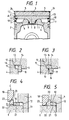
- Fig. 1 shows the structure of the heat-insulating piston in accordance with an embodiment of the present invention.
- This heat-insulating piston comprises primarily a piston skirt member 2, a cylindrical member 4 coming partially into contact with the piston skirt member 2, a head base member 1 fixed to the skirt member 2, a heat-insulating member 3 disposed on the head base member 1, a thin film member 5 disposed on the heat-insulating member 3 and bonded around its periphery to the cylindrical member 4, and metallic heat-resistant members 10 disposed in the spaces between the cylindrical member 4 and the head base member 1.
- the piston skirt member 2 is made of a metallic material.
- the cylindrical member 4 whose lower end surface is pushed to the upper end surface of the outer periphery of the piston skirt member 2 and the head base member 1 fixed to the piston skirt member 2 while its peripheral portion is pushed and brought into contact with an inner peripheral step portion 12 of the cylindrical member 4 are made of a ceramic material such as silicon nitride (Si3N4), silicon carbide (SiC).
- the heat-insulating member 3 disposed on the head base is made of a whisker fired material of a ceramic material such as silicon nitride (Si3N4), Silicon carbide (SiC).
- a combustion chamber is not formed in this head base member 1 itself and the portion of the head base member 1 on the combustion chamber side is shaped flat.
- the head base member 1 and the piston skirt member 2 are fixed to each other by fitting the fitting boss portion 8 disposed at the center of the head base member 1 into the fitting hole 11 formed at the center of the piston skirt member 2 and disposing a metal ring 9 by metal flow into the groove portion defined between them.
- the thin film member 5 disposed on the outer surface of the heat-insulating member 3 is made of the same ceramic material as the heat-insulating member 3 such as silicon nitride (Si3N4), silicon carbide (SiC), and can be disposed on the heat-insulating member 3 by bonding it to the side of the heat-insulating member 3 exposed to the combustion gas, that is, on its surface on the combustion chamber side, by CVD (Chemical Vapor Deposition) or coating. Accordingly, since this thin film member 5 provides the surface exposed to the combustion chamber and moreover, can be formed as thin as possible, the thermal capacity of the surface exposed to the combustion gas can be reduced and the structure can be made highly heat-resistant.
- Si3N4 silicon nitride
- SiC silicon carbide
- This heat-insulating member 3 exhibits the heat-insulating function and at the same time, can function as a structural member which receive the pressure acting on the ceramic thin film member 5 at the time of explosion.
- the compressive force due to explosion must be received uniformly by the heat-insulating member 3 and to this end, too, the upper surface of the head base member 1 and the thin film member 5 are shaped in a flat form.
- the metallic heat-resistant members 10 are softened and pushed into the voids defined by the groove 15 formed in the inner peripheral step portion 12 of the cylindrical member 4 and the groove 14 formed in the peripheral portion 13 of the head base member 1 or pushed into the voids defined between the inner peripheral step portion 12 and the peripheral portion 13 of the head base member 1, as will be described later, after the cylindrical member 4 and the thin film member 5 are mutually bonded at the joint portion 24 of the peripheral portion but before the head base member 1 and the piston skirt member 2 are fixed to each other.
- the metallic heat-resistant members 10 can be disposed in the voids between the inner peripheral step portion 12 of the cylindrical member 4 and the peripheral portion 13 of the head base member 1 in the following way.
- the metallic heat-resistant members 10 are fabricated to the thickness of the void between the inner peripheral step portion 12 of the cylindrical member 4 and the peripheral portion 13 of the head base member 1 as shown in Fig. 4 and are placed on the lower surface 21 of the head base member 1.
- a push jig 22 having a taper surface 23 is put onto the side surface of the heat-resistant members 10.
Landscapes
- Engineering & Computer Science (AREA)
- Chemical & Material Sciences (AREA)
- Combustion & Propulsion (AREA)
- Mechanical Engineering (AREA)
- General Engineering & Computer Science (AREA)
- Pistons, Piston Rings, And Cylinders (AREA)
Applications Claiming Priority (2)
| Application Number | Priority Date | Filing Date | Title |
|---|---|---|---|
| JP235639/89 | 1989-09-13 | ||
| JP1235639A JPH0668258B2 (ja) | 1989-09-13 | 1989-09-13 | 断熱ピストンの構造 |
Publications (2)
| Publication Number | Publication Date |
|---|---|
| EP0417931A1 true EP0417931A1 (fr) | 1991-03-20 |
| EP0417931B1 EP0417931B1 (fr) | 1993-01-13 |
Family
ID=16989003
Family Applications (1)
| Application Number | Title | Priority Date | Filing Date |
|---|---|---|---|
| EP90309426A Expired - Lifetime EP0417931B1 (fr) | 1989-09-13 | 1990-08-29 | Piston avec isolation thermique |
Country Status (4)
| Country | Link |
|---|---|
| US (1) | US5018489A (fr) |
| EP (1) | EP0417931B1 (fr) |
| JP (1) | JPH0668258B2 (fr) |
| DE (2) | DE69000765T2 (fr) |
Families Citing this family (2)
| Publication number | Priority date | Publication date | Assignee | Title |
|---|---|---|---|---|
| CN201288658Y (zh) * | 2008-11-20 | 2009-08-12 | 浙江荣鹏气动工具有限公司 | 耐磨柱塞杆 |
| WO2013025651A1 (fr) * | 2011-08-12 | 2013-02-21 | Mcalister Technologies, Llc | Inserts de chambre de combustion et procédés associés d'utilisation et de fabrication |
Citations (3)
| Publication number | Priority date | Publication date | Assignee | Title |
|---|---|---|---|---|
| US4592268A (en) * | 1983-12-27 | 1986-06-03 | Ford Motor Company | Method of making and apparatus for composite pistons |
| EP0321159A2 (fr) * | 1987-12-14 | 1989-06-21 | Isuzu Motors Limited | Moteur à combustion interne isolé |
| US4848291A (en) * | 1987-05-30 | 1989-07-18 | Isuzu Motors Limited | Heat-insulating piston structure |
Family Cites Families (6)
| Publication number | Priority date | Publication date | Assignee | Title |
|---|---|---|---|---|
| US4552057A (en) * | 1983-12-30 | 1985-11-12 | Gte Products Corporation | Thermally insulated piston |
| JPS60190651A (ja) * | 1984-03-12 | 1985-09-28 | Ngk Insulators Ltd | エンジン用ピストンおよびその製造法 |
| BR8500556A (pt) * | 1985-02-07 | 1986-09-09 | Metal Leve S/A. Industria E Comercio | Processo de fabricacao de embolo e embolo para motores de combustao interna |
| GB8622538D0 (en) * | 1986-09-18 | 1986-10-22 | Ae Plc | Pistons |
| JPS63302164A (ja) * | 1987-05-30 | 1988-12-09 | Isuzu Motors Ltd | 断熱ピストンの構造 |
| JP2629208B2 (ja) * | 1987-10-22 | 1997-07-09 | いすゞ自動車株式会社 | セラミック部材接合法 |
-
1989
- 1989-09-13 JP JP1235639A patent/JPH0668258B2/ja not_active Expired - Lifetime
-
1990
- 1990-08-23 US US07/571,359 patent/US5018489A/en not_active Expired - Fee Related
- 1990-08-29 DE DE9090309426T patent/DE69000765T2/de not_active Expired - Fee Related
- 1990-08-29 DE DE199090309426T patent/DE417931T1/de active Pending
- 1990-08-29 EP EP90309426A patent/EP0417931B1/fr not_active Expired - Lifetime
Patent Citations (3)
| Publication number | Priority date | Publication date | Assignee | Title |
|---|---|---|---|---|
| US4592268A (en) * | 1983-12-27 | 1986-06-03 | Ford Motor Company | Method of making and apparatus for composite pistons |
| US4848291A (en) * | 1987-05-30 | 1989-07-18 | Isuzu Motors Limited | Heat-insulating piston structure |
| EP0321159A2 (fr) * | 1987-12-14 | 1989-06-21 | Isuzu Motors Limited | Moteur à combustion interne isolé |
Non-Patent Citations (1)
| Title |
|---|
| PATENT ABSTRACTS OF JAPAN, unexamined applications, M field, vol. 13, no. 133, April 4, 1989 THE PATENT OFFICE JAPANESE GOVERNMENT page 132 M 809 * JP - A - 63 -302 125 ( ISUZU MOTORS LTD ) * * |
Also Published As
| Publication number | Publication date |
|---|---|
| DE69000765T2 (de) | 1993-05-27 |
| EP0417931B1 (fr) | 1993-01-13 |
| DE69000765D1 (de) | 1993-02-25 |
| DE417931T1 (de) | 1991-10-17 |
| JPH03100356A (ja) | 1991-04-25 |
| JPH0668258B2 (ja) | 1994-08-31 |
| US5018489A (en) | 1991-05-28 |
Similar Documents
| Publication | Publication Date | Title |
|---|---|---|
| US4942999A (en) | Metal-ceramic joined composite bodies and joining process therefor | |
| US6758386B2 (en) | Method of joining ceramic matrix composites and metals | |
| EP0294091B1 (fr) | Structure de piston calorifugée | |
| EP0530854B1 (fr) | Liaison de corps en métal et céramique | |
| US5282411A (en) | Heat-insulating piston with middle section of less dense but same material | |
| EP0155159A2 (fr) | Piston pour moteur à combustion interne et son procédé de fabrication | |
| US5018489A (en) | Heat-insulating piston | |
| EP0287236B1 (fr) | Structure calorifuge d'un moteur et sa méthode de fabrication | |
| EP0472171B1 (fr) | Rotor céramique et arbre métallique | |
| EP0211347B1 (fr) | Assemblage pour arbre rotatif et procédé de fixation d'un moyeu métallique sur un arbre céramique | |
| US5014604A (en) | Piston for internal combustion engine | |
| EP0412660A1 (fr) | Piston thermiquement isolé | |
| JP2811840B2 (ja) | ピストン等のセラミック部品の製造方法 | |
| JP2560422B2 (ja) | 断熱ピストンの構造 | |
| JP3506876B2 (ja) | エンジン用タペット | |
| JP2699586B2 (ja) | 断熱ピストン及びその製造方法 | |
| JP2964102B2 (ja) | 断熱ピストンとその製造方法 | |
| JP2629208B2 (ja) | セラミック部材接合法 | |
| JPH1171186A (ja) | セラミックと金属との結合構造およびその結合方法 | |
| JPH0674770B2 (ja) | 断熱ピストンの構造 | |
| JPH0526110A (ja) | 断熱ピストン | |
| JPH0364699B2 (fr) | ||
| JPS61219765A (ja) | セラミツクスと金属との複合体 | |
| JPS5988379A (ja) | セラミツクス−金属複合体 | |
| JPS6222912A (ja) | セラミツクグロ−プラグ |
Legal Events
| Date | Code | Title | Description |
|---|---|---|---|
| PUAI | Public reference made under article 153(3) epc to a published international application that has entered the european phase |
Free format text: ORIGINAL CODE: 0009012 |
|
| AK | Designated contracting states |
Kind code of ref document: A1 Designated state(s): DE GB |
|
| 17P | Request for examination filed |
Effective date: 19910426 |
|
| 17Q | First examination report despatched |
Effective date: 19910903 |
|
| DET | De: translation of patent claims | ||
| GRAA | (expected) grant |
Free format text: ORIGINAL CODE: 0009210 |
|
| AK | Designated contracting states |
Kind code of ref document: B1 Designated state(s): DE GB |
|
| REF | Corresponds to: |
Ref document number: 69000765 Country of ref document: DE Date of ref document: 19930225 |
|
| PLBE | No opposition filed within time limit |
Free format text: ORIGINAL CODE: 0009261 |
|
| STAA | Information on the status of an ep patent application or granted ep patent |
Free format text: STATUS: NO OPPOSITION FILED WITHIN TIME LIMIT |
|
| 26N | No opposition filed | ||
| PGFP | Annual fee paid to national office [announced via postgrant information from national office to epo] |
Ref country code: GB Payment date: 19950816 Year of fee payment: 6 |
|
| PGFP | Annual fee paid to national office [announced via postgrant information from national office to epo] |
Ref country code: DE Payment date: 19950926 Year of fee payment: 6 |
|
| PG25 | Lapsed in a contracting state [announced via postgrant information from national office to epo] |
Ref country code: GB Effective date: 19960829 |
|
| GBPC | Gb: european patent ceased through non-payment of renewal fee |
Effective date: 19960829 |
|
| PG25 | Lapsed in a contracting state [announced via postgrant information from national office to epo] |
Ref country code: DE Effective date: 19970501 |