EP0417961A2 - Baugruppenträger - Google Patents
Baugruppenträger Download PDFInfo
- Publication number
- EP0417961A2 EP0417961A2 EP90309683A EP90309683A EP0417961A2 EP 0417961 A2 EP0417961 A2 EP 0417961A2 EP 90309683 A EP90309683 A EP 90309683A EP 90309683 A EP90309683 A EP 90309683A EP 0417961 A2 EP0417961 A2 EP 0417961A2
- Authority
- EP
- European Patent Office
- Prior art keywords
- racking system
- racks
- racking
- electrical equipment
- rack
- Prior art date
- Legal status (The legal status is an assumption and is not a legal conclusion. Google has not performed a legal analysis and makes no representation as to the accuracy of the status listed.)
- Withdrawn
Links
- 238000003491 array Methods 0.000 claims abstract description 7
- 238000001125 extrusion Methods 0.000 claims description 5
- XAGFODPZIPBFFR-UHFFFAOYSA-N aluminium Chemical compound [Al] XAGFODPZIPBFFR-UHFFFAOYSA-N 0.000 claims description 3
- 229910052782 aluminium Inorganic materials 0.000 claims description 3
- 239000004411 aluminium Substances 0.000 claims description 3
- 239000000463 material Substances 0.000 claims description 2
- 230000001419 dependent effect Effects 0.000 claims 2
- 230000001681 protective effect Effects 0.000 abstract 1
- 230000000712 assembly Effects 0.000 description 9
- 238000000429 assembly Methods 0.000 description 9
- 238000003780 insertion Methods 0.000 description 4
- 230000037431 insertion Effects 0.000 description 4
- 238000012423 maintenance Methods 0.000 description 3
- 230000008878 coupling Effects 0.000 description 2
- 238000010168 coupling process Methods 0.000 description 2
- 238000005859 coupling reaction Methods 0.000 description 2
- 238000004891 communication Methods 0.000 description 1
- 230000000295 complement effect Effects 0.000 description 1
- 238000006073 displacement reaction Methods 0.000 description 1
- 239000006260 foam Substances 0.000 description 1
- 239000011521 glass Substances 0.000 description 1
- 238000012986 modification Methods 0.000 description 1
- 230000004048 modification Effects 0.000 description 1
- 230000003287 optical effect Effects 0.000 description 1
- 230000000717 retained effect Effects 0.000 description 1
Images



Classifications
-
- H—ELECTRICITY
- H05—ELECTRIC TECHNIQUES NOT OTHERWISE PROVIDED FOR
- H05K—PRINTED CIRCUITS; CASINGS OR CONSTRUCTIONAL DETAILS OF ELECTRIC APPARATUS; MANUFACTURE OF ASSEMBLAGES OF ELECTRICAL COMPONENTS
- H05K7/00—Constructional details common to different types of electric apparatus
- H05K7/18—Construction of rack or frame
Definitions
- This invention relates to racking systems.
- the invention relates to racking systems for electrical equipment.
- a common form of known racking system consists of a cabinet which houses racks and subracks which, in turn, carry electrical equipment in the form of plug-in-units and printed circuit board assemblies. Many of the racks and subracks have integral wiring and consequently can be removed as complete modules.
- the individual units or assemblies housed by the system need to be connected both together and to external electrical sources. This usually involves substantial wiring and cable management facilities which normally reside towards the rear of the cabinet and thus access to the side or rear of the cabinet is required for ease of maintenance of the units or assemblies. There is also a general requirement to provide some form of indication of the operational status of the units or assemblies by means of indicator lights which are usually located towards the front of the cabinet on the front panels of the individual units or assemblies, where additional cable connections are usually necessary. In order to retain a tidy appearance to the cabinet a hinged panel or door is usually fitted to the front of the cabinet.
- a problem with this type of known racking system is that it is necessary to gain access both to the rear and to the front of the cabinet in order to carry out maintenance or replacement of the units or assemblies carried by the system; such access may be difficult where, as is usually the case, space is limited. Furthermore, it can be difficult to remove individual units or assemblies without disturbing the electrical connections to the remaining units or assemblies.
- a racking system for a plurality of modules of electrical equipment, each module carrying on one face an array of electrical connector means, the system comprising a plurality of racks positioned in a stacked configuration, each rack being adapted to receive a respective module, the system including a cover arrangement at the front face of the system effective to define a cavity between the cover arrangement and each said one face to permit the fitting of electrical connectors and associated cables so as to enable the interconnection of connector means between the arrays, the cover arrangement also defining cavities along at least one perimeter surface of each rack to enable the directing of connectors and associated cables between modules positioned on different racks.
- the front face of the system is preferably designed to receive the modules of electrical equipment into the system.
- all electrical connections and handling of the electrical equipment may be carried out from the front face of the system, thus permitting the placement of the racking system in a confined space.
- electrical connections can be made at the rear face of the equipment, and/or the equipment placed in the racks from the rear face of the system.
- the front cover arrangement includes a plurality of cover plates, which can be of any material, but for aesthetic reasons are preferably transparent or translucent, each plate covering a respective rack.
- a rib member is preferably provided for each rack, the rib member being disposed either on the rack or arranged to be carried along an edge of the electrical equipment.
- Each rib member may carry a locating mean arranged to hold an edge of a cover plate respective.
- the rib member comprises one or more co-linear sections of for example aluminium extrusion, each section being mounted on the first side of a respective unit of electrical equipment.
- each rib section may serve as a handle for removal and insertion of the electrical equipment into the rack, and also may carry at least some of the indicator lights for the system.
- the front cover arrangement may include a plurality of cover plates, each plate covering a respective rack and being located in position between two opposing ribs, each rib upstanding either from said first side of a module of the electrical equipment or from the respective rack.
- the front cover arrangement preferably includes at least one, preferably a pair, of movable side pieces, extending along a side edge or top/bottom edge of a plurality of adjacent racks in order to define a duct behind each side piece extending across the plurality of racks in order to enable wiring to be led between adjacent racks.
- the side pieces are hinged and are movable to/and lockable in a closed position in which they overlap the front cover plates in order to lock the whole front face of the racking system to prevent unauthorised entry.
- an electrical apparatus comprising a racking system and a plurality of modules of electrical equipment, the system comprising a plurality of racks positioned in a stacked configuration, each rack being adapted to receive a respective module, each module having a first face, which is in use positioned at a front face of the racking system, an array of connector means being carried on the first face, the system including at the front face of the system a cover arrangement effective to define a cavity between the cover arrangement and each said one face to permit the fitting of electrical connectors and associated cables so as to enable the interconnection of connector means between the arrays, the cover arrangement also defining cavities along at least one perimeter surface of each rack to enable the directing of connectors and associated cables between modules positioned on different racks.
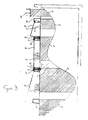
- each unit of electrical equipment has a front side 10 comprising a face plate with an array of connectors 12 disposed thereon.
- the width of the face plate is an industry standard width, being an integral multiple of a basic unit.
- the major part of the electrical equipment is disposed in a housing 14, which may itself comprise an assembly of printed circuit boards, extending behind the face plate.
- Mounted along the top edge of the face plate is a section 16 of aluminium extrusion forming an upstanding rib.
- This rib serves a variety of purposes, including that of a handle for removal and insertion of each unit 4 into and out of the associated rack 2.
- the rib carries on its front face a plurality of indicator devices 20, which may take the form of indicator lights, meters etc, and may be coupled via light pipes and/or optical fibres 22 extending through the hollow interior of the rib to various light sources and sources of meter signals 24 on the front face 10 of the equipment or within housing 14. Alternatively the indicator lights, meters etc. may incorporate their own sources.
- the ribs 16 will be arranged in a co-linear array to provide a continuous rib extending along the top edge of the rack.
- the ends of the continuous rib are closed by end pieces 26.
- the bottom edge of the rib has a relatively wide and deep slot 30 and the top edge of the rib has a narrower and shallower groove 32.
- each rack Associated with each rack is a cover plate 34 of smoked or translucent plastic or glass which is inserted into the slots 30,32 carried by a pair of opposing ribs, by pushing the top edge of the plate 34 firmly into deep slot 30 and then aligning the plate with the lower slot 32 and allowing the plate to drop into slot 32, the dimensions of the plate being such that plate 34 is then located in both slots 30,32.
- cover plate 34 provides a space 36 therebehind for accommodating the various connectors 38 and wiring 40 for coupling selected connectors within the arrays 12.
- a pair of opposing side members 54,56 disposed along the vertical edges of the front face of the racks is a pair of opposing side members 54,56, the side members being hinged as at 58 to front side wall sections 60 of the racking system.
- the side wall sections 60 have a generally U-shape, and are welded to main side wall sections 62 which are angled as shown to provide vertical ducts 64.
- Each side member 54,56 extends along a plurality of adjacent racks and has in cross section an angled form.
- the hinged members 54,56 are movable between a closed position C and an open position O. In the closed position the free edge of the side members overlaps the cover pieces 34, and locks 66 are provided so that the side pieces can be locked in the closed position in order to secure the whole of the front side of the racking system against unauthorised entry.
- the side members provide therebehind, vertically extending ducts 68 for routing cable 70 between the various racks.
- two vertical ducts 64,68 for cable management to permit cables to be led between racks.
- Ducts 64 are intended for semi-permanent cables, and a power bus bar 72 is provided for coupling to the cables. Apertures 74 are provided to permit communication between ducts 64 and 68 to permit the passage of wiring from the racks. Ducts 68 are intended for cables which may be required to be changed frequently.
- the front cover pieces 34 may be released from the ribs to enable access to the units of electrical equipment 4 and to enable their removal or insertion.
- racking system for electrical equipment which enables access, interconnections and maintenance to be carried out from the front of the racking system without requiring personnel also to have access to the rear of the system, thus permitting use of the system in confined spaces.
- the racking system is attractive in appearance and has various features indicated above which permit a neat and inexpensive solution to the problems associated with using racking systems in confined spaces.
- racks may be stacked side by side instead or in addition to being stacked vertically above one another, and the side pieces may extend along the top and bottom edges of the racks rather than as shown vertically extending along the side edges of the racks.
- the number of electrical units within each rack will depend on the circumstances and may be a single unit for example a power supply or may comprise a number of separate units, each unit having one or more circuit cards.
- a feature of the system is to bring all the cable management towards the front of the cabinet, eliminating the need for access to the rear or side of the cabinet. All interconnections between the racking elements and external sources can, potentially, be facilitated towards the front of the cabinet. To disguise the abundance of connectors and cables a number of small panels, that complement the sizes and displacement of the racking elements, are fitted.
- the main cable trunking runs in the vertical plane along either side of the cabinet and is concealed by hinged covers that run the length of the cabinet. Unlike a hinged door or panel which usually conceals the whole face of the cabinet, these hinged covers conceal the localised area to either side, therefore the access is greatly improved and space requirements minimised. These covers can also be locked to secure the panels which, in turn, prevents unauthorised access to the racking elements.
- the cabinet has an overall neat and tidy appearance which is achieved by the introduction of the modular upstanding ribs that are connected to the electrical equipment carried by the racking system. These upstanding ribs have several functions.
- the ribs act as handles for removing the units of electrical equipment from the racking system. Furthermore, the ribs provide locating forms into which the panels can be retained, the panels enabling the system to be made tamper and vermin proof. A cavity is defined by the ribs between the front faces of the racking elements and the panels, which enables all cabling and connections to be concealed. Finally, the ribs provide a suitable surface for carrying status indicators such that the status indicators can be viewed proud of the panels.
- the installed racking elements and their associated upstanding ribs create horizontal strips across the cabinet which appear at a variety of heights depending on the configuration in respect of the particular application.
- the panels are in place only the front face of the upstanding ribs which also accommodates any necessary status indicators, are visible. Therefore the completed cabinet has a smart overall appearance with only the covers, panels and the front facia of the upstanding ribs carrying the status indicators, exposed.
- This format allows the service engineer to see if the unit is functioning correctly, without opening a door or touching it, by interpreting the information from the status indicators. If there is a fault the engineer simply opens the appropriate covers and removes the panels either side of the suspect racking elements. The individual racking units and their interconnections. are exposed which can then be removed or replaced to repair the system.
- the electrical cables are parallel to the surfaces of the units of the electrical equipment so as to allow the insertion or removal of a particular unit without disturbing the cables for adjacent units.
- Such an arrangement necessitates the use of electrical cabling which is capable of sharp 90° bends. This may be achieved by the use of expanded foam cable, as is manufactured, for example by W. L. Gore (UK) Limited. Alternatively, ribbon or film cables may be used.
- racking systems in accordance with the invention may house a wide range of electrical equipment, this usually, but not always, taking the form of electronic assemblies.
Landscapes
- Engineering & Computer Science (AREA)
- Microelectronics & Electronic Packaging (AREA)
- Structure Of Telephone Exchanges (AREA)
- Mounting Of Printed Circuit Boards And The Like (AREA)
- Casings For Electric Apparatus (AREA)
Applications Claiming Priority (2)
| Application Number | Priority Date | Filing Date | Title |
|---|---|---|---|
| GB8920852 | 1989-09-14 | ||
| GB898920852A GB8920852D0 (en) | 1989-09-14 | 1989-09-14 | Racking system |
Publications (2)
| Publication Number | Publication Date |
|---|---|
| EP0417961A2 true EP0417961A2 (de) | 1991-03-20 |
| EP0417961A3 EP0417961A3 (en) | 1991-12-27 |
Family
ID=10663087
Family Applications (1)
| Application Number | Title | Priority Date | Filing Date |
|---|---|---|---|
| EP19900309683 Withdrawn EP0417961A3 (en) | 1989-09-14 | 1990-09-04 | Racking system |
Country Status (4)
| Country | Link |
|---|---|
| EP (1) | EP0417961A3 (de) |
| JP (1) | JPH03175699A (de) |
| AU (1) | AU6243490A (de) |
| GB (2) | GB8920852D0 (de) |
Cited By (1)
| Publication number | Priority date | Publication date | Assignee | Title |
|---|---|---|---|---|
| GB2327181A (en) * | 1997-07-14 | 1999-01-20 | Dsc Telecom Lp | Wiring arrangement in an equipment rack |
Families Citing this family (2)
| Publication number | Priority date | Publication date | Assignee | Title |
|---|---|---|---|---|
| JP6349145B2 (ja) * | 2014-05-12 | 2018-06-27 | 河村電器産業株式会社 | ラック列給電システム |
| KR200484505Y1 (ko) * | 2015-03-25 | 2017-09-13 | 대신정밀 주식회사 | 알루미늄 랙 캐비넷 조립체 |
Family Cites Families (3)
| Publication number | Priority date | Publication date | Assignee | Title |
|---|---|---|---|---|
| GB801919A (en) * | 1957-05-25 | 1958-09-24 | Automatic Telephone & Elect | Improvements in or relating to electrical equipment mounting racks |
| GB1340580A (en) * | 1971-03-11 | 1973-12-12 | Telettra Lab Telefon | Racks for electrical telecommunication equipment |
| EP0057580B1 (de) * | 1981-01-30 | 1987-07-22 | Hitachi, Ltd. | Gestellanordnung für elektronische Anlagen |
-
1989
- 1989-09-14 GB GB898920852A patent/GB8920852D0/en active Pending
-
1990
- 1990-09-04 GB GB9019305A patent/GB2235865A/en not_active Withdrawn
- 1990-09-04 EP EP19900309683 patent/EP0417961A3/en not_active Withdrawn
- 1990-09-12 JP JP24017490A patent/JPH03175699A/ja active Pending
- 1990-09-12 AU AU62434/90A patent/AU6243490A/en not_active Abandoned
Cited By (3)
| Publication number | Priority date | Publication date | Assignee | Title |
|---|---|---|---|---|
| GB2327181A (en) * | 1997-07-14 | 1999-01-20 | Dsc Telecom Lp | Wiring arrangement in an equipment rack |
| US5939673A (en) * | 1997-07-14 | 1999-08-17 | Airspan Communications Corporation | Housing for an equipment rack |
| GB2327181B (en) * | 1997-07-14 | 2001-05-02 | Dsc Telecom Lp | A housing for an equipment rack |
Also Published As
| Publication number | Publication date |
|---|---|
| EP0417961A3 (en) | 1991-12-27 |
| JPH03175699A (ja) | 1991-07-30 |
| GB8920852D0 (en) | 1989-11-01 |
| GB2235865A (en) | 1991-03-20 |
| GB9019305D0 (en) | 1990-10-17 |
| AU6243490A (en) | 1991-03-21 |
Similar Documents
| Publication | Publication Date | Title |
|---|---|---|
| US6912349B2 (en) | Wall mount chassis | |
| US5227957A (en) | Modular computer system with passive backplane | |
| US6101773A (en) | Wire management system | |
| US6245998B1 (en) | Cable management assembly for equipment racks | |
| US6515227B1 (en) | Fiber optic cable management enclosure with integral bend radius control | |
| EP0333618B1 (de) | Kabelanordnungssystem und Baugruppe | |
| US5095403A (en) | Low voltage switchboard | |
| US20020079791A1 (en) | Chassis with repositionable plates | |
| US5773763A (en) | Mounting device for communication RJ elements (patch panel) which has a rear cable guide strip and a front cable guide ring | |
| AU2002235227A1 (en) | Chassis with repositionable plates | |
| KR100265518B1 (ko) | 적응형 카드 장착 시스템 | |
| US5508886A (en) | Electrical system consisting of individual subassemblies | |
| JP2000506316A (ja) | 電気機器のモジュール | |
| EP1344438B1 (de) | Baugruppenträger für von der vorderseite und rückseite eingeschobenen einschübe | |
| US7037143B2 (en) | Front access lan and timing (SATT) | |
| AU671776B2 (en) | Modular wall-mounted equipment enclosure | |
| US5175673A (en) | Distributor for use in communication systems | |
| KR960010740B1 (ko) | 전기 조립체 수납용 하우징 | |
| EP0417961A2 (de) | Baugruppenträger | |
| US20070232134A1 (en) | Protective cover for rack mounted networking equipment | |
| CN104160715B (zh) | 用于形成模块化配电板的系统以及用于组装所述模块化配电板的方法 | |
| EP1835587A1 (de) | Kasten für Schaltschrankgehäuse | |
| US7039291B1 (en) | Card rack | |
| US5315487A (en) | Method and device for coding printed circuit boards | |
| EP0136853B1 (de) | Hülle für einen Vielfachstecker für elektrische Verbindungen mit gedruckten Schaltungen |
Legal Events
| Date | Code | Title | Description |
|---|---|---|---|
| PUAI | Public reference made under article 153(3) epc to a published international application that has entered the european phase |
Free format text: ORIGINAL CODE: 0009012 |
|
| AK | Designated contracting states |
Kind code of ref document: A2 Designated state(s): DE FR IT |
|
| PUAL | Search report despatched |
Free format text: ORIGINAL CODE: 0009013 |
|
| AK | Designated contracting states |
Kind code of ref document: A3 Designated state(s): DE FR IT |
|
| STAA | Information on the status of an ep patent application or granted ep patent |
Free format text: STATUS: THE APPLICATION IS DEEMED TO BE WITHDRAWN |
|
| 18D | Application deemed to be withdrawn |
Effective date: 19920630 |