EP0418008A1 - Collier pour conduite - Google Patents
Collier pour conduite Download PDFInfo
- Publication number
- EP0418008A1 EP0418008A1 EP90309865A EP90309865A EP0418008A1 EP 0418008 A1 EP0418008 A1 EP 0418008A1 EP 90309865 A EP90309865 A EP 90309865A EP 90309865 A EP90309865 A EP 90309865A EP 0418008 A1 EP0418008 A1 EP 0418008A1
- Authority
- EP
- European Patent Office
- Prior art keywords
- pipe
- mating
- splines
- channel
- clamp
- Prior art date
- Legal status (The legal status is an assumption and is not a legal conclusion. Google has not performed a legal analysis and makes no representation as to the accuracy of the status listed.)
- Withdrawn
Links
- 238000007789 sealing Methods 0.000 claims abstract description 29
- 230000013011 mating Effects 0.000 claims description 18
- 210000005069 ears Anatomy 0.000 claims description 6
- 238000012856 packing Methods 0.000 claims description 6
- 230000008901 benefit Effects 0.000 description 9
- 239000012530 fluid Substances 0.000 description 9
- 230000008878 coupling Effects 0.000 description 8
- 238000010168 coupling process Methods 0.000 description 8
- 238000005859 coupling reaction Methods 0.000 description 8
- 230000008439 repair process Effects 0.000 description 7
- 230000006835 compression Effects 0.000 description 6
- 238000007906 compression Methods 0.000 description 6
- 239000002184 metal Substances 0.000 description 6
- 230000036316 preload Effects 0.000 description 5
- 238000000926 separation method Methods 0.000 description 5
- 238000005452 bending Methods 0.000 description 4
- 238000001125 extrusion Methods 0.000 description 4
- 238000009434 installation Methods 0.000 description 3
- 239000000463 material Substances 0.000 description 3
- 230000000717 retained effect Effects 0.000 description 3
- 229910000831 Steel Inorganic materials 0.000 description 2
- 230000009471 action Effects 0.000 description 2
- 238000005266 casting Methods 0.000 description 2
- 229920001971 elastomer Polymers 0.000 description 2
- 238000005242 forging Methods 0.000 description 2
- 238000000034 method Methods 0.000 description 2
- 239000010959 steel Substances 0.000 description 2
- XLYOFNOQVPJJNP-UHFFFAOYSA-N water Substances O XLYOFNOQVPJJNP-UHFFFAOYSA-N 0.000 description 2
- 238000003466 welding Methods 0.000 description 2
- 230000003466 anti-cipated effect Effects 0.000 description 1
- 230000004888 barrier function Effects 0.000 description 1
- 230000007797 corrosion Effects 0.000 description 1
- 238000005260 corrosion Methods 0.000 description 1
- 230000007547 defect Effects 0.000 description 1
- 230000007812 deficiency Effects 0.000 description 1
- 238000013461 design Methods 0.000 description 1
- 238000009826 distribution Methods 0.000 description 1
- 238000005553 drilling Methods 0.000 description 1
- 239000000806 elastomer Substances 0.000 description 1
- 238000003780 insertion Methods 0.000 description 1
- 230000037431 insertion Effects 0.000 description 1
- 230000014759 maintenance of location Effects 0.000 description 1
- 238000004519 manufacturing process Methods 0.000 description 1
- 238000012986 modification Methods 0.000 description 1
- 230000004048 modification Effects 0.000 description 1
- 238000005457 optimization Methods 0.000 description 1
- 230000009467 reduction Effects 0.000 description 1
- 238000006467 substitution reaction Methods 0.000 description 1
Images

Classifications
-
- F—MECHANICAL ENGINEERING; LIGHTING; HEATING; WEAPONS; BLASTING
- F16—ENGINEERING ELEMENTS AND UNITS; GENERAL MEASURES FOR PRODUCING AND MAINTAINING EFFECTIVE FUNCTIONING OF MACHINES OR INSTALLATIONS; THERMAL INSULATION IN GENERAL
- F16L—PIPES; JOINTS OR FITTINGS FOR PIPES; SUPPORTS FOR PIPES, CABLES OR PROTECTIVE TUBING; MEANS FOR THERMAL INSULATION IN GENERAL
- F16L55/00—Devices or appurtenances for use in, or in connection with, pipes or pipe systems
- F16L55/16—Devices for covering leaks in pipes or hoses, e.g. hose-menders
- F16L55/168—Devices for covering leaks in pipes or hoses, e.g. hose-menders from outside the pipe
- F16L55/17—Devices for covering leaks in pipes or hoses, e.g. hose-menders from outside the pipe by means of rings, bands or sleeves pressed against the outside surface of the pipe or hose
- F16L55/1705—Devices for covering leaks in pipes or hoses, e.g. hose-menders from outside the pipe by means of rings, bands or sleeves pressed against the outside surface of the pipe or hose with a substantially radial tightening member
Definitions
- the field of this invention relates to pipe jackets or clamps disposed around a tubular member having fluid flow therethrough and, more particularly, to clamps or jackets for repairing a leaking or damaged pipeline.
- More and more pipelines are being used to carry oil or gas from offshore oil and gas well drilling and production locations to facilities located either offshore or on a nearby land mass.
- these underwater pipelines are comprised of sections of pipe which are interconnected by welding and rest underwater on the river bottom or ocean floor, often in limited access areas or environments. From time to time, such pipelines become damaged or leak due to corrosion, weld failure, or damage due to ship anchors.
- a diver, submarine robot, or combination thereof may be employed to direct a repair coupling or clamp to the point of damage or leakage and repair the pipe by properly affixing the coupling or clamp around the damaged or leaking pipe.
- the repair couplings and clamps must be maneuverable under water with a minimum of connections and mechanical parts which must be implemented during installation. In some instances, large pipeline clamps may weigh over one ton making them difficult to maneuver under water and align for connection around the damaged or leaking pipe.
- pipeline repair clamps or jackets surround the damaged or leaking portion of the pipeline so as to seal off the leakage.
- clamps for underwater pipelines are comprised of two halves with means for securely connecting the halves around the damaged portion of the pipeline.
- the clamp includes a cylindrical bore which is sized to fit around the pipeline and is of sufficient length to traverse any crack, porosity, or other pipeline defect which is causing the leak.
- the basic closure within the body of the clamp is cylindrical in nature which is an efficient form for pressure retention.
- the jacket halves are commonly connected by bolts and nuts which pass through flanges disposed on the clamp halves. Flange section material is added to the sides of the clamp for bolting requirements.
- a block forging or casting is used depending upon the surface requirements and pressure rating.
- Other connections including a hinge and flange system whereby one edge of each half is hingedly connected, and the other side is flanged for bolt or nut and bolt connection.
- U. S. Patent 1,463,749 discloses a device for preventing leaks comprising a pair of semi-cylindrical plates hinged at one end by knuckles and connected together at the other end by a sliding clamp, which pulls the two plates together, due to its trapezoidal shape.
- U. S. Patent 1,510,838 discloses a pipe coupling having a pair of casing members with flanges spaced 180° apart. The flanges of each casing member meet with the corresponding flange on the other casing so that the sleeves can slide over the casing member. The sleeves secure the casing members together due to the tapered grooves therein, which cooperate with the flanges, that are also tapered.
- U. S. Patent 4,535,822 discloses a conventional pipe jacket for repairing a leak in a pipe.
- the pipe jacket comprises a pair of sleeve segments having radially extending flanges provided with bores for receiving fasteners so as to connect the two sleeves together.
- the internal pressure caused by the leaking pipe creates a separating force internally of the clamp tending to force the clamp halves open.
- This separating force may be calculated as the pressure force within the clamp multiplied times the seal area.
- the clamping force of the clamp on the seals must equal or exceed the separating force. Otherwise, the clamp will leak.
- the standard ANSI flat faced flange uses preloaded bolts and nuts to maintain a uniform closure seal force adequate to resist the pipeline fluid pressure.
- the bolts are uniformly preloaded or torqued to maintain a consistent surface engagement pressure and adequate fastener preload.
- a uniform load or torque must be applied to every bolt or stud. Usually several passes are required at tightening the bolts or studs to obtain an adequate fastener and seal surface preload.
- the present invention overcomes the deficiencies of the prior art.
- the present invention is directed to a pipe jacket seal and clamp, which is placed around the leak in a pipe so as to seal the damaged pipe.
- the pipe clamp comprises a pair of semi-annular housing members having sealing elements around their periphery for sealingly encasing the damaged pipe.
- Each semi- annular housing has two longitudinal splines spaced 180° apart. The splines have their side walls tapered, so that when a channel lock bar, which has a channel with correspondingly tapered inner side ramps, is attached to the splines, the semi-annular housing members are pulled together.
- the channel lock bars are secured to the splines by threaded studs extending from each spline and through its respective channel lock bar so that a nut may be screwed down to secure the pipe clamp about the damaged pipe.
- bolts can be used extending through the channel locking bars into threaded holes in the splines.
- the present invention has several advantages over the prior art.
- the deployment of the inventive clamp requires less labor and time than prior art clamps.
- the channel lock bar achieves a uniform closing force for clamp closure.
- the bolts are reduced in size and number as compared to prior art clamps.
- the weight of the inventive clamp is substantially reduced over that of prior art clamps.
- the structure of the clamp body of the present invention using the lock channel bar is more efficient than the prior art bolted flange closure.
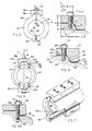
- the pipe jacket or channel lock clamp 10 of the present invention includes a generally cylindrical or tubular body 12 made of two semi-cylindrical or semi-annular housing members 14, 16. Housing members 14, 16 form a cylindrical central bore 18 having a diameter sized for receiving a damaged section of a pipeline.
- the body 12 of channel lock clamp 10 may be made from a steel block, tubular steel, by extrusion, or by casting or forging. It is preferable that the material of the clamp 10 be substantially the same as the material of the pipe to be repaired.
- the clamp 10 of the present invention may be made by extrusion since no clearance is required around the nuts for the bolts or studs which would otherwise prevent a wrench from engaging the nut in conventional clamps. The inscribed circle for the nut clearance of prior art clamps is too large to permit extrusion.
- the weight of the clamp affects the ease of installation and also cost.
- the body 12 of clamp 10 is constructed as light as possible and yet heavy enough so as not to distort under load.
- the body of a 36" prior art clamp weighs approximately 12,000 pounds while that of the present invention weighs only approximately 8,000 pounds.
- the present invention reduces the weight of prior art clamps by 20 to 25%.
- Prior art clamps must be heavier to get the same metal-to-metal contact between clamp halves as the present invention.
- Each semi-annular housing member 14, 16 includes a generally outer arcuate wall 20 and an inner arcuate wall 22 forming central bore 18.
- Outer and inner walls 20, 22 terminate along elongated lateral faces 24, 26 and at end faces 28, 30.
- lateral faces 24, 26 mate along a plane "P" which intersects with the flow axis "F" of central bore 18.
- a counterbore 32 is formed within central bore 18 adjacent each of the end faces 28, 30 by a reduced diameter portion 34 which projects radially inwardly into central bore 18.
- An annular seal 36 having a rectangular cross section, is disposed within counterbore 32 and has a height which is less than the depth of counterbore 32 thereby providing an annular entry space 38 adjacent each end face 28, 30 for receiving an annular packing flange 40.
- Annular packing flange 40 is mounted on each end face 28, 30 by studs or bolts 42 and nuts 44.
- Flange 40 includes apertures 46 for receiving bolts 42.
- Flange 40 includes an annular packing ring 48 having an outer diameter slightly smaller than the inner diameter of annular entry space 38 of counterbore 32 whereby upon the tightening of bolts and nuts 42, 44, packing ring 48 is received with space 38 and engages and compresses annular seal ring 36 to provide an end seal for each end face 28, 30 of clamp 10 which sealingly engages the exterior of the leaking pipe.
- elongated lateral face 26 of housing member 16 includes an elongated recess or groove 50 adjacent inner face 22 for mounting an elongated rectangular sealing element 52 therein.
- the recess or groove 50 has sufficient length to overlap counterbore 32 at each end face 28, 30 such that sealing element 52 sealingly engages annular seals 36.
- the rectangular cross section of sealing element 52 is larger than the cross section of seal groove 50 thereby creating an elongated lateral projecting portion or standoff 56.
- the standoff 56 may extend between .010 and .015 inches from lateral face 26.
- the standoff 56 engages sealing face 24 of housing member 14 preventing the mating engagement of faces 24, 26 and creating a gap G.
- the gap G is sized so as not to be so large as to prevent the channel 86 of lock bar 90 from receiving splines 60 as hereinafter described.
- elongated sealing element 52 mounted in groove 50 of lateral face 26, sealingly engages the opposite lateral face 24 of housing member 14.
- End seals 36 are then compressed to sealingly engage around the damaged pipe and also engage the terminal ends of elongated lateral sealing element 52 at 58.
- lateral sealing element 52 and annular seals 36 mounted around the periphery of housing members 14, 16, completely seal around the leaking portion of the pipe.
- seals 36, 52 it is important that the preloading and compression of seals 36, 52 be great enough to maintain a sealing load which will be maintained upon the application of the separating force to clamp 10.
- the rubber load on seals 36, 52 is designed to be twice the anticipated internal separating force within the clamp 10.
- housing members 14, 16 each further include a pair of elongated longitudinal ears or splines 60 contiguous with and forming a part of elongated faces 24, 26.
- Each spline 60 includes a tapered side ramp 62 extending the length of spline 60 from a flat top surface 64 to a parallel flat side surface 66.
- splines 60 include a plurality of threaded holes 68 adapted for receiving studs 70 as hereinafter described.
- the side ramp 62 forms a wedge angle "A" with the plane P of lateral faces 24, 26.
- the clamp 10 further includes a channel lock bar 90 having a generally rectangular cross section with a longitudinal channel 86 having a channel bottom 84, side ramps 82, and end walls 80.
- Side ramps 62 and 82 form a ramp or wedge having angle A with plane P such that side ramps 82 will slidingly interact with side ramps 62 of splines 60.
- Channel lock bar 90 further includes apertures 88 for receiving studs 70 aligned with bores 68 of splines 60 for attaching bar 90 to splines 60. It can be appreciated that other means may be used as closing components such as hydraulic cylinders, cam actuation and ratchets.
- Studs 70 are preferably located in threaded holes 68 between lateral spline faces 24, 26 and side ramps 62, 82.
- Figure 4A illustrates an alternative location of studs 70 through side ramps 62, 82.
- Bolts or studs 70 located inside ramps 62 provide an inside bending moment so as to increase the contact between housing members 14, 16 and apply a positive sealing force to elongated sealing element 52.
- wedge angle A determines the amount of bolt load "F B " required for side ramps 62, 82 to apply a sufficient load or clamping force "F s " on elongated sealing elements 52. Studs 70 apply a downward force F B on side ramps 62, 82 determined by wedge angle A such that the ramps 62, 82, together with the studs 70, supply the required clamping force F s to close the clamp and apply sealing preload. This clamping force is required to maintain the load on seals 52 for maintaining sealing engagement as well as to fasten the clamp together. As indicated previously, the clamping force often is designed to be approximately twice the separation force.
- the wedge angle A of the present invention also provides a uniform compression force along the length of splines 60 to uniformly compress seals 52.
- the present invention utilizes the mechanical advantage of the wedge angle rather than merely relying on the closing force of the prior art studs or bolts.
- the wedge angle A provides 3 to 5 times the normal mechanical advantage of prior art bolts.
- a 10° wedge angle A provides 5 times (the sine of 10°) the mechanical advantage.
- a 20° wedge angle A provides 2.9 times (the sine of 20°) the mechanical advantage.
- the cosine of 20° permits the use of a bolt 1/5 the size of conventional bolts.
- Wedge angle A must be an angle with a size between a minimum angle causing a self-locking taper and a maximum angle allowing a reasonable gap G for the opening of the clamp and the mounting of channel lock bar 90.
- the gap G between housing members 14, 16 must be small enough to accommodate the insertion of splines 60 into the channel 86 of channel lock bar 90.
- a larger wedge angle A permits a larger gap G between housing members 14, 16 for the assembly of channel lock bar 90, it is preferred to have the smallest wedge angle possible. If the wedge angle A becomes too small, however, the friction area causes the taper between ramps 62, 82 to become self-locking and locks the clamp up. Thus, a locking taper must be avoided.
- the wedge angle A dictates the size of studs 70 and the standoff 56 of sealing element 52. One is exchanged for the other. A smaller wedge angle requires less bolt force F B .
- the studs 70 must be a minimum size so that they will not bend. Larger clamps will use larger studs. The wider the gap G between housing members 14, 16 upon assembly, the larger studs 70 that are required.
- the separating force "F" and the yield stress “Y” of the metal for the clamp body 12 determine the dimensions for splines 60, channel lock bar 90 and studs 70.
- the wedge angle A for side ramps 62 and 82, together with studs 70, must provide a clamping force which will withstand the separating force caused by the retained fluid pressure.
- the load of the separating force must be retained through the length "L” of the direct contact between side ramps 62 and 82.
- the mating engagement of side ramps 62 and 82 allows a uniform load distribution throughout the length L of splines 60.
- the studs 70, used to retain the channel lock bar 90 in its retaining position, are required to hold one component of the separation force F.
- the wedge angle A between side ramps 62, 82 reduces the size and number of studs 70 by withstanding a component of the separation force F.
- the area of side ramp 62 determines the height "H" of side ramp 62.
- the height H is held to a minimum to reduce cross-section binding in the channel lock bar 90 and splines 60.
- the side ramp 62 is loaded to near yield permitting height H to be as small as possible.
- a formula for determining the side ramp height H F/(L ⁇ Y).
- the width "W" of spline 60 must be sufficient to resist the shear caused by the separating force F. Therefore the width W is sized to keep the direct shear below the shear yield point.
- the shear yield point equals 57% of the tensile yield.
- the width W H/.57.
- the wedge angle A is selected to keep the closing component force and studs 70 small and yet allow a sufficient seal gap G to permit the channel lock bar 90 to receive the mating splines 60.
- the size of the seal gap G H ⁇ Tan A.
- the separating force F equals F s Tan A.
- the flat surface 64 Y -H Tan A.
- the width of upper surface 64 is labelled "B” and the width of side surface 66 is labelled "C”.
- the thickness T of channel lock bar 90 must be sufficient to bring the inner surface 86 to the yield point at design load.
- the moment arm MA equals [(H + T)/2] + F.
- the moment per inch for lock channel bar 90 (MA ⁇ F s + Y F s Tan A - HFB)/L.
- a 36" clamp will have a wedge angle of approximately 20° and a bolt size of 1-5/8".
- the channel lock clamp 10 of the present invention incorporates a number of unique features that eliminate the requirement for large bolts and nuts, insures uniform clamping action, reduces overall clamp size and weight, facilitates assembly, and shortens installation time. Overall, the components of the clamp 10 are lighter and easier to handle enabling the assembly procedure to require less effort.
- the unique channel bar arrangement provides a uniform clamping load along the complete length of the body. Seal surfaces are uniformly preloaded by the force exerted through the cam angles of the channel bars and splines. The channel bars and splines achieve a uniform preload using the mechanical advantage of the wedge angle making up the channel bar and splines. As a result of this mechanical advantage, bolting or other fastener means are reduced in magnitude and size.
- clamp 10 establishes a seal between the pipe outside diameter and the central clamp bore 18.
- a number of methods may be employed to achieve such end seals.
- split seals 94 may be circumferentially deployed in grooves 92 within the central clamp bore 18. Sealing engagements with the pipe outside diameter is achieved by closing the clamp 10 around the pipe causing an initial compression and loading the seal 94 against pipe outside diameter. There is sufficient precompression to form a closed seal barrier that resists annular pressure in the clamp cavity.
- a higher pressure or enhanced reliability requires the packing flange arrangement disclosed in the preferred embodiment.
Landscapes
- Engineering & Computer Science (AREA)
- General Engineering & Computer Science (AREA)
- Mechanical Engineering (AREA)
- Flanged Joints, Insulating Joints, And Other Joints (AREA)
Applications Claiming Priority (2)
| Application Number | Priority Date | Filing Date | Title |
|---|---|---|---|
| US40536389A | 1989-09-11 | 1989-09-11 | |
| US405363 | 1989-09-11 |
Publications (1)
| Publication Number | Publication Date |
|---|---|
| EP0418008A1 true EP0418008A1 (fr) | 1991-03-20 |
Family
ID=23603396
Family Applications (1)
| Application Number | Title | Priority Date | Filing Date |
|---|---|---|---|
| EP90309865A Withdrawn EP0418008A1 (fr) | 1989-09-11 | 1990-09-10 | Collier pour conduite |
Country Status (1)
| Country | Link |
|---|---|
| EP (1) | EP0418008A1 (fr) |
Cited By (3)
| Publication number | Priority date | Publication date | Assignee | Title |
|---|---|---|---|---|
| EP0779465A1 (fr) * | 1995-12-14 | 1997-06-18 | British Gas plc | Collier de réparation pour tuyaux |
| CN102444658A (zh) * | 2011-12-21 | 2012-05-09 | 柳州欧维姆机械股份有限公司 | 哈弗式锁紧螺母 |
| JP2013204806A (ja) * | 2012-03-29 | 2013-10-07 | Cosmo Koki Co Ltd | ケース体接続方法 |
Citations (3)
| Publication number | Priority date | Publication date | Assignee | Title |
|---|---|---|---|---|
| US1463749A (en) * | 1921-06-03 | 1923-07-31 | Pollak Charles | Device for preventing leaks |
| US4535822A (en) * | 1983-01-21 | 1985-08-20 | The Pipe Line Development Company | Fitting installation device |
| US8705678B1 (en) * | 2011-09-27 | 2014-04-22 | Teledyne Lecroy, Inc. | Multiple channel distributed system and method |
-
1990
- 1990-09-10 EP EP90309865A patent/EP0418008A1/fr not_active Withdrawn
Patent Citations (3)
| Publication number | Priority date | Publication date | Assignee | Title |
|---|---|---|---|---|
| US1463749A (en) * | 1921-06-03 | 1923-07-31 | Pollak Charles | Device for preventing leaks |
| US4535822A (en) * | 1983-01-21 | 1985-08-20 | The Pipe Line Development Company | Fitting installation device |
| US8705678B1 (en) * | 2011-09-27 | 2014-04-22 | Teledyne Lecroy, Inc. | Multiple channel distributed system and method |
Cited By (5)
| Publication number | Priority date | Publication date | Assignee | Title |
|---|---|---|---|---|
| EP0779465A1 (fr) * | 1995-12-14 | 1997-06-18 | British Gas plc | Collier de réparation pour tuyaux |
| US5797432A (en) * | 1995-12-14 | 1998-08-25 | British Gas Plc | Pipe repair clamp |
| GB2308171B (en) * | 1995-12-14 | 1999-11-03 | British Gas Plc | Pipe repair clamp |
| CN102444658A (zh) * | 2011-12-21 | 2012-05-09 | 柳州欧维姆机械股份有限公司 | 哈弗式锁紧螺母 |
| JP2013204806A (ja) * | 2012-03-29 | 2013-10-07 | Cosmo Koki Co Ltd | ケース体接続方法 |
Similar Documents
| Publication | Publication Date | Title |
|---|---|---|
| RU2613361C2 (ru) | Устройство и способ для уплотнения трубы и способ изготовления указанного устройства | |
| US5590913A (en) | Pipeline connector for connecting a branch pipe to a carrier pipe | |
| US4139221A (en) | Ball and socket joint | |
| US5161828A (en) | Break-away flowline fitting | |
| US4448448A (en) | Coupling system | |
| US4535822A (en) | Fitting installation device | |
| US4138147A (en) | Coupling device | |
| US4608739A (en) | Connector of and sealing of tubular members | |
| CA1305645C (fr) | Collecteur et dispositif de montage de robinet | |
| NO20161399A1 (en) | Bolt, bolt tensioning assembly and method for tensioning of a bolt | |
| US4719687A (en) | Method for sealing, pressure-testing, and transporting a multi-pipe segment | |
| US5908210A (en) | Automated flange retaining clamp with redundant fasteners | |
| US5433482A (en) | Weldless pipe repair apparatus and method | |
| AU595888B2 (en) | Coupling for coupling tubular members | |
| US4124230A (en) | Rigid pipe connector with locking screws and method of making the same | |
| US3685545A (en) | Pipe repair system | |
| US4005879A (en) | Conduit joint | |
| US5195361A (en) | Test method and apparatus for BOP equipment | |
| EP0418008A1 (fr) | Collier pour conduite | |
| US4080799A (en) | Mechanical pipe end seal/alignment device | |
| US3352575A (en) | Pipe coupling for high-pressure gas and oil underwater pipe lines, and process of insalling same | |
| GB2588784A (en) | Clamping system | |
| EP2435743B1 (fr) | Dispositif de raccord de tuyau | |
| WO2000066924A1 (fr) | Systeme d'etancheite de tuyaux | |
| US20240117914A1 (en) | Connector for subsea pipelines and risers, and repair of a pipeline or riser utilizing the connector |
Legal Events
| Date | Code | Title | Description |
|---|---|---|---|
| PUAI | Public reference made under article 153(3) epc to a published international application that has entered the european phase |
Free format text: ORIGINAL CODE: 0009012 |
|
| AK | Designated contracting states |
Kind code of ref document: A1 Designated state(s): AT BE CH DE DK ES FR GB GR IT LI LU NL SE |
|
| RBV | Designated contracting states (corrected) |
Designated state(s): DE FR GB |
|
| STAA | Information on the status of an ep patent application or granted ep patent |
Free format text: STATUS: THE APPLICATION IS DEEMED TO BE WITHDRAWN |
|
| 18D | Application deemed to be withdrawn |
Effective date: 19910921 |