EP0418046B2 - Moteur diesel à régulateur mécanique - Google Patents
Moteur diesel à régulateur mécanique Download PDFInfo
- Publication number
- EP0418046B2 EP0418046B2 EP90309965A EP90309965A EP0418046B2 EP 0418046 B2 EP0418046 B2 EP 0418046B2 EP 90309965 A EP90309965 A EP 90309965A EP 90309965 A EP90309965 A EP 90309965A EP 0418046 B2 EP0418046 B2 EP 0418046B2
- Authority
- EP
- European Patent Office
- Prior art keywords
- fuel injection
- pump
- engine
- governor
- pump housing
- Prior art date
- Legal status (The legal status is an assumption and is not a legal conclusion. Google has not performed a legal analysis and makes no representation as to the accuracy of the status listed.)
- Expired - Lifetime
Links
- 239000000446 fuel Substances 0.000 claims description 127
- 238000002347 injection Methods 0.000 claims description 100
- 239000007924 injection Substances 0.000 claims description 100
- 230000005540 biological transmission Effects 0.000 claims description 63
- 239000010687 lubricating oil Substances 0.000 claims description 19
- 239000000110 cooling liquid Substances 0.000 claims description 8
- 238000010276 construction Methods 0.000 description 16
- 238000012423 maintenance Methods 0.000 description 9
- 238000004519 manufacturing process Methods 0.000 description 9
- 239000003921 oil Substances 0.000 description 7
- 230000003247 decreasing effect Effects 0.000 description 4
- 238000005452 bending Methods 0.000 description 3
- 238000002485 combustion reaction Methods 0.000 description 3
- 230000002093 peripheral effect Effects 0.000 description 3
- 239000007858 starting material Substances 0.000 description 3
- 238000005192 partition Methods 0.000 description 2
- 238000007789 sealing Methods 0.000 description 2
- 239000007787 solid Substances 0.000 description 2
- 238000012790 confirmation Methods 0.000 description 1
- 238000005516 engineering process Methods 0.000 description 1
- 230000008595 infiltration Effects 0.000 description 1
- 238000001764 infiltration Methods 0.000 description 1
- 238000003780 insertion Methods 0.000 description 1
- 230000037431 insertion Effects 0.000 description 1
- 230000003584 silencer Effects 0.000 description 1
Images


Classifications
-
- F—MECHANICAL ENGINEERING; LIGHTING; HEATING; WEAPONS; BLASTING
- F02—COMBUSTION ENGINES; HOT-GAS OR COMBUSTION-PRODUCT ENGINE PLANTS
- F02B—INTERNAL-COMBUSTION PISTON ENGINES; COMBUSTION ENGINES IN GENERAL
- F02B67/00—Engines characterised by the arrangement of auxiliary apparatus not being otherwise provided for, e.g. the apparatus having different functions; Driving auxiliary apparatus from engines, not otherwise provided for
-
- F—MECHANICAL ENGINEERING; LIGHTING; HEATING; WEAPONS; BLASTING
- F02—COMBUSTION ENGINES; HOT-GAS OR COMBUSTION-PRODUCT ENGINE PLANTS
- F02D—CONTROLLING COMBUSTION ENGINES
- F02D1/00—Controlling fuel-injection pumps, e.g. of high pressure injection type
- F02D1/02—Controlling fuel-injection pumps, e.g. of high pressure injection type not restricted to adjustment of injection timing, e.g. varying amount of fuel delivered
- F02D1/04—Controlling fuel-injection pumps, e.g. of high pressure injection type not restricted to adjustment of injection timing, e.g. varying amount of fuel delivered by mechanical means dependent on engine speed, e.g. using centrifugal governors
-
- F—MECHANICAL ENGINEERING; LIGHTING; HEATING; WEAPONS; BLASTING
- F02—COMBUSTION ENGINES; HOT-GAS OR COMBUSTION-PRODUCT ENGINE PLANTS
- F02M—SUPPLYING COMBUSTION ENGINES IN GENERAL WITH COMBUSTIBLE MIXTURES OR CONSTITUENTS THEREOF
- F02M39/00—Arrangements of fuel-injection apparatus with respect to engines; Pump drives adapted to such arrangements
- F02M39/02—Arrangements of fuel-injection apparatus to facilitate the driving of pumps; Arrangements of fuel-injection pumps; Pump drives
-
- F—MECHANICAL ENGINEERING; LIGHTING; HEATING; WEAPONS; BLASTING
- F02—COMBUSTION ENGINES; HOT-GAS OR COMBUSTION-PRODUCT ENGINE PLANTS
- F02B—INTERNAL-COMBUSTION PISTON ENGINES; COMBUSTION ENGINES IN GENERAL
- F02B3/00—Engines characterised by air compression and subsequent fuel addition
- F02B3/06—Engines characterised by air compression and subsequent fuel addition with compression ignition
Definitions
- the present invention relates to a diesel engine with a mechanical governor, and pertains to a technology for providing an ultra small diesel engine.
- a diesel engine with a mechanical governor for example as shown in Fig. 10 or Fig. 11, has been known the one having a following basic construction.
- the arrow F and the arrow B in Figs. indicate the front and the back of the engine respectively.
- a fuel injection pump 245, 445 and a fuel injection cam shaft 246, 446 are provided in the pump housing 244, 444.
- Atiming transmission case 249, 449 is fixedly secured to the front portions of the cylinder block 203, 403 and the pump housing 244, 444.
- the fuel injection cam shaft 246, 446 is interlockingly connected to a crankshaft through a timing transmission device 250, 450.
- a governor spring 329, 529 and a governor weight 340, 540 are interacted with a rack pin 299, 499 of a control rack of the fuel injection pump 245, 445 through a governor lever 315, 515 of a mechanical governor 247, 447.
- the governor weight 340 and a governor sleeve 341 formed as a centrifugal force transmission member are supported by a weight driving shaft 349 underneath the fuel injection cam shaft 246, a weight driving shaft input gear 350 is interlockingly connected to a fuel injection cam shaft input gear 253, and the fore end portion of the governor lever 315 is introduced into the interior of the timing transmission case 249.
- the governor weight 540 and a governor sleeve 541 provided as a centrifugal force transmission member are supported by the fuel injection cam shaft 446.
- the governor weight 540 and the governor sleeve 541 are disposed behind a fuel injection cam shaft input gear 453, and a governor lever 515 and most of the governor spring 529 are disposed within the timing transmission case 449.
- JP-A-55/51086 discloses a diesel engine with a mechanical governor, including a cylinder block having integral therewith a pump housing for a fuel injection pump unit at one side thereof, a fuel injection unit and a fuel injection camshaft provided within the pump housing, a front portion of the fuel injection camshaft being rotatably supported by a fuel injection camshaft bearing, a front portion of the fuel injection camshaft being rotatably supported by a fuel injection camshaft bearing, a timing transmission case secured to the front portions of the cylinder block and the pump housing, the fuel injection camshaft being connected to a crankshaft through a timing transmission device within the timing transmission case, and both a governor spring and a governor weight of a mechanical governor interconnected to a fuel quantity adjusting means of the fuel injection pump through a governor lever, the governor weight and a transmission member for transmitting forces centrifugally generated by the governor weight being supported by the fuel injection camshaft.
- DE-A-36 36 933 discloses a mechanical governor supported by a fuel injection camshaft.
- the governor includes a governor spring and governor weight interconnected to a fuel quantity adjusting means of a fuel injection pump.
- the governor arrangement is supported on the fuel injection camshaft of DE-A-36 36 933 at a position between the fuel injection camshaft drive wheel and the bearing supporting the fuel injection camshaft.
- a diesel engine according to the invention is characterised in that the governor weight and the transmission member are arranged between the fuel injection camshaft bearing and the fuel injection pump, and are supported by the fuel injection camshaft within the pump housing, and the governor lever and governor spring are disposed within the pump housing in such a manner as not to enter the timing transmission case.
- An engine of this embodiment has been manufactured by way of trial in order to provide an ultra small diesel engine.
- the engine is of the vertical liquid-cooled overhead camshaft type and has the total stroke volume of 300 cc composed of two combustion chambers of 150 cc.
- the output of the diesel engine is set at 9 h.p./ 4500 rpm.
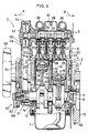
- a cylinder block 3 of an engine body 2 comprises a cylinder portion 4 and an upper crankcase 5 integratedly formed up and down.
- a lower crankcase 6 and an oil pan 7 are fixedly secured in order to the lower portion of the cylinder block 3.
- a cylinder head 8 and a head cover 9 are fixedly secured in order to the upper portion of the cylinder block 3.
- a breather chamber 10 is projected upward from the central portion of the head cover 9.
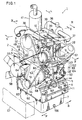
- the engine body 2 is adapted to be mounted to an engine working machine such as an engine generator and the like through four threaded holes 11 ( refer to Fig. 1) formed in both the left and right sides of the lower crankcase 6 respectively.
- a crankshaft 13 is disposed between the upper crankcase 5 and the lower crankcase 6 so as to extend in the fore and back direction and rotatably supported by a plurality of bearings 14.
- a piston 16 is slidably inserted into each of two cylinders 15 of the cylinder portion 4.
- a piston pin 17 of each piston 16 is connected to the crankshaft 13 through a connecting rod 18.
- a combustion chamber 19 is disposed above each piston 16, and a cylinder jacket 20 is disposed around each cylinder 15.
- the cylinder head 8 has intake valves 25, 25 mounted at intake ports 23, 23 and exhaust valves 26, 26 mounted at exhaust ports 24, 24, and further has a fuel injection nozzle 28 and a glow plug 29 mounted in a divided combustion chamber 27 and a head jacket 30 formed around the ports 23, 24.
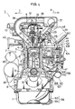
- Two fuel injection nozzles 28, 28 are mounted to the right wall portion of the cylinder head 8 symmetrically with respect to the fore and back directed center line ( refer to Figs. 1 and 3).
- a valve actuating camshaft 33 is supported between the cylinder head 8 and the head cover 9 so as to extend in the fore and back direction.
- a partition plate 34 disposed above the camshaft 33 serves to prevent lubricating oils scattered within the cylinder head 8 and the head cover 9 from entering the breather chamber 10.
- An intake air for the engine is introduced from an air cleaner 36 disposed behind the cylinder head 8 into the intake ports 23, 23 through a surge tank 37 disposed on the right upper side of the head cover 9 so as to extend in the fore and back direction and intake pipes 38, 38 disposed both on the foreside and on the backside of the breather chamber in order.
- the surge tank 37 is so constructed as to function as a resonance intake silencer.
- the breather chamber 10 is intercommunicated with the surge tank 37 through a breather pipe 39.
- An exhaust gas of the engine is discharged outside from the respective exhaust ports 24, 24 through an exhaust manifold 40 ( refer to Fig. 4 ) and an exhaust muffler 41 ( refer to Fig. 4 ) disposed on the left back side of the engine body 2 in order.
- a fuel injection pump unit 43 has a pump housing 44 integratedly formed with the cylinder portion 4 on the right lateral side of the cylinder block 3.
- a fuel injection pump 45, a fuel injection camshaft 46 and a mechanical governor 47 are mounted within the pump housing 44.
- the fuel injection pump 45 is disposed substantially at the central portion of the cylinder block 3 in the fore and back direction.
- two injection pipes 48, 48 which connects each pump element (not illustrated ) within the pump 45 to each fuel injection nozzle 28 are arranged symmetrically in a short piping length.
- the fuel injection camshaft 46 is disposed in the space below the pump 45 so as to extend in the fore and back direction.
- a timing transmission case 49 is fixedly secured to the fore portions of the cylinder block 3 and the pump housing 44.
- a toothed belt transmission type timing transmission device 50 is disposed. That is, a timing output pulley 51, a valve actuating input pulley 52 and a fuel injection camshaft input pulley ( input wheel means ) 53 are fixedly secured to each fore end portion of the crankshaft 13, the valve actuating camshaft 33 and the fuel injection camshaft 46 respectively.
- a toothed belt 54 is wrapped around these pulleies 51, 52, 53.
- a tension pulley 55 is disposed between the output pulley 51 and the valve actuating input pulley 52.
- a radiator 57 ( indicated by an alternate long and two short dashes line in Fig. 1) is disposed in the space in front of the engine body 2 having the above-mentioned construction.
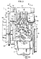
- a radiator fan 58 is connected to the fore end portion of a pump shaft 60 ( refer to Fig. 2 ) of an engine cooling liquid circulation pump 59 fixedly secured on the left upper portion of the cylinder block 3.
- a belt transmission device 62 is arranged in the front space outside the timing transmission case 49. That is, an engine attachment driving output pulley 63 is fixedly secured to the fore end portion of the crankshaft 13 in front of the timing output pulley 51.
- a fan input pulley 64 is fixedly secured to the back portion of the radiator fan 58, and a tension pulley 67 as a belt tension means 66 is fixedly secured to a dynamo 65 disposed at the right upper position of the timing transmission case 49.
- a V-transmission belt 68 is wrapped around these pulleies 63, 64, 67.
- the belt tension means 66 is disposed in the fore space above the fuel injection pump and on the right lateral side of the cylinder head 8 so as to be constructed as shown in Fig. 2.
- a dynamo base plate is pivotally supported at its lower portion by the engine body 2 through a lower bolt 71.
- a bracket 72 is fixedly secured to the upper portion of the engine body 2.
- the base plate 70 is fixedly secure at its upper portion to the bracket 72 so as to be pivotally adjustable by means of an upper bolt 74 inserted into a guide groove 73 of the bracket 72.
- the engine cooling liquid When the circulation pump 59 is driven, the engine cooling liquid is circulated as follows. Mainly as shown in Fig. 2, the engine cooling liquid passes through an inlet nozzle 76 of the circulation pump 59, the cylinder jacket 20 and the head jacket 30 in order from the lower portion of the radiator 57 and then returns to the upper portion of the radiator 57 from an outlet nozzle 77 provided at the left upper portion of the cylinder head 8.
- the cooling liquid is air-cooled by means of the fan 58 during the downward flowing thereof within the radiator 57.
- a flywheel 79 is fixedly secured to the output portion of the crankshaft 13 at the back end.
- a starter 80 and a starter motor 81 is fixedly secured to the left back portion of the engine body 2, and an output pinion of the starter 80 at the back end is adapted to be engaged with a ring gear 82 of the fly wheel 79.
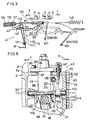
- a pump mounting bore 86 and a pump receiving seat 87 for mounting the fuel injection pump 45 are formed in an upper wall 85 of the pump housing 44.
- the upper surface of the pump receiving seat 87 is so formed as to be about at the same level as a cylinder head receiving surface 3a provided in the upper surface of the cylinder block 3.
- the fuel injection pump 45 is so constructed as to be mounted through its flange and has a trunk portion 88 and a mounting flange portion 89 arranged in order from below.
- the trunk portion 88 is inserted into the pump housing 44 through the pump mounting bore 86 from above, and the mounting flange 89 is brought into contact with the upper surface of the pump receiving seat 87 from above and fixedly secured to the housing upper wall 85 by a plurality of bolts 90.
- the fuel injection camshaft 46 is rotatably supported by the pump housing 44 through a fore and a back bearings 91, 92.
- the aforementioned fuel injection camshaft input pulley 53 is fixedly secured to the fore end portion of the camshaft 46, and a pump shaft 94 of a lubricating oil pump 93 ( refer to Fig. 1) is connected to the back end portion of the camshaft 46.
- the aforementioned timing transmission case 49 is fixedly secured to the fore portion of the pump housing 44 so as to cover the input pulley 53 and the toothed belt 54.
- a pump casing 95 is fixedly secured to the back portion of the pump housing 44 so as to cover an oil pump 93.
- Two fuel injection cams 96, 96 are disposed in the back portion of the camshaft 46, and each pump element (not illustrated ) of the fuel injection pump 45 is driven by means of each cam 96 through each tappet 97.
- a mechanical governor 47 is interlocked to a rack pin 99 provided in a fuel quantity adjusting means of the aforementioned fuel injection pump 45 so that the injection quantity of the pump 45 can be controlled to keep an engine revolution at a set value even though an engine load changes.
- the arrow l in Fig. 6 indicates a fuel quantity decreasing direction and the arrow r therein indicates a fuel quantity increasing direction.
- the mechanical governor 47 will be explained with reference to a schematic view of Fig. 9 in addition to Figs. 6 through 8.
- a governor mounting port 101 is formed in the right wall of the pump housing 44, and this mounting port 101 is covered with a cover plate 102.
- a speed control lever 104 ( refer to Figs. 3 and 4 ) is fixedly secured to an outer end of one pin 103 passed through the back portion of the cover plate 102, and a control swivel member 105 is fixedly secured to the inner end of the pin 103.
- a stopper lever 108 ( refer to Figs. 3 and 4 ) is fixedly secured to an outer end of the other pin 107 passed through the fore portion of the cover plate 102, and a stopper swivel member 109 is fixedly secured to an inner end of the pin 107.
- a governor pivot pin 111 is supported by both the left and the right walls of the pump housing 44 through left and right bearings 112, 113.
- the governor lever 115 supported by the pivot pin 111 comprises a spring lever 116 and a rack lever 117.
- the spring lever 116 is swingably supported at its lower portion by the right portion of the pivot pin 111.
- the rack lever 117 comprises swingable plates 119, 120 supported by the pivot pin 111 at the left and right opposite sides of the fuel injection camshaft 46, a connection plate 121 provided between both these plates 119, 120 and a lever portion 122 projected upward from the right swingable plate 120.
- the upper end of the lever portion 122 and the rack pin 99 of the fuel quantity adjusting means are connected by means of a control link 124.
- the fore end of the control link 124 is connected to the upper end of the lever portion 122 through the pin 125, and the rack pin 99 is-fitted into a slot 126 of the control link 124 so as to be freely movable in the fore and back direction.
- a governor spring 129 mounted between the upper end of the spring lever 116 and the upper end of the control swivel member 105 comprises a low revolution speed spring 130 and a high revolution speed spring 131.
- the fore end of the high revolution speed spring 131 is inserted into a slot 133 of the spring lever 116.
- a spring case 136 of a torque spring 135 ( refer to Fig. 9 ) is fixedly secured to the upper end of the spring lever 116.
- the resilient force of the governor spring 129 serves to swingably urge the rack lever 117 in the fuel quantity increasing direction r through spring lever 116, the torque spring 135 within the spring case 136 and a pushing pin 137.
- a plurality of governor weights 140 are supported by the fore portion of the fuel injection camshaft 46 through a bracket 139, and a governor sleeve 141 as a centrifugal force transmission member is fitted around the fore portion thereof so as to be movable in the fore and back direction.
- the centrifugal force of the governor weight 140 is transmitted to respective rollers 143, 144 of the respective swingable plates 119, 120 through the governor sleeve 141 so as to swingably drive the rack lever 117 in the fuel quantity decreasing direction l.
- the rack pin 99 is adapted to be controlled in the fore and back direction so as to keep the engine revolution at a predetermined valve set by the speed control lever 104.
- the afore mentioned rack pin 99 is resiliently urged in the fuel quantity increasing direction r by means of a start spring 145. Further, a fuel limiting member 147 composed of a bolt is vertically passed through the upper wall 85 of the pump housing 44 so as to be oil-tightly and adjustably advanced and retracted. The fuel limiting member 147 is adapted to be brought into stop contact with the spring lever 116 at a full load position D ( refer to Fig. 9 ).
- the rack pin 99 is adapted to be controlled within a fuel control region between the 0/4 load position A and the 4/4 load position ( the full load position ) D according to a balance between the governor weight centrifugal force W and the resultant force of a resilient force M of the low revolution speed spring 130 and a resilient force N of the high revolution speed spring 131.
- the engine speed is kept at the predetermined high revolution speed though the engine load changes.
- the function of the aforementioned torque spring 135 will be explained in greater detail.
- the spring constant of the torque spring 135 is set at a smaller value than the respective spring constants of both the aforementioned governor springs 130, 131. Therefore, when an overload is applied to the engine, the moving speed of the rack pin 99 in the fuel quantity increasing direction r with respect to a variation of the centrifugal force W of the governor weight 140 is adapted to be slowed during a duration for the rack pin 99 to reach an overload position E after having gone over the 4/4 load position D rather than a duration for the rack pin 99 to reach the 414 load position D. Therefore, when the overload is applied, a transit duration to an engine stall can be kept long by slowly lowering the revolution speed of the engine. As a result, it becomes possible to secure a time margin for avoiding such an engine stall.
- the rack pin 99 is controlled within the above-mentioned fuel control region so that the engine revolution speed can be kept at the predetermined low revolution speed.
- the speed control lever 104 shall be operated to the rightmost position in Fig. 9. Then, the spring lever 116 is stopped by means of the fuel limiting member 147 as well as rack lever 117 is swung in the fuel quantity increasing direction r by means of the resilient force of the start spring 145 so that the rack pin 99 can be moved to a starting position 5.
- a stop lever 108 shall be swung to the left side in Fig. 9. Thereby, the rack pin 99 is moved to a stop position P along the slot 126 of the control link 124.
- the stop lever 108 is not subject to a resistance provided by the resilient forces M, N of the governor springs 130, 131 but it is only subject to a resistance provided by the resilient force of the start spring 145. As a result, the engine stopping operation can be rapidly carried out.
- a lubricating oil filter 151 is disposed in the back portion of the space on the right lateral side of the cylinder head 8 and above the fuel injection pump 45.
- This filter 151 is fixedly secured to a filter mounting seat 152 fixedly mounted onto the back portion of the upper wall 85 of the pump housing 44.
- a lubricating oil supply means 155 is disposed in the fore portion of the pump housing 44.
- a lubricating oil drain means 156 and a lubricating oil level check means 157 are arranged below the pump housing 44.
- An engine cooling-liquid drain means 158 is disposed in the lower portion thereof 44.
- the lubricating oil supply means 155 comprises a supply nozzle 160 and a supply cap 161 disposed in the upper portion of the cylinder block 3.
- the lubricating oil drain means 156 comprises a drain nozzle 163 and a plug 164 disposed in the lower portion of the oil pan 7.
- the lubricating oil level check means 157 comprises a gauge insertion nozzle 166 and a level gauge 167 disposed in the upper portion of the lower crankcase 6.
- the engine cooling-liquid drain means 158 comprises a drain nozzle 169 and a plug 170 disposed in the lower portion of the pump housing 44.
- the drain nozzle 169 is formed in the lower end portion of the drain port 171 ( refer to Figs. 4 and 6 ) bored through the lower portion of the pump housing 44 so as to be communicated with the lower portion of the cylinder jacket 20.
- the fuel injection pump 45 is disposed about at the central portion of the cylinder block 3 in the fore and back direction, an advantage of the following item (4) can be provided. (4) Since the injection pipes 48, 48 of the fuel injection pump 45 can be symmetrically arranged in a short piping distance ( refer to Figs. 1 through 3 ), the fuel injection pressure at the fuel injection nozzle 28 can be increased and the fuel injection delay can be restrained. As a result, the engine performance can be improved.
- the upper surface of the pump mounting seat 87 is formed substantially at the same level as the cylinder head receiving surface 3a of the cylinder block 3 and the fuel injection pump 45 of the flange type is mounted onto the upper wall 85 of the pump housing 44 from above, advantages of the following items (5) and (6) can be provided.
- timing transmission device 50 is constructed as the belt transmission type one, an advantage of the following item (7) can be provided. (7) The dimensional accuracy between the crankshaft 13 and the fuel injection camshaft 46 can be made loose and the manufacturing cost of the engine can be reduced.
- the timing transmission device 250, 450 employed in the first conventional embodiment and the second conventional embodiment is modified from the gear type one to the belt transmission type one, it is necessary to construct as indicated by the alternate long and two short dashes line in Fig. 10 or in Fig.11. That is, in order to decrease a load per unit area of the timing belt, it is necessary to make the fuel injection camshaft pulley 653, 853 larger than the gear 253, 453 in diameter. Further, in order to prevent a lowering of a strength of the timing belt 654, 854 caused by an oil infiltration, it is necessary to provide a sealing between the mechanical governor 247, 447 and the timing transmission device 250, 450.
- a governor case 514 can't help being remained between a pump housing 444 and a timing transmission case 649 so as to dispose a governor lever 515, a governor spring 529 and a governor weight 540 within a governor case 514.
- a fuel limiting member 547 is covered with the timing transmission case 649.
- the thickness dimension of the timing transmission case 249 becomes large and the total length of the engine becomes long. Further, since it is necessary to provide a partition wall 327 within a timing transmission case 249 in order to prevent the lubricating oil from entering the timing transmission case 249 from the governor lever 315, the manufacturing cost of the engine becomes high and it takes much labor for the maintenance thereof.
- the belt tension means 66 of the belt transmission device 62 for driving the engine attachments is disposed in the fore portion of the space on the lateral side of the cylinder head 8 and above the fuel injection pump 45 as well as the lubricating oil filter 151 is disposed in the back portion of the aforementioned space, advantages of the following items (13) through (16) can be provided.
- the construction for driving the dynamo 65 can be simplified. Since the transmission belt 68 is wrapped around the radiator fan 58, the engine cooling-liquid circulation pump 59 and the tension pulley 67, also the construction for driving the engine attachments such as the fan 58 and the like can be simplified. Accordingly, the engine manufacturing cost can be reduced and the engine maintenance becomes easy, too.
Landscapes
- Engineering & Computer Science (AREA)
- Chemical & Material Sciences (AREA)
- Combustion & Propulsion (AREA)
- Mechanical Engineering (AREA)
- General Engineering & Computer Science (AREA)
- High-Pressure Fuel Injection Pump Control (AREA)
- Cylinder Crankcases Of Internal Combustion Engines (AREA)
Claims (10)
- Moteur Diesel, à régulateur mécanique, comprenant un bloc-cylindres (3) avec lequel est venu d'une pièce, sur l'un de ses côtés (3), un carter de pompe (44) pour une unité de pompe d'injection de carburant (43), une pompe d'injection de carburant (45) et un arbre à cames d'injection de carburant (46) disposés à l'intérieur du carter de pompe (44), une partie avant de l'arbre à cames d'injection de carburant (46) étant portée à rotation par un palier (91) d'arbre à cames d'injection de carburant porté par la paroi avant du carter de pompe (44), un boîtier de distribution (49) fixé sur les parties avant du bloc-cylindres (3) et du carter de pompe (44), l'arbre à cames d'injection de carburant (46) étant relié à un vilebrequin (13) par l'intermédiaire d'un dispositif de distribution (50) disposé à l'intérieur du boîtier de distribution (49), et un ressort de régulateur (129) et une masselotte centrifuge de régulateur (140), faisant partie d'un régulateur mécanique (47), reliés l'un à l'autre à des moyens de réglage de quantité de carburant de la pompe d'injection de carburant (45) par l'intermédiaire d'un levier de régulateur (115), la masselotte centrifuge de régulateur (140) et une pièce de transmission (141) servant à transmettre les forces produites de manière centrifuge par la masselotte centrifuge de régulateur (140) étant portées par l'arbre à cames d'injection de carburant (46) et étant disposées entre le boîtier de distribution (49) et la pompe d'injection de carburant (45), caractérisé en ce que la masselotte centrifuge de régulateur (140) et la pièce de transmission (141) sont disposés entre le palier (91) d'arbre à cames d'injection de carburant et la pompe d'injection de carburant (45) et sont portées par l'arbre à cames d'injection de carburant (46) à l'intérieur du carter de pompe (44), et en ce que le levier de régulateur (115) et le ressort de régulateur (129) sont disposés à l'intérieur du carter de pompe (44) de manière à ne pas pénétrer dans le boîtier de distribution (49).
- Moteur Diesel suivant la revendication 1, dans lequel la pompe d'injection de carburant (45) est disposée pratiquement à l'endroit de la partie centrale du bloc-cylindres (3) suivant une orientation longitudinale.
- Moteur Diesel suivant l'une des revendications 1 et 2, dans lequel un perçage de montage de pompe (86) et un siège de réception de pompe (87) sont ménagés dans la paroi supérieure (85) du carter de pompe (44), la surface supérieure du siège récepteur de pompe (87) est réalisée pratiquement au même niveau que la surface réceptrice de culasse (3a) du bloc-cylindre (3), et la pompe d'injection de carburant (45) est agencée de façon à être montée par sa collerette et comporte une partie formant boîtier (88), agencée de façon à être introduite dans le carter de pompe (44) par le perçage de montage de pompe (86), et une partie formant collerette de montage (89) agencée de façon à être amenée, par en haut, en contact avec la surface supérieure du siège récepteur de pompe (87), de façon à être fixée à demeure sur ce dernier.
- Moteur Diesel suivant l'une quelconque des revendications 1 à 3, dans lequel le bloc-cylindres (3) comporte des cylindres (15) en nombre pair.
- Moteur Diesel suivant la revendication 4, dans lequel il est prévu deux cylindres (15).
- Moteur Diesel suivant la revendication 3, dans lequel le dispositif de distribution (50) est réalisé sous la forme d'un dispositif de distribution à courroie de transmission, le levier de régulateur (115) est agencé de façon à être arrêté au moyen d'une pièce de limitation de carburant (147) dans une position de pleine charge (D), et la pièce de limitation de carburant (147) traverse le carter de pompe (44) en dehors du boitier de distribution (49) et est portée par ce carter de pompe (44) de façon qu'on puisse la faire avancer et la rétracter d'une manière réglable.
- Moteur Diesel suivant l'une quelconque des revendications 1 à 6, dans lequel des moyens de contrôle de niveau d'huile de lubrification (157) et des moyens de vidange d'huile de lubrification (156) sont disposées au-dessous du carter de pompe (44).
- Moteur Diesel suivant l'une quelconque des revendications 1 à 7, dans lequel un dispositif de transmission à courroie (62) destiné à entraîner un organe auxiliaire du moteur est disposé en avant du boîtier de distribution (49) et est relié à la partie extrême avant du vilebrequin (13) suivant une liaison de verrouillage mutuel, des moyens de tension de courroie (66) sont disposés dans la partie avant de l'espace situé sur le côté latéral de la culasse (8) et au-dessus de la pompe d'injection de carburant (45), et un filtre d'huile de lubrification (151) est disposé dans la partie arrière de l'espace situé sur le côté latéral de la culasse (8) et au-dessus de la pompe d'injection de carburant (45)
- Moteur Diesel suivant la revendication 8, dans lequel une dynamo (65) est reliée à une poulie de tension (67) des moyens de tension de courroie (66).
- Moteur Diesel suivant l'une des revendications 8 et 9, dans lequel ce moteur est du type à refroidissement par liquide, un ventilateur de radiateur (58) et une pompe de circulation de liquide de refroidissement de moteur (59) sont disposés suivant une direction longitudinale en avant du bloc-cylindres (3), et le dispositif de transmission à courroie (62) servant à entraîner l'élément auxiliaire de moteur comprend une poulie de sortie (63) fixée à demeure sur la partie extrême avant du vilebrequin (13), une poulie d'entrée (64) fixée à demeure sur le ventilateur de radiateur (58) et la pompe de circulation (59), une poulie de tension (67) et une courroie de transmission (68) s'enroulant autour de ces poulies (63, 64, 67).
Applications Claiming Priority (6)
| Application Number | Priority Date | Filing Date | Title |
|---|---|---|---|
| JP237605/89 | 1989-09-12 | ||
| JP23760589A JPH0791998B2 (ja) | 1989-09-12 | 1989-09-12 | ディーゼルエンジンにおける燃料噴射ポンプ・オイルフィルタ・ベルトテンション装置の組付け装置 |
| JP1247201A JP2524839B2 (ja) | 1989-09-21 | 1989-09-21 | 遠心式ガバナ付を多気筒ディ―ゼルエンジン |
| JP247201/89 | 1989-09-21 | ||
| JP247202/89 | 1989-09-21 | ||
| JP24720289A JPH073191B2 (ja) | 1989-09-21 | 1989-09-21 | ベルト調時伝動式デイーゼルエンジンの遠心式ガバナ |
Publications (3)
| Publication Number | Publication Date |
|---|---|
| EP0418046A1 EP0418046A1 (fr) | 1991-03-20 |
| EP0418046B1 EP0418046B1 (fr) | 1993-12-01 |
| EP0418046B2 true EP0418046B2 (fr) | 1997-04-16 |
Family
ID=27332490
Family Applications (1)
| Application Number | Title | Priority Date | Filing Date |
|---|---|---|---|
| EP90309965A Expired - Lifetime EP0418046B2 (fr) | 1989-09-12 | 1990-09-12 | Moteur diesel à régulateur mécanique |
Country Status (5)
| Country | Link |
|---|---|
| US (1) | US5083545A (fr) |
| EP (1) | EP0418046B2 (fr) |
| KR (1) | KR0149856B1 (fr) |
| DE (1) | DE69004905T3 (fr) |
| ES (1) | ES2047272T5 (fr) |
Families Citing this family (16)
| Publication number | Priority date | Publication date | Assignee | Title |
|---|---|---|---|---|
| DE4138290A1 (de) * | 1991-11-21 | 1993-05-27 | Kloeckner Humboldt Deutz Ag | Brennkraftmaschine |
| DE4142354C2 (de) * | 1991-12-20 | 2003-04-17 | Stihl Maschf Andreas | Handgeführtes Arbeitsgerät mit einem Verbrennungsmotor und einer Einspritzpumpe |
| AT407557B (de) * | 1993-12-14 | 2001-04-25 | Steyr Nutzfahrzeuge | Befestigung einer einspritzpumpe am kurbelgehäuse einer brennkraftmaschine |
| FR2726033B1 (fr) * | 1994-10-25 | 1996-11-29 | France Design | Moteur thermique pour vehicule automobile equipe d'un dispositif de climatisation a compresseur |
| JP3521555B2 (ja) * | 1995-06-30 | 2004-04-19 | 日産自動車株式会社 | 直接噴射型火花点火機関の燃料供給装置 |
| US6394059B2 (en) * | 2000-01-26 | 2002-05-28 | International Engine Intellectual Property Company, L.L.C. | Front module housing |
| DE60221610T3 (de) * | 2001-09-11 | 2014-12-24 | Kubota Corp. | Brennkraftmaschine |
| US6708507B1 (en) | 2003-06-17 | 2004-03-23 | Thermo King Corporation | Temperature control apparatus and method of determining malfunction |
| GB0526312D0 (en) | 2005-12-23 | 2006-02-01 | Britax Premium Aircraft Interi | Composite panel |
| KR100871611B1 (ko) * | 2007-12-19 | 2008-12-02 | 현대산업엔진(주) | 출력 향상 수단을 구비한 디젤 엔진 발전기 |
| GB201209108D0 (en) * | 2012-05-24 | 2012-07-04 | Delphi Tech Holding Sarl | Internal combustion engine |
| USD763413S1 (en) * | 2013-02-14 | 2016-08-09 | Yanmar Co., Ltd. | Fuel injection pipe |
| USD762823S1 (en) * | 2013-02-14 | 2016-08-02 | Yanmar Co., Ltd. | Fuel injection pipe |
| WO2016133481A1 (fr) * | 2015-02-20 | 2016-08-25 | Sahin Metal Imalat Sanayi Ve Ticaret Anonim Sirketi | Moteur diesel à cylindre unique |
| JP6559097B2 (ja) | 2016-06-30 | 2019-08-14 | 株式会社クボタ | エンジンのオイル冷却構造 |
| JP7385553B2 (ja) * | 2020-12-31 | 2023-11-22 | 株式会社クボタ | エンジン搭載車両 |
Family Cites Families (12)
| Publication number | Priority date | Publication date | Assignee | Title |
|---|---|---|---|---|
| GB1217511A (en) * | 1967-01-11 | 1970-12-31 | Simms Motor Units Ltd | Improvements in or relating to fuel pumps including speed governor devices |
| US3730147A (en) * | 1971-10-29 | 1973-05-01 | Gen Motors Corp | Engine accessory arrangement |
| US4023547A (en) * | 1975-08-06 | 1977-05-17 | Josef Reisacher | Reciprocating-piston-type internal combustion engine particularly for the operation of passenger automobiles |
| JPS5551086A (en) * | 1978-09-04 | 1980-04-14 | Copyer Co Ltd | Novel pyrazoline compound, its preparation, and electrophotographic photosensitive substance comprising it |
| US4403586A (en) * | 1979-12-11 | 1983-09-13 | Yanmar Diesel Engine Co., Ltd. | Fuel injection pump of internal combustion engine |
| AT379865B (de) * | 1980-02-08 | 1986-03-10 | Simmering Graz Pauker Ag | Wassergekuehlte brennkraftmaschine |
| JPS5773330U (fr) * | 1980-10-23 | 1982-05-06 | ||
| US4607601A (en) * | 1984-02-23 | 1986-08-26 | Compagnie Des Transmissions Mechaniques Sedis | Detachable timing gear cassette unit for an explosion or internal combustion engine |
| JPS6314031A (ja) * | 1986-06-30 | 1988-01-21 | Mitsubishi Electric Corp | 空気調和機の制御装置 |
| IT1206949B (it) * | 1987-05-12 | 1989-05-11 | Omap Spa | Pompa a corpo autonomo con sezioni pompante e motrice distinte per iniezioni ad alta pressione dicarburante in motori endotermici. |
| JPS6477725A (en) * | 1987-09-18 | 1989-03-23 | Diesel Kiki Co | Centrifugal governor for injection type internal combustion engine |
| JPH0224411A (ja) * | 1988-07-12 | 1990-01-26 | Mitsubishi Heavy Ind Ltd | 海上埋立工法 |
-
1990
- 1990-09-05 US US07/577,772 patent/US5083545A/en not_active Expired - Fee Related
- 1990-09-12 DE DE69004905T patent/DE69004905T3/de not_active Expired - Fee Related
- 1990-09-12 KR KR1019900014392A patent/KR0149856B1/ko not_active Expired - Fee Related
- 1990-09-12 EP EP90309965A patent/EP0418046B2/fr not_active Expired - Lifetime
- 1990-09-12 ES ES90309965T patent/ES2047272T5/es not_active Expired - Lifetime
Also Published As
| Publication number | Publication date |
|---|---|
| ES2047272T5 (es) | 1997-05-16 |
| EP0418046A1 (fr) | 1991-03-20 |
| EP0418046B1 (fr) | 1993-12-01 |
| KR910006602A (ko) | 1991-04-29 |
| ES2047272T3 (es) | 1994-02-16 |
| DE69004905T2 (de) | 1994-06-30 |
| US5083545A (en) | 1992-01-28 |
| DE69004905T3 (de) | 1997-06-12 |
| KR0149856B1 (ko) | 1999-03-20 |
| DE69004905D1 (de) | 1994-01-13 |
Similar Documents
| Publication | Publication Date | Title |
|---|---|---|
| EP0418046B2 (fr) | Moteur diesel à régulateur mécanique | |
| EP0809004B1 (fr) | Moteur diesel en v | |
| US7178498B2 (en) | Lubrication system for an engine | |
| CN101149003A (zh) | 多气缸内燃机 | |
| EP0857861A1 (fr) | Moteur à combustion interne | |
| US6990942B2 (en) | Balancer structure for engine | |
| KR100741366B1 (ko) | 밸브 제어가 이루어지는 내연기관 | |
| US7104242B2 (en) | Internal combustion engine including splash-resistant oil storage structure | |
| US7029346B2 (en) | Vertical engine and outboard engine system | |
| US7367293B2 (en) | Four-stroke engine | |
| EP0560402B1 (fr) | Moteur à combustion interne de véhicule avec un système de refroidissement liquide | |
| KR100534153B1 (ko) | V형디젤엔진 | |
| JP3633088B2 (ja) | エンジンの補機取付構造 | |
| JP2000110533A (ja) | 多気筒エンジンにおけるカムシャフトの潤滑構造 | |
| JP3751651B2 (ja) | V型ディーゼルエンジン | |
| JPH09287470A (ja) | 過給エンジン搭載車両 | |
| JP3323301B2 (ja) | 多気筒2サイクルエンジンの潤滑装置 | |
| JP3657303B2 (ja) | エンジンの潤滑装置 | |
| JP2549982B2 (ja) | 自動二輪車 | |
| JP3781448B2 (ja) | V型ディーゼルエンジンの潤滑機構 | |
| JP2829526B2 (ja) | 車両用エンジンユニット | |
| JPH05306603A (ja) | 4サイクルエンジン用動弁機構の潤滑装置 | |
| JP3516759B2 (ja) | エンジンの発電機配置構造 | |
| EP0406697B1 (fr) | Moteur à combustion interne de véhicule automobile avec dispositif d'entraînement d'arbres à cames | |
| JPH08109831A (ja) | 縦型複数気筒エンジン |
Legal Events
| Date | Code | Title | Description |
|---|---|---|---|
| PUAI | Public reference made under article 153(3) epc to a published international application that has entered the european phase |
Free format text: ORIGINAL CODE: 0009012 |
|
| 17P | Request for examination filed |
Effective date: 19910102 |
|
| AK | Designated contracting states |
Kind code of ref document: A1 Designated state(s): DE ES FR GB IT |
|
| 17Q | First examination report despatched |
Effective date: 19920609 |
|
| GRAA | (expected) grant |
Free format text: ORIGINAL CODE: 0009210 |
|
| AK | Designated contracting states |
Kind code of ref document: B1 Designated state(s): DE ES FR GB IT |
|
| ITF | It: translation for a ep patent filed | ||
| REF | Corresponds to: |
Ref document number: 69004905 Country of ref document: DE Date of ref document: 19940113 |
|
| REG | Reference to a national code |
Ref country code: ES Ref legal event code: FG2A Ref document number: 2047272 Country of ref document: ES Kind code of ref document: T3 |
|
| ET | Fr: translation filed | ||
| PLBI | Opposition filed |
Free format text: ORIGINAL CODE: 0009260 |
|
| 26 | Opposition filed |
Opponent name: KLOECKNER - HUMBOLDT-DEUTZ AG Effective date: 19940824 |
|
| PLAW | Interlocutory decision in opposition |
Free format text: ORIGINAL CODE: EPIDOS IDOP |
|
| PLAW | Interlocutory decision in opposition |
Free format text: ORIGINAL CODE: EPIDOS IDOP |
|
| PUAH | Patent maintained in amended form |
Free format text: ORIGINAL CODE: 0009272 |
|
| STAA | Information on the status of an ep patent application or granted ep patent |
Free format text: STATUS: PATENT MAINTAINED AS AMENDED |
|
| ITF | It: translation for a ep patent filed | ||
| 27A | Patent maintained in amended form |
Effective date: 19970416 |
|
| AK | Designated contracting states |
Kind code of ref document: B2 Designated state(s): DE ES FR GB IT |
|
| REG | Reference to a national code |
Ref country code: ES Ref legal event code: DC2A Kind code of ref document: T5 Effective date: 19970421 |
|
| ET3 | Fr: translation filed ** decision concerning opposition | ||
| PGFP | Annual fee paid to national office [announced via postgrant information from national office to epo] |
Ref country code: ES Payment date: 20000925 Year of fee payment: 11 |
|
| PGFP | Annual fee paid to national office [announced via postgrant information from national office to epo] |
Ref country code: FR Payment date: 20010911 Year of fee payment: 12 |
|
| PGFP | Annual fee paid to national office [announced via postgrant information from national office to epo] |
Ref country code: GB Payment date: 20010912 Year of fee payment: 12 |
|
| REG | Reference to a national code |
Ref country code: GB Ref legal event code: IF02 |
|
| PG25 | Lapsed in a contracting state [announced via postgrant information from national office to epo] |
Ref country code: GB Free format text: LAPSE BECAUSE OF NON-PAYMENT OF DUE FEES Effective date: 20020912 |
|
| PG25 | Lapsed in a contracting state [announced via postgrant information from national office to epo] |
Ref country code: ES Free format text: LAPSE BECAUSE OF NON-PAYMENT OF DUE FEES Effective date: 20020913 |
|
| PGFP | Annual fee paid to national office [announced via postgrant information from national office to epo] |
Ref country code: DE Payment date: 20020918 Year of fee payment: 13 |
|
| GBPC | Gb: european patent ceased through non-payment of renewal fee |
Effective date: 20020912 |
|
| PG25 | Lapsed in a contracting state [announced via postgrant information from national office to epo] |
Ref country code: FR Free format text: LAPSE BECAUSE OF NON-PAYMENT OF DUE FEES Effective date: 20030603 |
|
| REG | Reference to a national code |
Ref country code: FR Ref legal event code: ST |
|
| PG25 | Lapsed in a contracting state [announced via postgrant information from national office to epo] |
Ref country code: DE Free format text: LAPSE BECAUSE OF NON-PAYMENT OF DUE FEES Effective date: 20040401 |
|
| REG | Reference to a national code |
Ref country code: ES Ref legal event code: FD2A Effective date: 20031011 |
|
| PG25 | Lapsed in a contracting state [announced via postgrant information from national office to epo] |
Ref country code: IT Free format text: LAPSE BECAUSE OF NON-PAYMENT OF DUE FEES Effective date: 20050912 |