EP0418087A2 - Optischer Kopf - Google Patents
Optischer Kopf Download PDFInfo
- Publication number
- EP0418087A2 EP0418087A2 EP90310047A EP90310047A EP0418087A2 EP 0418087 A2 EP0418087 A2 EP 0418087A2 EP 90310047 A EP90310047 A EP 90310047A EP 90310047 A EP90310047 A EP 90310047A EP 0418087 A2 EP0418087 A2 EP 0418087A2
- Authority
- EP
- European Patent Office
- Prior art keywords
- light
- reflecting
- optical head
- information light
- reflected
- Prior art date
- Legal status (The legal status is an assumption and is not a legal conclusion. Google has not performed a legal analysis and makes no representation as to the accuracy of the status listed.)
- Granted
Links
- 230000003287 optical effect Effects 0.000 title claims abstract description 135
- 230000001678 irradiating effect Effects 0.000 claims abstract description 4
- 230000010287 polarization Effects 0.000 claims description 42
- 238000001514 detection method Methods 0.000 claims description 34
- 201000009310 astigmatism Diseases 0.000 claims description 9
- 238000007493 shaping process Methods 0.000 claims description 4
- 238000012544 monitoring process Methods 0.000 claims description 2
- 238000000034 method Methods 0.000 description 7
- 230000001902 propagating effect Effects 0.000 description 7
- 239000004065 semiconductor Substances 0.000 description 6
- 238000006073 displacement reaction Methods 0.000 description 3
- 230000001747 exhibiting effect Effects 0.000 description 2
- 230000005374 Kerr effect Effects 0.000 description 1
- 239000000853 adhesive Substances 0.000 description 1
- 230000001070 adhesive effect Effects 0.000 description 1
- 230000000694 effects Effects 0.000 description 1
- 238000004519 manufacturing process Methods 0.000 description 1
- 230000004048 modification Effects 0.000 description 1
- 238000012986 modification Methods 0.000 description 1
Images





Classifications
-
- G—PHYSICS
- G11—INFORMATION STORAGE
- G11B—INFORMATION STORAGE BASED ON RELATIVE MOVEMENT BETWEEN RECORD CARRIER AND TRANSDUCER
- G11B7/00—Recording or reproducing by optical means, e.g. recording using a thermal beam of optical radiation by modifying optical properties or the physical structure, reproducing using an optical beam at lower power by sensing optical properties; Record carriers therefor
- G11B7/12—Heads, e.g. forming of the optical beam spot or modulation of the optical beam
- G11B7/135—Means for guiding the beam from the source to the record carrier or from the record carrier to the detector
- G11B7/1356—Double or multiple prisms, i.e. having two or more prisms in cooperation
-
- G—PHYSICS
- G11—INFORMATION STORAGE
- G11B—INFORMATION STORAGE BASED ON RELATIVE MOVEMENT BETWEEN RECORD CARRIER AND TRANSDUCER
- G11B11/00—Recording on or reproducing from the same record carrier wherein for these two operations the methods are covered by different main groups of groups G11B3/00 - G11B7/00 or by different subgroups of group G11B9/00; Record carriers therefor
- G11B11/10—Recording on or reproducing from the same record carrier wherein for these two operations the methods are covered by different main groups of groups G11B3/00 - G11B7/00 or by different subgroups of group G11B9/00; Record carriers therefor using recording by magnetic means or other means for magnetisation or demagnetisation of a record carrier, e.g. light induced spin magnetisation; Demagnetisation by thermal or stress means in the presence or not of an orienting magnetic field
- G11B11/105—Recording on or reproducing from the same record carrier wherein for these two operations the methods are covered by different main groups of groups G11B3/00 - G11B7/00 or by different subgroups of group G11B9/00; Record carriers therefor using recording by magnetic means or other means for magnetisation or demagnetisation of a record carrier, e.g. light induced spin magnetisation; Demagnetisation by thermal or stress means in the presence or not of an orienting magnetic field using a beam of light or a magnetic field for recording by change of magnetisation and a beam of light for reproducing, i.e. magneto-optical, e.g. light-induced thermomagnetic recording, spin magnetisation recording, Kerr or Faraday effect reproducing
- G11B11/10532—Heads
- G11B11/10541—Heads for reproducing
-
- G—PHYSICS
- G11—INFORMATION STORAGE
- G11B—INFORMATION STORAGE BASED ON RELATIVE MOVEMENT BETWEEN RECORD CARRIER AND TRANSDUCER
- G11B7/00—Recording or reproducing by optical means, e.g. recording using a thermal beam of optical radiation by modifying optical properties or the physical structure, reproducing using an optical beam at lower power by sensing optical properties; Record carriers therefor
- G11B7/08—Disposition or mounting of heads or light sources relatively to record carriers
- G11B7/09—Disposition or mounting of heads or light sources relatively to record carriers with provision for moving the light beam or focus plane for the purpose of maintaining alignment of the light beam relative to the record carrier during transducing operation, e.g. to compensate for surface irregularities of the latter or for track following
Definitions
- the present invention relates to an optical head for an optical disk recording/reproducing apparatus, the optical head converging a beam of light emitted from a light source and irradiating the converged beam of light onto a recording medium, as well as guiding information light reflected by the recording medium into a photo detector.
- the inventors of the present invention know an optical disk recording/reproducing apparatus which converges a beam of light onto a recording medium formed on an optical disk and thereby records data on and reproduces the data from the optical disk.
- the above-mentioned optical disk recording/reproducing apparatus employs an optical magnetic disk, because the optical magnetic disk is a high-density memory device with a large-capacity and capable of storing data erasably.
- a beam of light emitted from a semiconductor laser is focused and irradiated onto a recording medium in the form of a beam spot to raise the temperature of the area of the recording medium irradiated by the beam spot to the Curie point or above.
- the area of the recording medium whose temperature is high loses a coercive force and is magnetized in the direction parallel to the direction of an external magnetic field applied thereto.
- the irradiation of the light beam is suspended while an application of the external magnetic field continues.
- the temperature of the area irradiated by the beam spot is lowered below a temperature of the Curie point, and the area remains to be magnetized in the above-described direction, thereby the data is recorded.
- a beam of light is emitted at a level low enough not to heat the recording medium to a temperature higher than the Curie point, and this beam of light is focused on the recording medium.
- Kerr effect magnetic-optical effect
- the data can be reproduced by detecting the direction in which the irradiated area is magnetized from the direction in which the plane of polarization is rotated.
- the optical head On the optical magnetic disk, information tracks and guide tracks are alternately formed in a concentric or spiral fashion with spaces of about 1.6 ⁇ m.
- the data can be recorded on and reproduced from a desired position on the optical magnetic disk by utilizing the guide track.
- the beam of light In order to achieve accurate data recording and reproducing, the beam of light must be controlled such that it is focused on the recording medium and follows the guide track, i.e., focusing control and tracking control must be peformed.
- the optical head detects a focusing error signal and a tracking error signal, and drives an objective through an objective actuator in the focusing and tracking directions on the basis of the detected servo error signals.
- Fig. 1 shows one example of the above-mentioned optical head.
- linearly polarized rays of light emitted from a semiconductor laser 21 are converted into a beam made up of parallel rays of light by a collimator 22, and the resulting beam passes through a polarization beam splitter 23.
- the beam is focused and irradiated by an objective 24 on a recording surface 25 of a recording medium in the form of a beam spot.
- the rays of light are reflected by the recording surface 25 of the recording medium, they are modulated such that the plane of polarization thereof is rotated through an angle depending on the direction in which the area irradiated by the beam spot is magnetized and becomes information light.
- the modulated information light passes through the objective 24 again and is made incident on the polarization beam splitter 23 from a surface 23a thereof.
- the incident light is reflected by a splitting surface 23b and then propagates in a direction indicated by a1.
- the information light which propagates in the direction a1 is split into two components by a splitting surface 23c.
- the information light which is directed in a direction indicated by b1 emerges from a surface 23d and then reaches a servo error signal detection optical system which consists of a condenser 26, a cylindrical lens 27 and a photo detector 28.
- the servo error signal detection optical system respectively detects a focusing error signal and a tracking error signal by the astigmatism method and the push-pull method from the information light which passes through the optical system.
- the information light which is directed in a direction indicated by b2 emerges from the beam splitter 23 through a surface 23d′ thereof and is then demodulated by a read signal detection optical system which consists of a halfwave plate 29, a condenser 30, a polarization beam splitter (polarizer) 21, and a pair of photo detectors 32 and 33.
- the read signal detection optical system includes the pair of photo detectors so that the noises having the same phase can be cancelled by operating the differential output of these photo detectors and a read signal having a high quality can thus be obtained.
- the optical head of the above-described type contains two detection optical systems, that is, the servo error signal detection optical system and the read signal detection optical system, it requires a large number of optical components and thus have a complicated structure.
- the rays of light emitted from the semiconductor laser 21 pass through the same path and are focused onto the recording surface 25 of the recording medium, as shown in Fig. 2.
- the information light reflected by the recording surface 25 of the recording medium emerges from the beam splitter 23 through the surface 23c and is then made incident on a modified Wollaston prism (analyzer) 34.
- the modified Wollaston prism 34 splits the incident rays of light into three components.
- One of the three components is a central beam whose intensity remains the same as that of the incident light, and two of the three components are a left beam and a right beam, of which each intensity is varied in accordance with the polarized state of the incident light.
- the photo detector 28 consists of six elements in which four elements correspond to the central beam while two elements correspond to the right and left beams, respectively.
- the three beams emerging from the Wollaston prism 34 are transformed into rays of beam exhibiting astigmatism by the passing through the condenser 26 and the cylindrical lens 27.
- a servo error signal is detected from the output of the four elements corresponding to the central beam, and a read signal is detected by operating the differential output of the remaining two elements.
- the single optical system can be used as both the servo error signal detection optical system and the read signal detection optical system, and the photo detector can be constructed by one component which has six elements. In consequence, the optical system can be simplified.
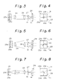
- FIGs. 3 to 8 show, in a simplified fashion, the optical path from the recording surface 25 of the recording medium to the servo error detection optical system.
- the rays of light emitted from the semiconductor laser are focused by the objective 24 on the recording surface 25 of the recording medium in the form of a beam spot.
- the light is reflected by the recording surface 25 of the recording medium, it possesses information, and the light having information passes through the objective 24, the condenser 26 and the cylindrical lens 27 in that order and thereby exhibits astigmatism.
- This light is received by the light detector 28 having four light receiving portions 28a, 28b, 28c and 28d which are divided by the two boundary lines inclined by 45° relative to the generatrix of the cylindrical lens 27.
- a beam spot 42 formed on the photo detector 28 is circular, as shown in Fig. 4.
- the photo detector 28 detects a beam spot 42 which is elongated in a direction b0 which is parallel to the generatrix of the cylindrical lens 27, as shown in Fig. 6. In consequence, FES ⁇ 0.
- the photo detector 28 detects an elliptical beam spot 42 which is elongated in a direction a0 which is perpendicular to the generatrix of the cylindrical lens 27, as shown in Fig. 8. In consequence, FES > 0.
- This type of focusing error signal detection method is called the astigmatism method.
- the beam spot formed on the photo detector 28 has a shadow portion 43 (hereinafter referred to as a diffraction pattern) due to a diffraction caused by an information track 25a, as shown in Figs. 9 to 14.
- This diffraction pattern 43 occurs even when the beam of light is in focus, as shown in Figs. 3 and 4.
- the diffraction pattern 43 varies, as shown in Figs. 10, 12 and 14, in accordance with a shift in the positional relation between a beam spot 41 formed on the recording surface 25 of the recording medium and the information track 25a, a guide track 25b, as shown in Figs. 9, 11 and 13 respectively.
- the corresponding diffraction pattern 43 is symmetrical with respect to the line X - X which separates the light receiving portions 28a and 28b from the light receiving portions 28d and 28c, as shown in Figs 12.
- TES 0.
- the corresponding diffraction pattern 43 shows asymmetry. In consequence, TES ⁇ 0.
- the polarization beam splitter 23 is mounted on a housing in a state in which it is elastically supported by a spring or in which it is fixed by an adhesive.
- a position or an angle at which the polarization beam splitter 23 is mounted may change with time due to the changes in the temperature or various other factors associated with the mounting precision of the polarization beam splitter 23.
- the optical axis of the rays of light which are directed toward the servo error signal detection optical system inclines at an angle 2 ⁇ which is twice the angle ⁇ , as shown by the virtual line.
- the beam spot formed on the photo detector 28 deviates, and a great offset occurs in the servo error signal, thereby the accurate recording and reproducing of the data become difficult to be performed.
- an object of the present invention to provide an optical head capable of minimizing a shift in the optical axis of the rays of light directed toward a servo error signal detection optical system even at a time when a position or an angle of a light split unit is changed with a time due to the changes in the temperature or the various other factors.
- An object of the present invention can be achieved by an optical head for an optical disk recording/reproducing apparatus, which is capable of irradiating a recording medium by a light beam emitted from a light source and introducing an information light which is formed by the light beam reflected from the recording medium to a photo detecting system with minimizing a shift of an optical axis of the information light, the optical head includes a unit for receiving the information light which is reflected from the recording medium, a first reflecting unit for reflecting the information light received by the receiving unit, a second reflecting unit for reflecting the information light reflected by the first reflecting unit and for directing the reflected information light toward the photo detecting system, and a unit for emerging the information light reflected by the second reflecting unit to the photo detecting system.
- the first reflecting unit has a surface for reflecting the information light thereby
- the second reflecting unit also has a surface for reflecting the reflected information light from the surface of the first reflecting unit, the surface of the first reflecting unit being substantially parallel to the surface of the second reflecting unit.
- the emerging surface has a surface for emerging the information light reflected by the surface of the second reflecting unit, and an angle between the surface of the receiving unit and the surface of the first reflecting unit substantially being coincided with an angle between the surface of the second reflecting unit and the surface of the emerging unit.
- the receiving unit, the first reflecting unit, the second reflecting unit and the emerging unit constitutes a light split unit, preferably.
- the beam split unit further includes a beam incident unit disposed adjacent to the first reflecting unit for shaping a beam of the light incident on a surface thereof.
- a modified Wollaston prism is disposed on the surface of the emerging unit for splitting the information light emerged from the emerging unit.
- the modified Wollaston prism preferably splits the information light emerged from the emerging unit into three components.
- the three components are a central beam whose intensity is the same as that of the incident light received by the receiving unit, a left and a right beams each of whose intensities is varied in accordance with a polarized state of the incident light, preferably.
- a modified Wollaston prism is disposed between the first reflecting unit and the second reflecting unit for splitting the information light emerged from the emerging unit.
- the optical head further includes a photo detector for monitoring an intensity of the light emitted from the light source and incident on the beam incident unit, preferably.
- the photo detecting system consists of a condense lens, a cylindrical lens, and a photo detector in series for detecting a focusing error signal by an astigmatism and a tracking error signal by a push-pull from a light passing therethrough.
- the optical head further includes a signal detecting system consisting of a halfwave length plate, a condense lens, a polarizer, and a pair of photo detectors, in series for obtaining a high quality of a read signal.
- a signal detecting system consisting of a halfwave length plate, a condense lens, a polarizer, and a pair of photo detectors, in series for obtaining a high quality of a read signal.
- the light reflected from the recording medium is polarized thereby.
- the light splitting unit is a polarization beam splitter.
- the information light is so formed that a plane of polarization thereof is rotated in a direction corresponding to a direction in which an area of a surface of the recording medium irradiated by a spot of the beam light is magnetized, preferably.
- the optical axis of the information light which leave the light split unit from an information light emerging surface thereof coincides with that of incident light. Also, even at a time when the angle of the light split unit shifts, the optical axis of the information light which leave the light split unit from an information light emerging surface thereof does not separate from the optical axis of the incident light greatly although offset occurs more or less. In consequence, displacement of the optical axis of the information light which are directed toward the servo error signal detection optical system can be minimized.
- a modified Wollaston prism is integrally formed between first and second information light reflecting surfaces. In consequence, the overall size of the optical head can be reduced.
- the first embodiment relates to an optical head which does not employ a modified Wollaston prism.
- linearly polarized rays of light which are emitted from a semiconductor laser 51 are converted into parallel rays of light by a collimator 52.
- the parallel rays of light pass through a polarization beam splitter (light split unit) 53 and is focused and irradiated by an objective 54 on a recording surface 55 of an optical magnetic recording medium in the form of a beam spot.
- the rays of light are reflected by the recording surface 55 of the recording medium, they are modulated such that the plane of polarization thereof is rotated in a direction corresponding to the direction in which the area of the recording surface 55 irradiated by the beam spot is magnetized and become information light.
- This modulated information light passes through the objective 54 again and is then made incident on the polarization beam splitter 53 from an information light incident surface 53a thereof.
- the incident light is reflected by a first information light reflecting surface 53b and then propagates in a direction indicated by A1.
- the rays of light which propagate in the direction indicated by Al are split into two components by a splitting surface 53c′, that is, the component directed in a direction indicated by B1 and the component directed in a direction indicated by B2.
- the rays of light which are directed in the direction indicated by B1 are reflected by a second information light reflecting surface 53c which is solely used to reflect light, and then propagate in a direction indicated by C1.
- the rays of light then emerge from the polarization beam splitter 53 through an information light emerging surface 53d, and reaches a servo error signal detection optical system which consists of a condenser 56, a cylindrical lens 57 and a photo detector 58.
- the servo error signal detection optical system detects a focusing error signal by the astigmatism method and a tracking error signal by the push-pull method from the rays of light which pass through it.
- the polarization beam splitter 53 is arranged such that the first information light reflecting surface 53b is substantially parallel to the second information light reflecting surface 53c, and such that the angle between the information light incident surface 53a and the first information light reflecting surface 53b substantially coincides with the angle between the second information light reflecting surface 53c and the information light emerging surface 53d. Furthermore, the information light incident surface 53a, the first information light reflecting surface 53b, the second information light reflecting surface 53c and the information light emerging surface 53d are integrally formed in the beam splitter 53.
- the rays of light which are directed in the direction indicated by B2 emerges from the polarization beam splitter 53 through a surface 53d′ thereof, and is then demodulated by a read signal detection optical system which consists of a halfwave plate 59, a condenser 60, a polarization beam splitter (polarizer) 61, and a pair of photo detectors 62 and 63.
- the read signal detection optical system includes two photo detectors 62 and 63 so that the noises having the same phase can be cancelled by operating the differential output of these two photo detectors 62, 63 and a read signal having a high quality can thus be obtained.
- the principle of the minimization will be explained below with reference to Figs. 18 and 19.
- the light having information obtained when the light is reflected by the recording surface 55 of the recording medium passes through the objective 54 and is then made incident on the polarization beam splitter 53 from the information light incident surface 53a.
- the incident light is first reflected by the first information light reflecting surface 53b and then by the second information light reflecting surface 53c, and leaves the polarization beam splitter 53 from the information light emerging surface 53d.
- the polarization beam splitter 53 is deviated upward by a distance ⁇ d and located at a position indicated by a virtual line, as shown in Fig. 18, the rays of light reflected by the first information light reflecting surface 53b deviate upward by the distance ⁇ d, as shown by the virtual line.
- the rays of light reflected by the second information light reflecting surface 53c coincide with the optical axis of the normal rays of light indicated by the solid line and thus maintain the optical axis of the normal rays of light.
- the rays of light reflected by the first information light reflecting surface 53b inclines by an angle 2 ⁇ relative to the optical axis of the normal rays of light indicated by the solid line and thereby separate from the optical axis of the normal rays of light.
- the rays of light reflected by the second information light reflecting surface 53c do not separate from the optical axis of the normal rays of light although offset occurs more or less. In consequence, displacement of the optical axis of the rays of light directed toward the servo error signal detection optical system can be minimized.
- a second embodiment of the present invention will be described below with reference to Fig. 20.
- the same reference numerals are used to denote parts which are the same as those in the first embodiment, description thereof being omitted.
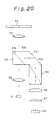
- the second embodiment relates to an optical head which employs a modified Wollaston prism to split rays of light.
- the following two embodiments of the present invention will also employ the modified Wollaston prism.
- the polarization beam splitter 53 is also arranged, like the one employed in the first embodiment, such that the first information light reflecting surface 53b is substantially parallel to the second information light reflecting surface 53c, and such that the angle between the information light incident surface 53a and the first information light reflecting surface 53b substantially coincides with the angle between the second information light reflecting surface 53c and the information light emerging surface 53d. Furthermore, the information light incident surface 53a, the first information light reflecting surface 53b, the second information light reflecting surface 53c and the information light emerging surface 53d are integrally formed in the beam splitter 53.
- a modified Wollaston prism is integrally disposed on the information light emerging surface 53d of the polarization beam splitter 53.
- the information light which emerges from the information light emerging surface 53d is made incident on the modified Wollaston prism 64, and is split into three components by the Wollaston prism 64, including the central beam whose intensity remains the same as that of the incident light and a left and a right beams, each of whose intensity is varied in accordance with the polarized state of the incident light.
- the photo detector 58 consists of six elements in which four parts correspond to the central beam while two elements correspond to the right and left beams respectively.
- the three beams emerged from the Wollaston prism 64 are transformed into rays of beam exhibiting astigmatism while they pass through the condenser 56 and the cylindrical lens 57.
- a servo error signal is detected from the output of the four elements corresponding to the central beam, and a read signal is detected by operating the differential output of the remaining two elements.
- the single optical system can be used as both the servo error signal detection optical system and the read signal detection optical system, and the photo detector can be constructed by one component which has the six elements.
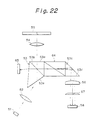
- the modified Wollaston prism 64 is integrally disposed between the first information light reflecting surface 53b and the second information light reflecting surface 53c, as shown in Figs. 21 and 22. Even though the polarization beam splitter 53 is divided by the modified Wollaston prism 64, it is arranged such that the first information light reflecting surface 53b is substantially parallel to the second information light reflecting surface 53c, and such that the angle between the information light incident surface 53a and the first information light reflecting surface 53b substantially coincides with the angle between the second information light reflecting surface 53c and the information light emerging surface 53d. Furthermore, the information light incident surface 53a, the first information light reflecting surface 53b, the second information light reflecting surface 53c and the information light emerging surface 53d are integrally formed in the beam splitter 53.
- the modified Wollaston prism 64 does not project downward, unlike the one employed in the second embodiment. In consequence, the overall height of the optical head can be reduced.
- An optical head shown in Fig. 22 differs from the one shown in Fig. 21 in that a beam incident surface 53e of the polarization beam splitter 53 has the function of shaping a beam of light. In this way, light utilizing efficiency and spot performance can be improved.
- a beam of light which is incident on the polarization beam splitter 53 from the beam incident surface 53e is partially reflected by the first information light reflecting surface 53b and then made incident on a photo detector 65 for a monitor.
- the photo detector 65 for the monitor controls the intensity of light emitted from the semiconductor laser 51.
- any of the above-described embodiments of the present invention has a configuration which is constructed on a plane.
- the present invention is also applicable to a separate type optical head in which an optical axis is deflected by 90° by a deflection mirror disposed below the objective 54 and in which the objective 54 and the deflection mirror are together moved in a radial direction of a disk (not shown).
Landscapes
- Physics & Mathematics (AREA)
- Optics & Photonics (AREA)
- Optical Head (AREA)
- Optical Recording Or Reproduction (AREA)
Applications Claiming Priority (2)
| Application Number | Priority Date | Filing Date | Title |
|---|---|---|---|
| JP239009/89 | 1989-09-14 | ||
| JP1239009A JP2902415B2 (ja) | 1989-09-14 | 1989-09-14 | 光学ヘッド |
Publications (3)
| Publication Number | Publication Date |
|---|---|
| EP0418087A2 true EP0418087A2 (de) | 1991-03-20 |
| EP0418087A3 EP0418087A3 (en) | 1992-01-22 |
| EP0418087B1 EP0418087B1 (de) | 1995-11-15 |
Family
ID=17038539
Family Applications (1)
| Application Number | Title | Priority Date | Filing Date |
|---|---|---|---|
| EP90310047A Expired - Lifetime EP0418087B1 (de) | 1989-09-14 | 1990-09-13 | Optischer Kopf |
Country Status (5)
| Country | Link |
|---|---|
| US (1) | US5189655A (de) |
| EP (1) | EP0418087B1 (de) |
| JP (1) | JP2902415B2 (de) |
| CA (1) | CA2025311C (de) |
| DE (1) | DE69023585T2 (de) |
Cited By (2)
| Publication number | Priority date | Publication date | Assignee | Title |
|---|---|---|---|---|
| EP0539128A3 (en) * | 1991-10-22 | 1993-06-30 | Canon Kabushiki Kaisha | Plural-beam optical head |
| DE19645110A1 (de) * | 1996-11-01 | 1998-05-07 | Thomson Brandt Gmbh | Aufzeichnungs- oder Wiedergabegerät und Verfahren zum Erkennen eines Fokussierungszustands |
Families Citing this family (31)
| Publication number | Priority date | Publication date | Assignee | Title |
|---|---|---|---|---|
| JPH03116567A (ja) * | 1989-09-29 | 1991-05-17 | Canon Inc | 光磁気情報再生装置 |
| EP0475765B1 (de) * | 1990-09-13 | 1996-12-11 | Canon Kabushiki Kaisha | Optischer Kopf für magnetooptisches Aufzeichnungs-/Wiedergabegerät |
| US5244775A (en) * | 1991-03-20 | 1993-09-14 | Hitachi, Ltd. | Method of manufacturing an optical disc |
| JPH05109143A (ja) * | 1991-10-18 | 1993-04-30 | Sony Corp | 光学ピツクアツプ装置 |
| US5559639A (en) * | 1992-04-20 | 1996-09-24 | Asahi Kogaku Kogyo Kabushiki Kaisha | Beam receiving position adjusting device |
| KR100230227B1 (ko) * | 1993-04-30 | 1999-11-15 | 윤종용 | 광픽업 |
| DE4317190B4 (de) * | 1993-05-22 | 2005-12-22 | Deutsche Thomson-Brandt Gmbh | Fehlerratenverringerung |
| KR950013702B1 (ko) * | 1993-07-15 | 1995-11-13 | 엘지전자주식회사 | 광자기 디스크의 광픽업 장치 |
| JP3541893B2 (ja) * | 1993-08-06 | 2004-07-14 | ソニー株式会社 | 光磁気記録媒体再生装置 |
| JP3449769B2 (ja) * | 1993-12-29 | 2003-09-22 | ソニー株式会社 | 光ピックアップ装置 |
| US5495466A (en) * | 1994-01-10 | 1996-02-27 | Eastman Kodak Company | Write verification in an optical recording system by sensing mark formation while writing |
| KR970000645B1 (ko) * | 1994-02-26 | 1997-01-16 | 엘지전자 주식회사 | 광픽업 시스템 |
| KR100230233B1 (ko) * | 1994-06-30 | 1999-11-15 | 윤종용 | 포커스에러 검출장치 |
| US5541906A (en) * | 1994-07-29 | 1996-07-30 | Olympus Optical Co., Ltd. | Optical head for magneto-optical record medium |
| JP3374573B2 (ja) * | 1995-02-20 | 2003-02-04 | 松下電器産業株式会社 | 光ピックアップ及び光ガイド部材 |
| JP3626003B2 (ja) * | 1997-10-06 | 2005-03-02 | 富士通株式会社 | 光学的情報記憶装置 |
| JP3382846B2 (ja) * | 1998-05-11 | 2003-03-04 | 日本電気株式会社 | 光ヘッド及び光ヘッドに於ける光源出力のモニター方法 |
| JP2000021001A (ja) * | 1998-06-30 | 2000-01-21 | Pioneer Electron Corp | 光ピックアップ装置 |
| JP3607836B2 (ja) * | 1999-03-31 | 2005-01-05 | シャープ株式会社 | 光ピックアップ装置 |
| DE10214775A1 (de) * | 2002-04-03 | 2003-10-16 | Thomson Brandt Gmbh | Vorrichtung zur Korrektur von Signalmodulationen |
| JP4251107B2 (ja) * | 2003-05-30 | 2009-04-08 | ソニー株式会社 | 光学ヘッド及びこれを用いた記録及び/又は再生装置 |
| TWI276094B (en) * | 2004-03-12 | 2007-03-11 | Hon Hai Prec Ind Co Ltd | Optical reading/writing device |
| TWI302307B (en) * | 2004-04-09 | 2008-10-21 | Hon Hai Prec Ind Co Ltd | Optical reading/writing system |
| TWI302308B (en) * | 2004-04-23 | 2008-10-21 | Hon Hai Prec Ind Co Ltd | Optical reading/writing system |
| TWI273586B (en) * | 2004-06-11 | 2007-02-11 | Hon Hai Prec Ind Co Ltd | Optical recording/reproducing system |
| TWI275084B (en) | 2004-07-09 | 2007-03-01 | Hon Hai Prec Ind Co Ltd | Optical reading/recording system |
| TWI260616B (en) * | 2004-07-09 | 2006-08-21 | Hon Hai Prec Ind Co Ltd | Optical reading/recording system |
| TWI284895B (en) * | 2004-07-16 | 2007-08-01 | Hon Hai Prec Ind Co Ltd | Optical reading/recording system |
| TWI329869B (en) * | 2004-11-05 | 2010-09-01 | Hon Hai Prec Ind Co Ltd | Semiconductor laser assembly and optical pickup device using the same |
| TWI287222B (en) * | 2004-11-12 | 2007-09-21 | Hon Hai Prec Ind Co Ltd | Optical pickup device |
| US8456637B2 (en) * | 2010-08-26 | 2013-06-04 | Mitutoyo Corporation | Multiple measuring point configuration for a chromatic point sensor |
Family Cites Families (16)
| Publication number | Priority date | Publication date | Assignee | Title |
|---|---|---|---|---|
| JPS6043240A (ja) * | 1983-08-19 | 1985-03-07 | Mitsubishi Electric Corp | 光学的信号読出装置 |
| JPS60143453A (ja) * | 1983-12-28 | 1985-07-29 | Olympus Optical Co Ltd | 光学式情報記録再生用ピツクアツプ装置 |
| JPS61104348A (ja) * | 1984-10-22 | 1986-05-22 | Nec Corp | 光磁気ヘツド |
| DE3665372D1 (en) * | 1985-05-31 | 1989-10-05 | Siemens Ag | Optical system for guiding the read-out beam in a magneto-optical memory |
| CA1319194C (en) * | 1986-07-28 | 1993-06-15 | Hideaki Satou | Focusing error detector and optical data detecting device incorporating the focusing error detector |
| JPH039134Y2 (de) * | 1986-08-05 | 1991-03-07 | ||
| JPS63113503A (ja) * | 1986-10-31 | 1988-05-18 | Toyo Commun Equip Co Ltd | ウオ−ラストンプリズム |
| JPH0677351B2 (ja) * | 1986-11-15 | 1994-09-28 | ソニー株式会社 | 光学ピツクアツプ装置 |
| US4951274A (en) * | 1987-01-23 | 1990-08-21 | Nec Corporation | Magneto-optical head capable of separating beams for reading recorded information and servo information by use of one optical element |
| JPS63187440A (ja) * | 1987-01-29 | 1988-08-03 | Nec Corp | 光学ヘツド |
| DE3802538A1 (de) * | 1987-01-28 | 1988-08-11 | Olympus Optical Co | Vorrichtung zum erfassen von fotomagnetischen signalen |
| JP2618391B2 (ja) * | 1987-04-28 | 1997-06-11 | シャープ株式会社 | 光ピツクアツプ |
| JPS6427057A (en) * | 1987-07-22 | 1989-01-30 | Nec Corp | Optical head device for magneto-optical recording |
| JPS6431513U (de) * | 1987-08-17 | 1989-02-27 | ||
| US5060212A (en) * | 1987-08-17 | 1991-10-22 | Ricoh Company, Ltd. | Integrated optical pick-up device |
| US5070494A (en) * | 1988-04-05 | 1991-12-03 | Ricoh Company, Ltd. | Optical pickup device with dual-mode drive mechanism |
-
1989
- 1989-09-14 JP JP1239009A patent/JP2902415B2/ja not_active Expired - Lifetime
-
1990
- 1990-09-11 US US07/580,830 patent/US5189655A/en not_active Expired - Lifetime
- 1990-09-13 EP EP90310047A patent/EP0418087B1/de not_active Expired - Lifetime
- 1990-09-13 CA CA002025311A patent/CA2025311C/en not_active Expired - Fee Related
- 1990-09-13 DE DE69023585T patent/DE69023585T2/de not_active Expired - Fee Related
Cited By (4)
| Publication number | Priority date | Publication date | Assignee | Title |
|---|---|---|---|---|
| EP0539128A3 (en) * | 1991-10-22 | 1993-06-30 | Canon Kabushiki Kaisha | Plural-beam optical head |
| US5434841A (en) * | 1991-10-22 | 1995-07-18 | Canon Kabushiki Kaisha | Plural-beam optical head |
| DE19645110A1 (de) * | 1996-11-01 | 1998-05-07 | Thomson Brandt Gmbh | Aufzeichnungs- oder Wiedergabegerät und Verfahren zum Erkennen eines Fokussierungszustands |
| US6249493B1 (en) | 1996-11-01 | 2001-06-19 | Deutsche Thomson-Brandt Gmbh | Recording or replay device and method for recognition of a focussing status |
Also Published As
| Publication number | Publication date |
|---|---|
| DE69023585D1 (de) | 1995-12-21 |
| DE69023585T2 (de) | 1996-05-15 |
| JP2902415B2 (ja) | 1999-06-07 |
| US5189655A (en) | 1993-02-23 |
| CA2025311A1 (en) | 1991-03-15 |
| CA2025311C (en) | 1996-03-05 |
| EP0418087A3 (en) | 1992-01-22 |
| EP0418087B1 (de) | 1995-11-15 |
| JPH03102647A (ja) | 1991-04-30 |
Similar Documents
| Publication | Publication Date | Title |
|---|---|---|
| US5189655A (en) | Optical head for optical disk recording/reproducing apparatus including modified wollaston prism | |
| US4715024A (en) | Optical head with provision for tracking and focussing control | |
| JP2725632B2 (ja) | 光ヘッド装置 | |
| US4817074A (en) | Method and apparatus for detecting the focusing state and positioning accuracy of a light beam directed onto an optical disk tracking guide in an optical recording system | |
| US4695992A (en) | Optical information recording-reproducing apparatus in which the relative position of a primary beam and secondary beams on recording medium is varied during recording and reproduction of information | |
| US4977552A (en) | Split type optical pick-up device with a tracking error detector on the moving part | |
| US5606542A (en) | Optical pickup using three beam tracking method | |
| US5150350A (en) | Magneto-optical data recording and reproducing device | |
| EP0558249B1 (de) | Gerät zur Aufzeichnung/Wiedergabe von optischen Informationen | |
| US5132959A (en) | Optical head in use with an optical recording/reproducing apparatus | |
| US5777974A (en) | Optical head and magneto-optical reproducing apparatus using the same | |
| JPH06195728A (ja) | 光学ヘッド | |
| US5708642A (en) | Optical head device with lens system for increasing beam diameter of light to be incident on objective lens | |
| KR0141268B1 (ko) | 광디스크 기록/재생장치의 광헤드 | |
| JP2629456B2 (ja) | 対物レンズ位置検出装置 | |
| JP2812764B2 (ja) | 光ディスク装置用光学ヘッド | |
| JPH0244534A (ja) | 光ピツクアツプ装置 | |
| JPH08338904A (ja) | 光学素子及び光学的情報記録再生装置 | |
| JP2795238B2 (ja) | ディスク記録再生装置 | |
| US4868821A (en) | Optical pickup which includes a single objective lens having magnification equal to or greater than 3 and equal to or smaller than 5 | |
| US5532477A (en) | Optical pickup apparatus having lens group for determining paths of an incident beam and a reflected & beam | |
| JPH0227736B2 (de) | ||
| CN1187004A (zh) | 双焦光学头装置 | |
| JPH0242647A (ja) | 光ピツクアツプ装置 | |
| JPH0210489B2 (de) |
Legal Events
| Date | Code | Title | Description |
|---|---|---|---|
| PUAI | Public reference made under article 153(3) epc to a published international application that has entered the european phase |
Free format text: ORIGINAL CODE: 0009012 |
|
| 17P | Request for examination filed |
Effective date: 19901220 |
|
| AK | Designated contracting states |
Kind code of ref document: A2 Designated state(s): DE FR GB NL |
|
| PUAL | Search report despatched |
Free format text: ORIGINAL CODE: 0009013 |
|
| AK | Designated contracting states |
Kind code of ref document: A3 Designated state(s): DE FR GB NL |
|
| 17Q | First examination report despatched |
Effective date: 19940225 |
|
| GRAA | (expected) grant |
Free format text: ORIGINAL CODE: 0009210 |
|
| AK | Designated contracting states |
Kind code of ref document: B1 Designated state(s): DE FR GB NL |
|
| REF | Corresponds to: |
Ref document number: 69023585 Country of ref document: DE Date of ref document: 19951221 |
|
| ET | Fr: translation filed | ||
| PLBE | No opposition filed within time limit |
Free format text: ORIGINAL CODE: 0009261 |
|
| STAA | Information on the status of an ep patent application or granted ep patent |
Free format text: STATUS: NO OPPOSITION FILED WITHIN TIME LIMIT |
|
| 26N | No opposition filed | ||
| REG | Reference to a national code |
Ref country code: GB Ref legal event code: IF02 |
|
| PGFP | Annual fee paid to national office [announced via postgrant information from national office to epo] |
Ref country code: FR Payment date: 20050823 Year of fee payment: 16 |
|
| PGFP | Annual fee paid to national office [announced via postgrant information from national office to epo] |
Ref country code: GB Payment date: 20050907 Year of fee payment: 16 |
|
| PGFP | Annual fee paid to national office [announced via postgrant information from national office to epo] |
Ref country code: DE Payment date: 20050909 Year of fee payment: 16 |
|
| PGFP | Annual fee paid to national office [announced via postgrant information from national office to epo] |
Ref country code: NL Payment date: 20050915 Year of fee payment: 16 |
|
| PG25 | Lapsed in a contracting state [announced via postgrant information from national office to epo] |
Ref country code: NL Free format text: LAPSE BECAUSE OF NON-PAYMENT OF DUE FEES Effective date: 20070401 |
|
| PG25 | Lapsed in a contracting state [announced via postgrant information from national office to epo] |
Ref country code: DE Free format text: LAPSE BECAUSE OF NON-PAYMENT OF DUE FEES Effective date: 20070403 |
|
| GBPC | Gb: european patent ceased through non-payment of renewal fee |
Effective date: 20060913 |
|
| NLV4 | Nl: lapsed or anulled due to non-payment of the annual fee |
Effective date: 20070401 |
|
| REG | Reference to a national code |
Ref country code: FR Ref legal event code: ST Effective date: 20070531 |
|
| PG25 | Lapsed in a contracting state [announced via postgrant information from national office to epo] |
Ref country code: GB Free format text: LAPSE BECAUSE OF NON-PAYMENT OF DUE FEES Effective date: 20060913 |
|
| PG25 | Lapsed in a contracting state [announced via postgrant information from national office to epo] |
Ref country code: FR Free format text: LAPSE BECAUSE OF NON-PAYMENT OF DUE FEES Effective date: 20061002 |