EP0418089A1 - Dispositif pour activer le chauffage - Google Patents
Dispositif pour activer le chauffage Download PDFInfo
- Publication number
- EP0418089A1 EP0418089A1 EP90310055A EP90310055A EP0418089A1 EP 0418089 A1 EP0418089 A1 EP 0418089A1 EP 90310055 A EP90310055 A EP 90310055A EP 90310055 A EP90310055 A EP 90310055A EP 0418089 A1 EP0418089 A1 EP 0418089A1
- Authority
- EP
- European Patent Office
- Prior art keywords
- heater
- voltage
- activating apparatus
- current regulating
- regulating element
- Prior art date
- Legal status (The legal status is an assumption and is not a legal conclusion. Google has not performed a legal analysis and makes no representation as to the accuracy of the status listed.)
- Granted
Links
- 230000003213 activating effect Effects 0.000 title claims abstract description 29
- 230000001105 regulatory effect Effects 0.000 claims abstract description 15
- 229910052736 halogen Inorganic materials 0.000 claims description 6
- 150000002367 halogens Chemical class 0.000 claims description 6
- 238000010438 heat treatment Methods 0.000 claims description 4
- 230000001052 transient effect Effects 0.000 claims 2
- 230000001276 controlling effect Effects 0.000 description 8
- 230000003247 decreasing effect Effects 0.000 description 4
- 230000004075 alteration Effects 0.000 description 1
- 210000000078 claw Anatomy 0.000 description 1
- 238000004140 cleaning Methods 0.000 description 1
- 230000004048 modification Effects 0.000 description 1
- 238000012986 modification Methods 0.000 description 1
- 230000003287 optical effect Effects 0.000 description 1
Images



Classifications
-
- G—PHYSICS
- G05—CONTROLLING; REGULATING
- G05D—SYSTEMS FOR CONTROLLING OR REGULATING NON-ELECTRIC VARIABLES
- G05D23/00—Control of temperature
- G05D23/19—Control of temperature characterised by the use of electric means
- G05D23/20—Control of temperature characterised by the use of electric means with sensing elements having variation of electric or magnetic properties with change of temperature
- G05D23/24—Control of temperature characterised by the use of electric means with sensing elements having variation of electric or magnetic properties with change of temperature the sensing element having a resistance varying with temperature, e.g. a thermistor
-
- G—PHYSICS
- G05—CONTROLLING; REGULATING
- G05D—SYSTEMS FOR CONTROLLING OR REGULATING NON-ELECTRIC VARIABLES
- G05D23/00—Control of temperature
- G05D23/19—Control of temperature characterised by the use of electric means
- G05D23/1906—Control of temperature characterised by the use of electric means using an analogue comparing device
- G05D23/1909—Control of temperature characterised by the use of electric means using an analogue comparing device whose output amplitude can only take two discrete values
-
- Y—GENERAL TAGGING OF NEW TECHNOLOGICAL DEVELOPMENTS; GENERAL TAGGING OF CROSS-SECTIONAL TECHNOLOGIES SPANNING OVER SEVERAL SECTIONS OF THE IPC; TECHNICAL SUBJECTS COVERED BY FORMER USPC CROSS-REFERENCE ART COLLECTIONS [XRACs] AND DIGESTS
- Y10—TECHNICAL SUBJECTS COVERED BY FORMER USPC
- Y10S—TECHNICAL SUBJECTS COVERED BY FORMER USPC CROSS-REFERENCE ART COLLECTIONS [XRACs] AND DIGESTS
- Y10S323/00—Electricity: power supply or regulation systems
- Y10S323/908—Inrush current limiters
Definitions
- the present invention relates to a heater activating apparatus for activating a heater such as a halogen heater and the like, and more particularly, it relates to a heater activating apparatus for activating a heater so that a heating element heated by the heater is maintained at a predetermined temperature.
- a heat fixing device wherein a toner image is heated or heated and pressurized by a heating element such as a heat roller which surface is maintained at a predetermined temperature has widely been used.
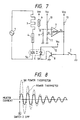
- FIG. 7 An example of a heater activating circuit which is used with such heat fixing device and which provides a background of the present invention is shown in Fig. 7.
- the switch 2 When the switch 2 is turned ON, the voltage V3 becomes a GND level (i.e., earthed), the transistor 8 becomes an OFF condition, and a light emitting element 5b of the SSR 5 also becomes an OFF condition. Since a triac 5a of the SSR 5 is in an OFF condition when the light emitting element 5b is turned OFF, the voltage is not applied to the heater.
- a GND level i.e., earthed
- the transistor 8 becomes an OFF condition
- a light emitting element 5b of the SSR 5 also becomes an OFF condition. Since a triac 5a of the SSR 5 is in an OFF condition when the light emitting element 5b is turned OFF, the voltage is not applied to the heater.
- the voltage V1 is determined by the partial voltage of the resistor 9 and the temperature detecting thermistor 6. That is to say, when the temperature of the thermistor 6 is decreased the value of V1 is reduced, and, when the temperature of the thermistor 6 is increased the value of V1 is also increased. If the voltage V1 is lower than a voltage V2 of the other input terminal of the comparator 7, the output V3 of the comparator 7 will be HIGH. In this case, since the transistor 8 is turned ON, the light emitting element 5b is also turned ON.
- the triac 5a Since the SSR 5 is zerocross-controlled, after the light emitting element 5b has been turned ON, the triac 5a is turned ON when the voltage at both ends thereof become zero or thereabout. And, the triac 5a is maintained in the ON condition until the voltage of the power surce becomes zero or thereabout (i.e., the current in the heater becomes zero) after the light emitting element 5b has been turned OFF.
- the temperature of the thermistor 6 increases to increase the voltage V1 higher than the voltage V2.
- the comparator 7 is inverted to provide a LOW output. Consequently, the transistor 8 is turned OFF, thereby deenergizing the heater 3.
- Such condition is shown in Fig. 10.
- A indicates a time point when the temperature adjustment is initiated by turning the switch 2 OFF in a condition that the temperatures of the heater 3, power thermistor 4 and the temperature detecting thermistor 6 are reduced to a room temperature; and B indicates a time point when the heater 3 is energized in a condition that the heater 3 is controlled substantially at the set temperature and the temperature of the temperature detecting thermistor 6 is substantially in the set value.
- the heater current in the time point A is shown in Fig. 8
- the heater current in the time point B is shown in Fig. 9.
- the power thermistor 4 is used to control the rush current to the heater.
- the power thermistor has the resistance of a few ohms when the temperature of the power thermistor itself is cooled to the room temperature. However, when the power thermistor is heated by the heater current, the resistance thereof is reduced below one ohm, thereby reducing the power consumption.
- An object of the present invention is to provide a heater activating apparatus which can provide a rush current control to a heater for a long time.
- Another object of the present invention is to provide a heater activating apparatus which can suppress the increase in temperature of a current controlling element.
- a further object of the present invention is to provide a heater activating apparatus wherein the energization of a heater without through a current controlling element and the energization of the heater through the current controlling element can be selectively utilized.
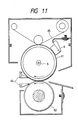
- Fig. 11 is a sectional view of a heat fixing device using a heater activating apparatus according to the present invention.
- the reference numeral 61 denotes a heat roller including a halogen heater 3 therein; 62 denotes a pressure roller urged against the heat roller 61 to form a nip therebetween; 64 denotes a separating claw for separating a recording medium or recording sheet; 65 denotes a web for cleaning a surface of the heat roller and for applying the separating agent to the surface of the heat roller; and 6 denotes a thermistor for detecting a surface temperature of the heat roller 61. On the basis of the detction output from the thermistor 6, by energizing or disenergizing the halogen heater 3, the surface of the heat roller 61 is maintained at a predetermined temperature.
- the recording sheet on which an unfixed toner image is born is pinched by the nip between the heat roller 61 and the pressure roller 62 and is passed through the nip; meanwhile, the toner image is fixed to the recording sheet by heat and pressure.
- Fig. 1 shows a circuit of the heater activating portion.
- Fig. 2 shows voltage waves illustrating an example of the changes in voltage of various parts of the circuit of Fig. 1, regarding the time elapsed.
- the heater 3 When the temperature of the temperature detecting thermistor 6 is high and the voltage V1 is higher than the voltage V2, the heater 3 remains in the OFF condition; however, if the temperature of the temperature detecting thermistor 6 is decreased and the voltage V1 becomes lower than the voltage V2, the comparator 7 outputs the LOW level signal.
- the one-shot timer 22 outputs a LOW pulse having a width or duration t2 starting from the edge of the building-up wave of the voltage V4. Since the voltage V6 corresponds to the inversion of the voltage V5 inverted in the inverter 23, the voltage V6 has a HIGH pulse having a width t2 starting from the edge of the building-up wave of the voltage V4.
- the voltage V7 Since the voltage V7 is obtained by the voltages V4 and V6 treated by the OR gate, the voltage V7 becomes a LOW level at the edge of the building-up wave of the voltage V6, and returns a HIGH level at the edge of the building-up wave of the voltage V4.
- the voltage V8 becomes a LOW pulse having a width t2 starting from the edge of the building-up wave of the voltage V4, similar to the voltage V5.
- the transistor 26 is turned OFF to energize a light emitting element 21b, thus turning a triac 21a ON.
- the transistor 27 is turned OFF to energize a light emitting element 5b, thus turning a triac 5a ON. That is to say, during the turn-on time t1, since the triac 5a is turned ON for the initial time duration t2, the voltage from the power source 1 is applied to the heater 3 through the large electric power thermistor 4 having the resistance of negative temperature feature. After the time duration t2, since the triac 5a is turned OFF and the triac 21a turned ON, the power thermistor 4 and the triac 5a are short-circuited not to flow the current therethrough, with the result that all of the voltage of the power source 1 is applied to the heater 3. That is to say, the power thermistor is connected to the heater in series for a time duration required to prevent the rush current to the heater.
- Fig. 3 shows the rush current control effected when the switch 2 is turned from ON to OFF in a condition that all of the elements are in the room temperature.
- the rush current to the heater is sufficiently suppressed.
- the triac 21a is turned ON to short-circuit the power thermistor 4 and the triac 5a, the current is increased; however, in this point, since the heater 3 has already been heated considerably, the amount of the current increased by releasing the power thermistor 4 is a little.
- a heater activating apparatus according a second embodiment of the present invention is shown in Fig. 5.
- the reference numeral 41 denotes a power resistor
- 42, 43 denote zerocross-controlled SSRs
- 44, 45 denote transistors
- 46 denotes a CPU
- 47-50 denote resistors.
- Fig. 6 shown voltage waves illustrating the changes in voltages of various parts of the apparatus of Fig. 5, regarding the time elapsed.
- the second embodiment will be explained with reference to Figs. 5 and 6.
- the CPU controls the voltages in such a manner that the voltage V9 is returned to a HIGH level when the time t1 is elapsed after this voltage is changed to the LOW level, and the voltage V10 is returned to a HIGH level when the voltage V1 becomes higher than the voltage Vth.
- the power resistor is used in place of the power thermistor.
- the power resistor is used for preventing the rush current, while, conventionally, the resistor having very high rated electric power was required, according to the present invention, since the power consumption of the power resistor is suppressed to the minimum, the resistor having the rated electric power considerably lower than the conventional one can be used, and the loss of the electric power can be reduced.
- the fuse resistor is used as the power resistor 41.
Landscapes
- Physics & Mathematics (AREA)
- General Physics & Mathematics (AREA)
- Engineering & Computer Science (AREA)
- Automation & Control Theory (AREA)
- Control Of Resistance Heating (AREA)
- Fixing For Electrophotography (AREA)
- Control Of Temperature (AREA)
Applications Claiming Priority (2)
| Application Number | Priority Date | Filing Date | Title |
|---|---|---|---|
| JP1239720A JPH03102409A (ja) | 1989-09-14 | 1989-09-14 | ヒータ駆動装置 |
| JP239720/89 | 1989-09-14 |
Publications (2)
| Publication Number | Publication Date |
|---|---|
| EP0418089A1 true EP0418089A1 (fr) | 1991-03-20 |
| EP0418089B1 EP0418089B1 (fr) | 1996-06-05 |
Family
ID=17048923
Family Applications (1)
| Application Number | Title | Priority Date | Filing Date |
|---|---|---|---|
| EP90310055A Expired - Lifetime EP0418089B1 (fr) | 1989-09-14 | 1990-09-13 | Dispositif pour activer le chauffage |
Country Status (4)
| Country | Link |
|---|---|
| US (1) | US5229578A (fr) |
| EP (1) | EP0418089B1 (fr) |
| JP (1) | JPH03102409A (fr) |
| DE (1) | DE69027269T2 (fr) |
Cited By (2)
| Publication number | Priority date | Publication date | Assignee | Title |
|---|---|---|---|---|
| EP0708397A2 (fr) | 1994-10-19 | 1996-04-24 | Minnesota Mining And Manufacturing Company | Méthode de commande de la valeur réelle de la température d'un élément chauffant actionné de façon intermittente, en particulier d'un élément chauffant électrique |
| EP0760551A3 (fr) * | 1995-08-31 | 1998-11-18 | Minolta Co., Ltd. | Dispositif électrique |
Families Citing this family (6)
| Publication number | Priority date | Publication date | Assignee | Title |
|---|---|---|---|---|
| EP0793343B1 (fr) * | 1996-02-29 | 2001-07-18 | Co.Ri.M.Me. Consorzio Per La Ricerca Sulla Microelettronica Nel Mezzogiorno | Circuit programmable avec limitation de courant pour les actuateurs de puissance |
| DE29702608U1 (de) * | 1996-06-28 | 1997-04-17 | Josef Heiss Medizintechnik GmbH, 78532 Tuttlingen | Elektrisch beheizbare Schere |
| DE59608325D1 (de) * | 1996-10-07 | 2002-01-10 | Ibico Trading Gmbh Neuhausen | Gerät zum Binden von Blättern durch Erwärmen |
| GB2327161B (en) * | 1997-07-10 | 2001-05-16 | Ericsson Telefon Ab L M | Timing circuit |
| US6531899B1 (en) * | 2001-12-27 | 2003-03-11 | Texas Instruments Incorporated | Integrated differential current comparator with input to output electrical isolation |
| RU184641U1 (ru) * | 2018-02-05 | 2018-11-01 | Федеральное государственное бюджетное образовательное учреждение высшего образования Балтийский государственный технический университет "ВОЕНМЕХ" им. Д.Ф. Устинова (БГТУ "ВОЕНМЕХ") | Система обеспечения теплового режима приборов космических аппаратов |
Citations (4)
| Publication number | Priority date | Publication date | Assignee | Title |
|---|---|---|---|---|
| DE1773378A1 (de) * | 1967-07-14 | 1971-09-23 | Texas Instruments Inc | Temperaturregelvorrichtung |
| US3684172A (en) * | 1970-10-08 | 1972-08-15 | Egils Evalds | Thermocouple temperature control system |
| US4196356A (en) * | 1978-01-27 | 1980-04-01 | Honeywell Inc. | Expanded time constant condition control system |
| DE2925947A1 (de) * | 1979-06-27 | 1981-01-22 | Siemens Ag | Schaltungsanordnung mit einem leistungstransistor zur beheizung eines temperaturempfindlichen elementes |
Family Cites Families (5)
| Publication number | Priority date | Publication date | Assignee | Title |
|---|---|---|---|---|
| US3559883A (en) * | 1967-05-24 | 1971-02-02 | Texas Instruments Inc | Temperature control |
| GB1318198A (en) * | 1969-10-16 | 1973-05-23 | Thermal Syndicate Ltd | Electric heating elements |
| US3937922A (en) * | 1974-08-27 | 1976-02-10 | General Electric Company | Control system |
| US4493298A (en) * | 1981-06-30 | 1985-01-15 | Izuzo Motors, Ltd. | Glow plug quick heating control device |
| JPS6333768A (ja) * | 1986-07-28 | 1988-02-13 | Nec Corp | 定着機構 |
-
1989
- 1989-09-14 JP JP1239720A patent/JPH03102409A/ja active Pending
-
1990
- 1990-09-13 EP EP90310055A patent/EP0418089B1/fr not_active Expired - Lifetime
- 1990-09-13 US US07/581,909 patent/US5229578A/en not_active Expired - Lifetime
- 1990-09-13 DE DE69027269T patent/DE69027269T2/de not_active Expired - Fee Related
Patent Citations (4)
| Publication number | Priority date | Publication date | Assignee | Title |
|---|---|---|---|---|
| DE1773378A1 (de) * | 1967-07-14 | 1971-09-23 | Texas Instruments Inc | Temperaturregelvorrichtung |
| US3684172A (en) * | 1970-10-08 | 1972-08-15 | Egils Evalds | Thermocouple temperature control system |
| US4196356A (en) * | 1978-01-27 | 1980-04-01 | Honeywell Inc. | Expanded time constant condition control system |
| DE2925947A1 (de) * | 1979-06-27 | 1981-01-22 | Siemens Ag | Schaltungsanordnung mit einem leistungstransistor zur beheizung eines temperaturempfindlichen elementes |
Cited By (4)
| Publication number | Priority date | Publication date | Assignee | Title |
|---|---|---|---|---|
| EP0708397A2 (fr) | 1994-10-19 | 1996-04-24 | Minnesota Mining And Manufacturing Company | Méthode de commande de la valeur réelle de la température d'un élément chauffant actionné de façon intermittente, en particulier d'un élément chauffant électrique |
| EP0708397A3 (fr) * | 1994-10-19 | 1997-04-23 | Minnesota Mining & Mfg | Méthode de commande de la valeur réelle de la température d'un élément chauffant actionné de façon intermittente, en particulier d'un élément chauffant électrique |
| US5750961A (en) * | 1994-10-19 | 1998-05-12 | Imation Corp. | Method for controlling the actual temperature of an intermittently operated heating means, particularly of an electric heating means |
| EP0760551A3 (fr) * | 1995-08-31 | 1998-11-18 | Minolta Co., Ltd. | Dispositif électrique |
Also Published As
| Publication number | Publication date |
|---|---|
| US5229578A (en) | 1993-07-20 |
| DE69027269D1 (de) | 1996-07-11 |
| DE69027269T2 (de) | 1996-10-31 |
| EP0418089B1 (fr) | 1996-06-05 |
| JPH03102409A (ja) | 1991-04-26 |
Similar Documents
| Publication | Publication Date | Title |
|---|---|---|
| KR950003316B1 (ko) | 온도제어장치및그를이용한정착장치 | |
| EP0370520B1 (fr) | Appareil de fixation d'image | |
| EP0418089A1 (fr) | Dispositif pour activer le chauffage | |
| JP3350614B2 (ja) | 画像形成装置 | |
| US6757503B2 (en) | Fixing device in an image forming apparatus having multiple heater lamps | |
| JP4666329B2 (ja) | 画像形成装置 | |
| JP3308732B2 (ja) | 定着器制御装置 | |
| JP3290805B2 (ja) | 画像形成装置 | |
| JPH0611999A (ja) | 定着装置 | |
| JP2001022220A (ja) | 定着装置 | |
| JP3015659B2 (ja) | 定着器の温度制御回路 | |
| JP3970596B2 (ja) | 定着器の熱源の電力供給装置 | |
| JP3569408B2 (ja) | 被加熱体温度制御方法 | |
| JPS58201115A (ja) | 加熱温度制御装置 | |
| JP5008361B2 (ja) | 画像形成装置 | |
| JPH11202676A (ja) | 定着装置 | |
| KR0145870B1 (ko) | 화상형성장치의 히터 온도 제어장치 | |
| JPS6194079A (ja) | 定着温度制御装置 | |
| JP3378713B2 (ja) | 画像形成装置 | |
| JPH10106717A (ja) | ヒータ用電源装置、ヒータ装置および加熱定着装置 | |
| JPH04204879A (ja) | 画像形成装置におけるヒータ通電制御方式 | |
| JPH02254482A (ja) | 加熱定着装置の温度制御方法 | |
| JPH02259792A (ja) | 画像形成装置 | |
| JPH0934306A (ja) | 定着装置 | |
| JPH04221984A (ja) | 定着器の温度制御装置 |
Legal Events
| Date | Code | Title | Description |
|---|---|---|---|
| PUAI | Public reference made under article 153(3) epc to a published international application that has entered the european phase |
Free format text: ORIGINAL CODE: 0009012 |
|
| 17P | Request for examination filed |
Effective date: 19901231 |
|
| AK | Designated contracting states |
Kind code of ref document: A1 Designated state(s): DE FR GB IT |
|
| 17Q | First examination report despatched |
Effective date: 19940307 |
|
| GRAH | Despatch of communication of intention to grant a patent |
Free format text: ORIGINAL CODE: EPIDOS IGRA |
|
| GRAA | (expected) grant |
Free format text: ORIGINAL CODE: 0009210 |
|
| AK | Designated contracting states |
Kind code of ref document: B1 Designated state(s): DE FR GB IT |
|
| REF | Corresponds to: |
Ref document number: 69027269 Country of ref document: DE Date of ref document: 19960711 |
|
| ET | Fr: translation filed | ||
| ITF | It: translation for a ep patent filed | ||
| PLBE | No opposition filed within time limit |
Free format text: ORIGINAL CODE: 0009261 |
|
| STAA | Information on the status of an ep patent application or granted ep patent |
Free format text: STATUS: NO OPPOSITION FILED WITHIN TIME LIMIT |
|
| 26N | No opposition filed | ||
| REG | Reference to a national code |
Ref country code: GB Ref legal event code: IF02 |
|
| PGFP | Annual fee paid to national office [announced via postgrant information from national office to epo] |
Ref country code: IT Payment date: 20080918 Year of fee payment: 19 |
|
| PGFP | Annual fee paid to national office [announced via postgrant information from national office to epo] |
Ref country code: GB Payment date: 20080911 Year of fee payment: 19 |
|
| PGFP | Annual fee paid to national office [announced via postgrant information from national office to epo] |
Ref country code: DE Payment date: 20080930 Year of fee payment: 19 |
|
| PGFP | Annual fee paid to national office [announced via postgrant information from national office to epo] |
Ref country code: FR Payment date: 20080923 Year of fee payment: 19 |
|
| GBPC | Gb: european patent ceased through non-payment of renewal fee |
Effective date: 20090913 |
|
| REG | Reference to a national code |
Ref country code: FR Ref legal event code: ST Effective date: 20100531 |
|
| PG25 | Lapsed in a contracting state [announced via postgrant information from national office to epo] |
Ref country code: FR Free format text: LAPSE BECAUSE OF NON-PAYMENT OF DUE FEES Effective date: 20090930 Ref country code: DE Free format text: LAPSE BECAUSE OF NON-PAYMENT OF DUE FEES Effective date: 20100401 |
|
| PG25 | Lapsed in a contracting state [announced via postgrant information from national office to epo] |
Ref country code: GB Free format text: LAPSE BECAUSE OF NON-PAYMENT OF DUE FEES Effective date: 20090913 |
|
| PG25 | Lapsed in a contracting state [announced via postgrant information from national office to epo] |
Ref country code: IT Free format text: LAPSE BECAUSE OF NON-PAYMENT OF DUE FEES Effective date: 20090913 |