EP0418138A1 - Voile suspendu pour isolation thermique d'ergoles cryogéniques - Google Patents
Voile suspendu pour isolation thermique d'ergoles cryogéniques Download PDFInfo
- Publication number
- EP0418138A1 EP0418138A1 EP90402487A EP90402487A EP0418138A1 EP 0418138 A1 EP0418138 A1 EP 0418138A1 EP 90402487 A EP90402487 A EP 90402487A EP 90402487 A EP90402487 A EP 90402487A EP 0418138 A1 EP0418138 A1 EP 0418138A1
- Authority
- EP
- European Patent Office
- Prior art keywords
- veil
- tank
- double
- partition
- web
- Prior art date
- Legal status (The legal status is an assumption and is not a legal conclusion. Google has not performed a legal analysis and makes no representation as to the accuracy of the status listed.)
- Withdrawn
Links
Images
Classifications
-
- B—PERFORMING OPERATIONS; TRANSPORTING
- B64—AIRCRAFT; AVIATION; COSMONAUTICS
- B64G—COSMONAUTICS; VEHICLES OR EQUIPMENT THEREFOR
- B64G1/00—Cosmonautic vehicles
- B64G1/22—Parts of, or equipment specially adapted for fitting in or to, cosmonautic vehicles
- B64G1/40—Arrangements or adaptations of propulsion systems
- B64G1/402—Propellant tanks; Feeding propellants
-
- F—MECHANICAL ENGINEERING; LIGHTING; HEATING; WEAPONS; BLASTING
- F17—STORING OR DISTRIBUTING GASES OR LIQUIDS
- F17C—VESSELS FOR CONTAINING OR STORING COMPRESSED, LIQUEFIED OR SOLIDIFIED GASES; FIXED-CAPACITY GAS-HOLDERS; FILLING VESSELS WITH, OR DISCHARGING FROM VESSELS, COMPRESSED, LIQUEFIED, OR SOLIDIFIED GASES
- F17C13/00—Details of vessels or of the filling or discharging of vessels
- F17C13/001—Thermal insulation specially adapted for cryogenic vessels
-
- F—MECHANICAL ENGINEERING; LIGHTING; HEATING; WEAPONS; BLASTING
- F17—STORING OR DISTRIBUTING GASES OR LIQUIDS
- F17C—VESSELS FOR CONTAINING OR STORING COMPRESSED, LIQUEFIED OR SOLIDIFIED GASES; FIXED-CAPACITY GAS-HOLDERS; FILLING VESSELS WITH, OR DISCHARGING FROM VESSELS, COMPRESSED, LIQUEFIED, OR SOLIDIFIED GASES
- F17C3/00—Vessels not under pressure
- F17C3/02—Vessels not under pressure with provision for thermal insulation
- F17C3/04—Vessels not under pressure with provision for thermal insulation by insulating layers
- F17C3/06—Vessels not under pressure with provision for thermal insulation by insulating layers on the inner surface, i.e. in contact with the stored fluid
-
- F—MECHANICAL ENGINEERING; LIGHTING; HEATING; WEAPONS; BLASTING
- F17—STORING OR DISTRIBUTING GASES OR LIQUIDS
- F17C—VESSELS FOR CONTAINING OR STORING COMPRESSED, LIQUEFIED OR SOLIDIFIED GASES; FIXED-CAPACITY GAS-HOLDERS; FILLING VESSELS WITH, OR DISCHARGING FROM VESSELS, COMPRESSED, LIQUEFIED, OR SOLIDIFIED GASES
- F17C2201/00—Vessel construction, in particular geometry, arrangement or size
- F17C2201/01—Shape
- F17C2201/0147—Shape complex
- F17C2201/0166—Shape complex divided in several chambers
-
- F—MECHANICAL ENGINEERING; LIGHTING; HEATING; WEAPONS; BLASTING
- F17—STORING OR DISTRIBUTING GASES OR LIQUIDS
- F17C—VESSELS FOR CONTAINING OR STORING COMPRESSED, LIQUEFIED OR SOLIDIFIED GASES; FIXED-CAPACITY GAS-HOLDERS; FILLING VESSELS WITH, OR DISCHARGING FROM VESSELS, COMPRESSED, LIQUEFIED, OR SOLIDIFIED GASES
- F17C2203/00—Vessel construction, in particular walls or details thereof
- F17C2203/03—Thermal insulations
- F17C2203/0304—Thermal insulations by solid means
- F17C2203/0329—Foam
- F17C2203/0333—Polyurethane
-
- F—MECHANICAL ENGINEERING; LIGHTING; HEATING; WEAPONS; BLASTING
- F17—STORING OR DISTRIBUTING GASES OR LIQUIDS
- F17C—VESSELS FOR CONTAINING OR STORING COMPRESSED, LIQUEFIED OR SOLIDIFIED GASES; FIXED-CAPACITY GAS-HOLDERS; FILLING VESSELS WITH, OR DISCHARGING FROM VESSELS, COMPRESSED, LIQUEFIED, OR SOLIDIFIED GASES
- F17C2203/00—Vessel construction, in particular walls or details thereof
- F17C2203/06—Materials for walls or layers thereof; Properties or structures of walls or their materials
- F17C2203/0634—Materials for walls or layers thereof
- F17C2203/0636—Metals
- F17C2203/0646—Aluminium
-
- F—MECHANICAL ENGINEERING; LIGHTING; HEATING; WEAPONS; BLASTING
- F17—STORING OR DISTRIBUTING GASES OR LIQUIDS
- F17C—VESSELS FOR CONTAINING OR STORING COMPRESSED, LIQUEFIED OR SOLIDIFIED GASES; FIXED-CAPACITY GAS-HOLDERS; FILLING VESSELS WITH, OR DISCHARGING FROM VESSELS, COMPRESSED, LIQUEFIED, OR SOLIDIFIED GASES
- F17C2203/00—Vessel construction, in particular walls or details thereof
- F17C2203/06—Materials for walls or layers thereof; Properties or structures of walls or their materials
- F17C2203/0634—Materials for walls or layers thereof
- F17C2203/0658—Synthetics
- F17C2203/0663—Synthetics in form of fibers or filaments
-
- F—MECHANICAL ENGINEERING; LIGHTING; HEATING; WEAPONS; BLASTING
- F17—STORING OR DISTRIBUTING GASES OR LIQUIDS
- F17C—VESSELS FOR CONTAINING OR STORING COMPRESSED, LIQUEFIED OR SOLIDIFIED GASES; FIXED-CAPACITY GAS-HOLDERS; FILLING VESSELS WITH, OR DISCHARGING FROM VESSELS, COMPRESSED, LIQUEFIED, OR SOLIDIFIED GASES
- F17C2209/00—Vessel construction, in particular methods of manufacturing
- F17C2209/22—Assembling processes
- F17C2209/227—Assembling processes by adhesive means
-
- F—MECHANICAL ENGINEERING; LIGHTING; HEATING; WEAPONS; BLASTING
- F17—STORING OR DISTRIBUTING GASES OR LIQUIDS
- F17C—VESSELS FOR CONTAINING OR STORING COMPRESSED, LIQUEFIED OR SOLIDIFIED GASES; FIXED-CAPACITY GAS-HOLDERS; FILLING VESSELS WITH, OR DISCHARGING FROM VESSELS, COMPRESSED, LIQUEFIED, OR SOLIDIFIED GASES
- F17C2209/00—Vessel construction, in particular methods of manufacturing
- F17C2209/22—Assembling processes
- F17C2209/228—Assembling processes by screws, bolts or rivets
-
- F—MECHANICAL ENGINEERING; LIGHTING; HEATING; WEAPONS; BLASTING
- F17—STORING OR DISTRIBUTING GASES OR LIQUIDS
- F17C—VESSELS FOR CONTAINING OR STORING COMPRESSED, LIQUEFIED OR SOLIDIFIED GASES; FIXED-CAPACITY GAS-HOLDERS; FILLING VESSELS WITH, OR DISCHARGING FROM VESSELS, COMPRESSED, LIQUEFIED, OR SOLIDIFIED GASES
- F17C2221/00—Handled fluid, in particular type of fluid
- F17C2221/01—Pure fluids
- F17C2221/011—Oxygen
-
- F—MECHANICAL ENGINEERING; LIGHTING; HEATING; WEAPONS; BLASTING
- F17—STORING OR DISTRIBUTING GASES OR LIQUIDS
- F17C—VESSELS FOR CONTAINING OR STORING COMPRESSED, LIQUEFIED OR SOLIDIFIED GASES; FIXED-CAPACITY GAS-HOLDERS; FILLING VESSELS WITH, OR DISCHARGING FROM VESSELS, COMPRESSED, LIQUEFIED, OR SOLIDIFIED GASES
- F17C2221/00—Handled fluid, in particular type of fluid
- F17C2221/01—Pure fluids
- F17C2221/014—Nitrogen
-
- F—MECHANICAL ENGINEERING; LIGHTING; HEATING; WEAPONS; BLASTING
- F17—STORING OR DISTRIBUTING GASES OR LIQUIDS
- F17C—VESSELS FOR CONTAINING OR STORING COMPRESSED, LIQUEFIED OR SOLIDIFIED GASES; FIXED-CAPACITY GAS-HOLDERS; FILLING VESSELS WITH, OR DISCHARGING FROM VESSELS, COMPRESSED, LIQUEFIED, OR SOLIDIFIED GASES
- F17C2223/00—Handled fluid before transfer, i.e. state of fluid when stored in the vessel or before transfer from the vessel
- F17C2223/01—Handled fluid before transfer, i.e. state of fluid when stored in the vessel or before transfer from the vessel characterised by the phase
- F17C2223/0146—Two-phase
- F17C2223/0153—Liquefied gas, e.g. LPG, GPL
- F17C2223/0161—Liquefied gas, e.g. LPG, GPL cryogenic, e.g. LNG, GNL, PLNG
-
- F—MECHANICAL ENGINEERING; LIGHTING; HEATING; WEAPONS; BLASTING
- F17—STORING OR DISTRIBUTING GASES OR LIQUIDS
- F17C—VESSELS FOR CONTAINING OR STORING COMPRESSED, LIQUEFIED OR SOLIDIFIED GASES; FIXED-CAPACITY GAS-HOLDERS; FILLING VESSELS WITH, OR DISCHARGING FROM VESSELS, COMPRESSED, LIQUEFIED, OR SOLIDIFIED GASES
- F17C2223/00—Handled fluid before transfer, i.e. state of fluid when stored in the vessel or before transfer from the vessel
- F17C2223/03—Handled fluid before transfer, i.e. state of fluid when stored in the vessel or before transfer from the vessel characterised by the pressure level
- F17C2223/033—Small pressure, e.g. for liquefied gas
-
- F—MECHANICAL ENGINEERING; LIGHTING; HEATING; WEAPONS; BLASTING
- F17—STORING OR DISTRIBUTING GASES OR LIQUIDS
- F17C—VESSELS FOR CONTAINING OR STORING COMPRESSED, LIQUEFIED OR SOLIDIFIED GASES; FIXED-CAPACITY GAS-HOLDERS; FILLING VESSELS WITH, OR DISCHARGING FROM VESSELS, COMPRESSED, LIQUEFIED, OR SOLIDIFIED GASES
- F17C2260/00—Purposes of gas storage and gas handling
- F17C2260/01—Improving mechanical properties or manufacturing
- F17C2260/012—Reducing weight
-
- Y—GENERAL TAGGING OF NEW TECHNOLOGICAL DEVELOPMENTS; GENERAL TAGGING OF CROSS-SECTIONAL TECHNOLOGIES SPANNING OVER SEVERAL SECTIONS OF THE IPC; TECHNICAL SUBJECTS COVERED BY FORMER USPC CROSS-REFERENCE ART COLLECTIONS [XRACs] AND DIGESTS
- Y02—TECHNOLOGIES OR APPLICATIONS FOR MITIGATION OR ADAPTATION AGAINST CLIMATE CHANGE
- Y02E—REDUCTION OF GREENHOUSE GAS [GHG] EMISSIONS, RELATED TO ENERGY GENERATION, TRANSMISSION OR DISTRIBUTION
- Y02E60/00—Enabling technologies; Technologies with a potential or indirect contribution to GHG emissions mitigation
- Y02E60/30—Hydrogen technology
- Y02E60/32—Hydrogen storage
Definitions
- the present invention relates to a wall forming a thermal insulator for separating products.
- Reservoirs could also be isolated by gluing on the common bottom a polyurethane or polyisocyanate foam.
- a polyurethane or polyisocyanate foam when the products thus isolated from each other are at cryogenic temperatures, for example below 100 ° K but different, such insulation is not acceptable because said foam cracks quickly and loses all effectiveness.
- the present application relates to a double tank with a lower tank above which is superposed an upper tank, separated from each other by a wall of thermal insulation, charac terized in that said thermal insulation wall is a double wall comprising an upper rigid partition and a lower veil, on the lower reservoir side, which is permeable to gases, but impermeable to the liquid intended to be contained in the lower reservoir, said rigid partition and sail being kept apart from one another.
- rigid partition is meant a substantially non-deformable partition whose characteristics are adapted to its basic use of a tank. Its resistance and its material will therefore be calculated according to the quality and quantity of the product that the tank will contain.
- Said partition will generally be metallic and, insofar as it is sought to minimize the weight, made of light alloy but nevertheless resistant. It could of course be of another material and 'or treated, for example to contain an acid or other corrosive product.
- the spacing of the veil relative to the rigid partition saves space; taking into account the gas permeability of the web, this space will be filled with a gas which may be of the same nature as the lower liquid, for example hydrogen gas when the lower tank contains liquid hydrogen.
- This spacing will preferably be small in order to limit gas turbulence between the veil and the bottom. In the case of a spherical tank 5 m in diameter, for example this spacing may range from 10 to 20mm. This spacing can be maintained by any means and in particular using spacers.
- the spacing separating the rigid partition and the veil is maintained constant over the entire surface of the double wall.
- kept constant is meant that the distance separating the partition and the veil is substantially regular and therefore for example that the veil is substantially parallel to the partition if the latter is flat.
- the veil has a coefficient of expansion or retraction close to that of the rigid partition. Such a characteristic makes it possible to reduce the stresses exerted on the veil and therefore, possibly, to play on its weight, its thickness, or on the distance vis-à-vis the partition.
- the distance separating the different supports from each other can be calculated in relation to the characteristics of the web and according to the constraints to which the latter will be subjected, for example rapid depressurization of the lower tank, thus causing an overpressure of the gas maintained between the veil and the partition.
- This fixing can be of any known type and in particular produced by gluing.
- This fixing can be mixed in the sense that, for example, the fixing of the support to the wall can be carried out by gluing and the fixing of the veil to the support by rivets, screws, etc. Or vice versa.
- the attachment of the veil to the support can also be reinforced so that the stresses exerted on the veil are distributed so as to avoid, for example, a tear in the attachment.
- the wall according to the present invention can be flat. However, in the case where there is a large volume upper reservoir, it is advantageous for the rigid partition to have a substantially hemispherical shape. In this case, the veil is located on the convex side, that is to say below said rigid partition. Such a configuration is illustrated below.
- these are advantageously made of metal. They are then preferably made of light metal alloy, as is the rigid partition of the wall according to the invention.
- the veil may for example be made from a metallic weaving, preferably from the same metal as the rigid partition, when the latter is metallic.
- This metallic weaving is then treated with a product so as to have a certain impermeability to liquids, while retaining their permeability to gases.
- the resistance of the veil can be calculated according to the stresses that it will have to undergo.
- a glass fabric for example coated with PTFE.
- PTFE poly(ethylene glycol)
- examples of such products suitable for the veil are, for example, those sold by the company Fothergill under the reference TYGAVAC porous.
- the gas permeability of the web can for example be quantified by measurement of pressure drop or measurement of speed of return to a pressure equilibrium after rapid depressurization.
- Impermeability to liquids is difficult to quantify precisely, only by calculation: many parameters must indeed be taken into account (tolerance on weaving, wettability, shrinkage).
- the choice of sail will preferably be made in view of the test result.
- Such a test can be carried out as follows: a tube which is originally open at both ends, but whose lower orifice is closed by the veil to be tested, is inserted into the lower liquid (for example liquid hydrogen).
- the lower liquid for example liquid hydrogen
- the tank is made of aluminum alloy.
- a suitable material for the veil is a glass fabric coated with PTFE. Indeed, this fabric has a coefficient of retraction very close to that of the aluminum alloy used and its porosity is easily obtained and controlled in industrial manufacturing, according to methods known in themselves.
- the type of weaving and PTFE coating must take into account: - the pressurization and depressurization speed of the liquid H2 tank; - impermeability to liquid H2.
- the necessary waterproofing force (in weight per unit area) must be equal to or greater than the weight per unit area of the liquid placed above the fabric.
- the veil can only be wetted by projections during filling or by the displacement of the liquid in flight in weightlessness, that is to say with zero weight. The necessary waterproofing force should therefore only be greater than zero.
Landscapes
- Engineering & Computer Science (AREA)
- Mechanical Engineering (AREA)
- General Engineering & Computer Science (AREA)
- Chemical & Material Sciences (AREA)
- Combustion & Propulsion (AREA)
- Remote Sensing (AREA)
- Aviation & Aerospace Engineering (AREA)
- Physics & Mathematics (AREA)
- Thermal Sciences (AREA)
- Filling Or Discharging Of Gas Storage Vessels (AREA)
Abstract
L'invention consiste en un réservoir double avec un réservoir inférieur (1) au-dessus duquel est superposé un réservoir supérieur (2), séparés entre eux par une paroi d'isolation thermique, dans lequel ladite paroi d'isolation thermique est une paroi double comportant une cloison rigide supérieure (3) et un voile inférieur (4), côté réservoir inférieur, qui est perméable aux gaz, mais étanche au liquide destiné à être contenu dans le réservoir inférieur, lesdits cloison rigide et voile étant maintenus écartés l'un de l'autre.
Description
- La présente invention concerne une paroi formant isolant thermique pour séparer des produits.
- Dans certains domaines où il est indispensable de superposer deux réservoirs renfermant deux produits différents, il est également indispensable de maintenir une isolation thermique appropriée entre lesdits réservoirs lorsque ceux-ci renferment des produits à des températures telles qu'un échange de chaleur, même limité, entre ces deux produits pourrait conduire à des inconvénients importants occasionnés notamment par le changement d'état physique de l'un des produits comme la formation de cristaux ou de vapeur, à partir d'un produit, liquide à l'origine, provoquant par exemple le bouchage de micro-canalisations ou une dangereuse surpression.
- Il peut être aussi impératif d'avoir ces deux réservoirs superposés et d'avoir cependant un volume et un poids de l'ensemble réduits au maximum.
- Dans ces conditions, la solution classique à ce problème consistant à séparer deux réservoirs classiques par une virole, le gaz contenu dans l'intervalle situé entre ces deux réservoirs servant d'isolant thermique n'est pas satisfaisante. Le volume de gaz- important séparant les deux réservoirs n'est pas utilisable et est ainsi perdu.
- On pourrait également isoler des réservoirs en collant sur le fond commun une mousse polyuréthanne ou polyisocyanate. Cependant, lorsque les produits ainsi isolés l'un de l'autre sont à des températures cryogéniques, par exemple en dessous de 100°K mais différentes, une telle isolation n'est pas acceptable car ladite mousse se fissure rapidement et perd toute efficacité.
- C'est pourquoi la présente demande a pour objet un réservoir double avec un réservoir inférieur au-dessus duquel est superposé un réservoir supérieur, séparés entre eux par une paroi d'isolation thermique, carac térisé en ce que ladite paroi d'isolation thermique est une paroi double comportant une cloison rigide supérieure et un voile inférieur, côté réservoir inférieur, qui est perméable aux gaz, mais étanche au liquide destiné à être contenu dans le réservoir inférieur, lesdits cloison rigide et voile étant maintenus écartés l'un de l'autre.
- Par "cloison rigide", l'on entend une cloison substantiellement indéformable dont les caractéristiques sont adaptées à son utilisation de base d'un réservoir. Sa résistance et sa matière seront donc calculées en fonction de la qualité et de la quantité du produit que renfermera le réservoir.
- Ladite cloison sera en général métallique et, dans la mesure où l'on cherche à minimiser le poids, réalisée en alliage léger mais toutefois résistant. Elle pourra bien sûr être d'une autre matière et'ou traitée, par exemple pour contenir un acide ou autre produit corrosif.
- Par "écartés l'un de l'autre", l'on entend que l'écartement du voile par rapport à la cloison rigide ménage un espace ; compte tenu de la perméabilité aux gaz du voile, cet espace sera rempli d'un gaz qui pourra être de même nature que le liquide inférieur, par exemple hydrogène gazeux lorsque le réservoir inférieur contient de l'hydrogène liquide.
- Cet écartement sera de préférence faible afin de limiter les turbulences de gaz entre le voile et le fond. Dans le cas d'un réservoir sphérique de 5 m de diamètre, par exemple cet écartement pourra aller de 10 à 20mm. Cet écartement pourra être maintenu par tous moyens et notamment à l'aide d'entretoises.
- Dans la mesure où l'on souhaite à volume égal de l'ensemble permettre une contenance maximum du réservoir inférieur relié avec une isolation suffisante conférée par l'espace séparant cloison et voile, l'écartement séparant la cloison rigide et le voile est maintenu constant sur toute la surface de la paroi double.
- Par "maintenu constant", l'on entend que la distance séparant la cloison et le voile est substantiellement régulière et donc par exemple que le voile est substantiellement parallèle à la cloison si celle-ci est plate.
- Dans d'autres conditions préférentielles de réalisation de l'invention, le voile a un coefficient de dilatation ou de rétraction proche de celui de la cloison rigide. Une telle caractéristique permet de diminuer les contraintes s'exerçant sur le voile et donc, éventuellement, de jouer sur son poids, son épaisseur, ou sur la distance vis-à-vis de la cloison.
- Lorsque l'on utilise des supports, notamment des entretoises, la distance séparant les différents supports entre eux peut être calculée en relation avec les caractéristiques du voile et en fonction des contraintes auxquelles sera soumis ce dernier, par exemple une dépressurisation rapide du réservoir inférieur, occasionnant donc une surpression du gaz maintenu entre le voile et la cloison.
- Ces supports sont avantageusement fixés à la cloison. Ils sont également avantageusement fixés au voile.
- Cette fixation peut être de tout type connu et notamment réalisée par collage.
- Cette fixation peut être mixte en ce sens que, par exemple, la fixation du support à la paroi pourra être réalisée par collage et la fixation du voile au support par rivets, vis, etc. ou inversement.
- La fixation du voile au support peut également être renforcée de manière que les contraintes s'exerçant sur le voile soient réparties de manière à éviter par exemple une déchirure au niveau de la fixation.
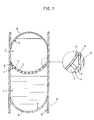
- La paroi selon la présente invention peut être plate. Cependant, dans le cas où l'on a un réservoir supérieur de volume important, il est avantageux que la cloison rigide ait une forme sensiblement hémisphérique. Dans ce cas, le voile est situé du côté convexe, c'est-à-dire en dessous de ladite cloison rigide. Une telle configuration est illustrée plus loin.
- Lorsque l'on souhaite des réservoirs de grand volume et/ou très résistants, ceux-ci sont avantageusement réalisés en métal. Ils sont alors de préférence réalisés en alliage métallique léger, de même que la cloison rigide de la paroi selon l'invention.
- Le voile peut être par exemple réalisé à partir d'un tissage métallique, de préférence du même métal que la cloison rigide, lorsque celle-ci est métallique.
- Ce tissage métallique est alors traité à l'aide d'un produit de manière avoir une certaine imperméabilité aux liquides, tout en conservant leur perméabilité aux gaz. La résistance du voile peut être calculée en fonction des contraintes qu'il devra subir.
- On peut également utiliser un tissu de verre par exemple enduit de PTFE. Des exemples de tels produits convenables pour le voile sont par exemple ceux commercialisé par la société Fothergill sous la référence TYGAVAC poreux.
- La présente invention sera mieux comprise si l'on se réfère aux dessins annexés, sur lesquels :
- - la figure 1 illustre une paroi selon la présente invention isolant l'un de l'autre deux réservoirs. On peut distinguer en 1 le réservoir inférieur contenant le liquide, en 2 le réservoir contenant le produit à l'état liquide ou solide. La cloison rigide 3 est séparée du voile 4 par des supports 5 ménageant ainsi un intervalle I susceptible de se remplir de gaz. On distingue également la cloison inférieure 6 du réservoir inférieur et la cloison supérieure 7 du réservoir supérieur qui peuvent être isolées par exemple par une mousse polyuréthanne 8 vis-à-vis de l'air extérieur. Les parois latérales 9 comprennent elles aussi un isolant 8.
- La perméabilité au gaz du voile peut être par exemple quantifiée par mesure de perte de charge ou mesure de vitesse de retour à un équilibre de pression après dépressurisation rapide.
- L'imperméabilité aux liquides est difficile à quantifier avec précision, uniquement par calcul : de nombreux paramètres doivent en effet être pris en compte (tolérance sur le tissage, mouillabilité, rétraction). Le choix du voile sera effectué de préférence au vu du résultat d'essais.
- Un tel essai peut être réalisé comme suit : on enfonce dans le liquide inférieur (par exemple de l'hydrogène liquide) un tube à l'origine ouvert aux deux extrémités, mais dont l'orifice inférieur est obturé par le voile à tester. En faisant varier par exemple la masse du tube d'essai, il est possible de quantifier avec précision une force d'imperméabilité.
- On prend un réservoir cryogénique H₂, O₂ liquides avec un fond commun. Le réservoir est en alliage d'aluminium.
- Une matière adaptée pour le voile est un tissu de verre enduit de PTFE. En effet, ce tissu possède un coefficient de rétraction très voisin de celui de l'alliage d'aluminium utilisé et sa porosité est facilement obtenue et contrôlée en fabrication industrielle, selon des méthodes connues en elles-mêmes.
- Le type de tissage et l'enduction en PTFE doivent prendre en compte :
- la vitesse de pressurisation et de dépressurisation du réservoir H₂ liquide ;
- l'imperméabilité au H₂ liquide. - La force d'imperméabilité nécessaire (en poids par unité de surface) doit être égale ou supérieure au poids par unité de surface du liquide placé au dessus du tissu. Dans la configuration explicitée par le croquis donné en annexe, le voile ne peut être mouillé que par des projections en cours de remplissage ou par le déplacement du liquide en vol en apesanteur, c'est-à-dire avec un poids nul. La force d'imperméabilité nécessaire devra donc uniquement être supérieure à zéro.
Claims (7)
1. Réservoir double avec un réservoir inférieur au-dessus duquel est superposé un réservoir supérieur, séparés entre eux par une paroi d'isolation thermique, caractérisé en ce que ladite paroi d'isolation thermique est une paroi double comportant une cloison rigide (3) supérieure et un voile inférieur (4), côté réservoir inférieur, qui est perméable aux gaz, mais étanche au liquide destiné à être contenu dans le réservoir inférieur, lesdits cloison rigide (3) et voile (4)étant maintenus écartés l'un de l'autre.
2. Réservoir double selon la revendication 1, caractérisé en ce que l'écartement de la cloison rigide (3) et du voile (4) est faible.
3. Réservoir double selon la revendication 1 ou 2, caractérisé en ce que l'écartement est maintenu à l'aide d'entretoises.
4. Réservoir double selon l'une quelconque des revendications 1 à 3, caractérisé en ce que l'écartement entre la cloison rigide (3) et le voile (4) est maintenu constant sur toute la surface de la paroi double.
5. Réservoir double selon l'une quelconque des revendications 1 à 4, caractérisé en ce que le voile (40) présente un coefficient de dilatation proche de celui de la cloison rigide (3).
6. Réservoir double selon l'une quelconque des revendications 1 à 5, caractérisé en ce que les supports sont fixés notamment par collage à la cloison (3) et/ou au voile (4).
7. Réservoir double selon l'une quelconque des revendications 1 à 6, caractérisé en ce que la cloison rigide (3) a une forme hémisphérique, le voile (4) étant situé du côté convexe.
Applications Claiming Priority (2)
| Application Number | Priority Date | Filing Date | Title |
|---|---|---|---|
| FR8911917 | 1989-09-12 | ||
| FR8911917A FR2651855B1 (fr) | 1989-09-12 | 1989-09-12 | Voile suspendu pour isolation thermique d'ergols cryogeniques. |
Publications (1)
| Publication Number | Publication Date |
|---|---|
| EP0418138A1 true EP0418138A1 (fr) | 1991-03-20 |
Family
ID=9385371
Family Applications (1)
| Application Number | Title | Priority Date | Filing Date |
|---|---|---|---|
| EP90402487A Withdrawn EP0418138A1 (fr) | 1989-09-12 | 1990-09-11 | Voile suspendu pour isolation thermique d'ergoles cryogéniques |
Country Status (3)
| Country | Link |
|---|---|
| US (1) | US5018634A (fr) |
| EP (1) | EP0418138A1 (fr) |
| FR (1) | FR2651855B1 (fr) |
Families Citing this family (25)
| Publication number | Priority date | Publication date | Assignee | Title |
|---|---|---|---|---|
| GB2264684B (en) * | 1992-03-03 | 1995-11-01 | Dowty Boulton Paul Ltd | Storage vessels |
| US5383566A (en) * | 1993-08-05 | 1995-01-24 | Edo Corporation, Fiber Science Division | Dual-chamber composite pressure vessel and method of fabrication thereof |
| FR2827940B1 (fr) * | 2001-07-27 | 2003-10-31 | Cryospace L Air Liquide Aerosp | Procede d'isolation thermique d'une structure metallique dont les deux faces sont soumises a des temperatures cryogeniques |
| FR2860059B1 (fr) * | 2003-09-18 | 2006-01-21 | Cryospace L Air Liquide Aerosp | Procede d'isolation thermique d'un double fond separant deux ergols d'un reservoir |
| US10125052B2 (en) | 2008-05-06 | 2018-11-13 | Massachusetts Institute Of Technology | Method of fabricating electrically conductive aerogels |
| US8785881B2 (en) | 2008-05-06 | 2014-07-22 | Massachusetts Institute Of Technology | Method and apparatus for a porous electrospray emitter |
| US10399709B2 (en) | 2008-07-18 | 2019-09-03 | The Boeing Company | Method of making a device for controlling stress in joints at cryogenic temperatures |
| US9453293B2 (en) | 2008-07-18 | 2016-09-27 | The Boeing Company | Method of making a composite tank having joint with softening strip |
| US8656571B2 (en) | 2008-07-18 | 2014-02-25 | The Boeing Company | Strong bonded joints for cryogenic applications |
| DE102008050404B4 (de) * | 2008-10-04 | 2010-07-22 | Mt Aerospace Ag | Behälter zum Aufnehmen und Speichern von Flüssigkeiten und viskosen Stoffen, insbesondere von kryogenen Fluiden, und Verfahren zu dessen Herstellung sowie zur Verwendung dessen |
| DE102010035911A1 (de) * | 2010-05-31 | 2011-12-01 | Mt Aerospace Ag | Behälter zum Aufnehmen und Speichern von Flüssigkeiten und viskosen Stoffen, insbesondere von kryogenen Fluiden, und Verfahren zu dessen Herstellung sowie dessen Verwendung |
| US8974135B2 (en) | 2010-07-22 | 2015-03-10 | The Boeing Company | Fabric preform insert for a composite tank Y-joint |
| US8939407B2 (en) * | 2011-02-15 | 2015-01-27 | The Boeing Company | Common bulkhead for composite propellant tanks |
| US10308377B2 (en) | 2011-05-03 | 2019-06-04 | Massachusetts Institute Of Technology | Propellant tank and loading for electrospray thruster |
| FR2977239B1 (fr) | 2011-07-01 | 2015-10-23 | Air Liquide | Reservoir de fluide cryogenique et son utilisation |
| CN104747899A (zh) * | 2013-12-25 | 2015-07-01 | 柳州市京阳节能科技研发有限公司 | 高效节能环保沼气积存罐 |
| DE102015002708B3 (de) | 2014-09-09 | 2015-10-22 | Mt Aerospace Ag | Behälter zum Aufnehmen und Speichern von Flüssigkeiten und viskosen Stoffen, insbesondere von kryogenen Fluiden, und Verfahren zu dessen Herstellung sowie dessen Verwendung |
| WO2016164004A1 (fr) * | 2015-04-08 | 2016-10-13 | Massachusetts Institute Of Technology | Réservoir de propergol et chargement pour propulseur par électronébulisation |
| US9597859B2 (en) * | 2015-05-27 | 2017-03-21 | The Boeing Company | Self-sealing bladders and related methods |
| US10065751B2 (en) * | 2016-04-05 | 2018-09-04 | Orbital Atk, Inc. | Liquid storage tanks and systems and propulsion systems for space vehicles and related methods |
| US10141855B2 (en) | 2017-04-12 | 2018-11-27 | Accion Systems, Inc. | System and method for power conversion |
| EP3973182A4 (fr) | 2019-05-21 | 2023-06-28 | Accion Systems, Inc. | Appareil d'émission par électronébulisation |
| DE102019118323B4 (de) * | 2019-07-05 | 2021-06-10 | Arianegroup Gmbh | Tank sowie Verfahren |
| US12104583B2 (en) | 2020-08-24 | 2024-10-01 | Accion Systems, Inc. | Propellant apparatus |
| US12049855B1 (en) * | 2023-05-27 | 2024-07-30 | Victoria Arel Lucas | Method and apparatus for reducing consequences of a bulkhead failure for a liquid methane and liquid oxygen rocket |
Citations (3)
| Publication number | Priority date | Publication date | Assignee | Title |
|---|---|---|---|---|
| FR2096139A5 (fr) * | 1970-06-09 | 1972-02-11 | Martin Marietta Corp | |
| FR2111455A5 (fr) * | 1970-10-16 | 1972-06-02 | Martin Marietta Corp | |
| US3756024A (en) * | 1962-02-23 | 1973-09-04 | Gen Dynamics Corp | Method and apparatus for coordinating propulsion in a single stage space flight |
Family Cites Families (6)
| Publication number | Priority date | Publication date | Assignee | Title |
|---|---|---|---|---|
| US2995268A (en) * | 1958-09-05 | 1961-08-08 | Boeing Co | Insulated tank construction |
| NL258995A (fr) * | 1960-01-11 | |||
| US3215313A (en) * | 1964-10-01 | 1965-11-02 | Air Prod & Chem | Low heat leak connector for cryogenic system |
| BE757662A (fr) * | 1969-10-18 | 1971-04-01 | Kvaerner Brug As | Dispositif pour monter des reservoirs separes a bord d'un navire |
| US3765558A (en) * | 1971-01-04 | 1973-10-16 | Arctic Tanker Group Inc | Cryogenic tank design and method of manufacture |
| US3713560A (en) * | 1971-04-19 | 1973-01-30 | Gen Dynamics Corp | Spaced wall container |
-
1989
- 1989-09-12 FR FR8911917A patent/FR2651855B1/fr not_active Expired - Fee Related
-
1990
- 1990-09-11 EP EP90402487A patent/EP0418138A1/fr not_active Withdrawn
- 1990-09-12 US US07/581,614 patent/US5018634A/en not_active Expired - Fee Related
Patent Citations (3)
| Publication number | Priority date | Publication date | Assignee | Title |
|---|---|---|---|---|
| US3756024A (en) * | 1962-02-23 | 1973-09-04 | Gen Dynamics Corp | Method and apparatus for coordinating propulsion in a single stage space flight |
| FR2096139A5 (fr) * | 1970-06-09 | 1972-02-11 | Martin Marietta Corp | |
| FR2111455A5 (fr) * | 1970-10-16 | 1972-06-02 | Martin Marietta Corp |
Also Published As
| Publication number | Publication date |
|---|---|
| FR2651855B1 (fr) | 1991-12-27 |
| US5018634A (en) | 1991-05-28 |
| FR2651855A1 (fr) | 1991-03-15 |
Similar Documents
| Publication | Publication Date | Title |
|---|---|---|
| FR2651855A1 (fr) | Voile suspendu pour isolation thermique d'ergols cryogeniques. | |
| EP0170025B1 (fr) | Dispositif d'assemblage d'élément filtrant tubulaire dans une enveloppe | |
| CA2145235C (fr) | Conteneur a double paroi pour le transport et le stockage d'un gaz liquifie | |
| EP0070760B1 (fr) | Procédé de traitement d'une masse liquide sans contact avec les parois d'un dispositif et application de ce procédé à la mise en forme de matériaux en microgravite | |
| US5458719A (en) | Method for bonding a porous medium to a substrate | |
| EP1825185B1 (fr) | Procédé d'isolation thermique de conduites coaxiales par un matériau isolant particulaire, installation pour la mise en ouvre du dit procédé, élément de conduites coaxiales et conduite | |
| BE1018534A3 (fr) | Procede pour la separation avec purification de cristaux acrylique, d'acide methacrylique, de n-vinulpyrrolidone ou de p-xylene a partir de leur suspension dans une lessive-mere. | |
| FR2804188A1 (fr) | Amortisseur a haut pouvoir dissipatif | |
| EP0132175B2 (fr) | Réservoir de stockage de liquide à confinement capillaire | |
| EP2283272B1 (fr) | Fixation par collage de blocs isolants pour cuve de stockage de gaz liquefies a l'aide de cordons ondules | |
| EP0154295B1 (fr) | Dispositif de séparation par membrane, et procédés de fabrication de celui-ci | |
| Agrawal et al. | High flux freeze‐dried cellulose acetate reverse osmosis membranes as microporous barriers in gas permeation and separation | |
| Germic et al. | Characterization of polyacrylonitrile ultrafiltration membranes | |
| FR2918399A1 (fr) | Coffrage a elements internes filtrants pour realiser un voile en beton de grande epaisseur | |
| GB2361285A (en) | Cryogenic fluid transfer tube | |
| US10883911B2 (en) | Method and arrangement for determining at least one pore-related parameter of a porous structure | |
| EP1279885A1 (fr) | Procédé d'isolation thermique d'une structure metallique dont les deux faces sont soumises à des températures cryogéniques | |
| EP0569498A1 (fr) | Element de garnissage interieur pour manchons | |
| WO1992014538A1 (fr) | Procede de fabrication d'une plaque de gel d'electrophorese | |
| EP0043774A1 (fr) | Procédé et dispositif pour la coalescence d'une phase finement dispersée d'un mélange fluide | |
| WO2006136694A1 (fr) | Moyen d'inertage a faible vitesse et dispositif mettant en œuvre ce moyen d'inertage pour conditionner un produit alimentaire | |
| Gajdošíková et al. | Surface phenomena and wetting of porous solids | |
| FR2498866A1 (fr) | Carter de maintien pour transducteur electroacoustique de puissance soumis a de fortes pressions hydrostatiques | |
| WO1998033599A1 (fr) | Systeme d'alimentation en liquide pour appareil dans lequel est maintenu un niveau constant | |
| FR2953928A1 (fr) | Methode de mesure de l'adherence de la glace sur une surface |
Legal Events
| Date | Code | Title | Description |
|---|---|---|---|
| PUAI | Public reference made under article 153(3) epc to a published international application that has entered the european phase |
Free format text: ORIGINAL CODE: 0009012 |
|
| AK | Designated contracting states |
Kind code of ref document: A1 Designated state(s): DE ES GB IT NL |
|
| 17P | Request for examination filed |
Effective date: 19910418 |
|
| RAP1 | Party data changed (applicant data changed or rights of an application transferred) |
Owner name: CRYOSPACE |
|
| 17Q | First examination report despatched |
Effective date: 19920909 |
|
| STAA | Information on the status of an ep patent application or granted ep patent |
Free format text: STATUS: THE APPLICATION IS DEEMED TO BE WITHDRAWN |
|
| 18D | Application deemed to be withdrawn |
Effective date: 19931030 |