EP0418202A2 - Capteur optique à interférométrie intermodale - Google Patents
Capteur optique à interférométrie intermodale Download PDFInfo
- Publication number
- EP0418202A2 EP0418202A2 EP90810697A EP90810697A EP0418202A2 EP 0418202 A2 EP0418202 A2 EP 0418202A2 EP 90810697 A EP90810697 A EP 90810697A EP 90810697 A EP90810697 A EP 90810697A EP 0418202 A2 EP0418202 A2 EP 0418202A2
- Authority
- EP
- European Patent Office
- Prior art keywords
- mode
- optical fiber
- intermodal
- optical
- bimodal
- Prior art date
- Legal status (The legal status is an assumption and is not a legal conclusion. Google has not performed a legal analysis and makes no representation as to the accuracy of the status listed.)
- Granted
Links
Images
Classifications
-
- G—PHYSICS
- G01—MEASURING; TESTING
- G01L—MEASURING FORCE, STRESS, TORQUE, WORK, MECHANICAL POWER, MECHANICAL EFFICIENCY, OR FLUID PRESSURE
- G01L1/00—Measuring force or stress, in general
- G01L1/24—Measuring force or stress, in general by measuring variations of optical properties of material when it is stressed, e.g. by photoelastic stress analysis using infrared, visible light, ultraviolet
- G01L1/242—Measuring force or stress, in general by measuring variations of optical properties of material when it is stressed, e.g. by photoelastic stress analysis using infrared, visible light, ultraviolet the material being an optical fibre
- G01L1/243—Measuring force or stress, in general by measuring variations of optical properties of material when it is stressed, e.g. by photoelastic stress analysis using infrared, visible light, ultraviolet the material being an optical fibre using means for applying force perpendicular to the fibre axis
- G01L1/245—Measuring force or stress, in general by measuring variations of optical properties of material when it is stressed, e.g. by photoelastic stress analysis using infrared, visible light, ultraviolet the material being an optical fibre using means for applying force perpendicular to the fibre axis using microbending
-
- G—PHYSICS
- G01—MEASURING; TESTING
- G01D—MEASURING NOT SPECIALLY ADAPTED FOR A SPECIFIC VARIABLE; ARRANGEMENTS FOR MEASURING TWO OR MORE VARIABLES NOT COVERED IN A SINGLE OTHER SUBCLASS; TARIFF METERING APPARATUS; MEASURING OR TESTING NOT OTHERWISE PROVIDED FOR
- G01D5/00—Mechanical means for transferring the output of a sensing member; Means for converting the output of a sensing member to another variable where the form or nature of the sensing member does not constrain the means for converting; Transducers not specially adapted for a specific variable
- G01D5/26—Mechanical means for transferring the output of a sensing member; Means for converting the output of a sensing member to another variable where the form or nature of the sensing member does not constrain the means for converting; Transducers not specially adapted for a specific variable characterised by optical transfer means, i.e. using infrared, visible, or ultraviolet light
- G01D5/266—Mechanical means for transferring the output of a sensing member; Means for converting the output of a sensing member to another variable where the form or nature of the sensing member does not constrain the means for converting; Transducers not specially adapted for a specific variable characterised by optical transfer means, i.e. using infrared, visible, or ultraviolet light by interferometric means
-
- G—PHYSICS
- G01—MEASURING; TESTING
- G01D—MEASURING NOT SPECIALLY ADAPTED FOR A SPECIFIC VARIABLE; ARRANGEMENTS FOR MEASURING TWO OR MORE VARIABLES NOT COVERED IN A SINGLE OTHER SUBCLASS; TARIFF METERING APPARATUS; MEASURING OR TESTING NOT OTHERWISE PROVIDED FOR
- G01D5/00—Mechanical means for transferring the output of a sensing member; Means for converting the output of a sensing member to another variable where the form or nature of the sensing member does not constrain the means for converting; Transducers not specially adapted for a specific variable
- G01D5/26—Mechanical means for transferring the output of a sensing member; Means for converting the output of a sensing member to another variable where the form or nature of the sensing member does not constrain the means for converting; Transducers not specially adapted for a specific variable characterised by optical transfer means, i.e. using infrared, visible, or ultraviolet light
- G01D5/268—Mechanical means for transferring the output of a sensing member; Means for converting the output of a sensing member to another variable where the form or nature of the sensing member does not constrain the means for converting; Transducers not specially adapted for a specific variable characterised by optical transfer means, i.e. using infrared, visible, or ultraviolet light using optical fibres
Definitions
- the present invention relates, in general, to distributed sensors with mode coupling generated by a disturbance whose position we want to determine along a light guide and relates more particularly to an optical sensor with intermodal interferometry.
- the document "Birefringent stress location sensor” (RB Franks et al., SPIE, vol. 586, Fiber Optic Sensors 1985) shows a distributed sensor using a laser source, frequency modulated, injecting a single mode into a birefringent or single mode optical fiber used as a bimodal fiber. Under the effect of an external parameter, a disturbance - in this case micro-bends - generates a coupling of modes giving rise to the propagation of a second mode in the fiber. Detection is carried out by intermodal interferometry. The determination of the position of the disturbance is deduced from the measurement of the beat frequency of the detection signal.
- the problems posed by this solution are multiple.
- the measurement of the coupling rate and the determination of the position of said coupling along the fiber are made difficult by problems: - linearity of the frequency ramp of the modulation signal, - source stability, - backscattering and - attenuation of detection due to polarization and mixing of modes.
- an object of the invention is an optical sensor for determining the position of a disturbance along an optical fiber, not having the drawbacks mentioned above and providing a solution to the problems mentioned above.
- Another object is an optical sensor, the determination of the position of the disturbance is made by inter-modal interferometry.
- the main advantages of this invention reside in the fact that the system dynamics and the spatial resolution are increased compared to those of known solutions. As the sensor works in transmission, almost all of the energy injected is detected. The electronics remain the same whether the system has one or more transducers.
- the light source in particular with regard to its polarization and its stability, does not require the most stringent characteristics. Unlike an optical system by optical reflectometry in the time domain (OTDR) or frequency (OFDR), the sensor of the invention does not require averaging over a large number of measurements and therefore the system response time is longer short.
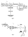
- Fig. 1 is a block diagram of the optical fiber sensor according to the invention.
- the optical sensor with intermodal interferometry 1 mainly comprises, following the optical path, a light source 2, a bimodal optical fiber 4 along which are distributed transducers 5, an interferometer 6, a first 8 and a second 9 systems detection devices connected to a measure 10.
- a mode filter 3 can be used at the input of said optical fiber.
- the first end of the optical fiber is then connected to said mode filter 3.
- the light source and optical fiber link would constitute a first transducer. In all cases, the second end faces said interferometer.
- the optical sensor with intermodal interferometry uses a light source 2 emitting a non-monochromatic light wave.
- the modes other than the fundamental LP01 mode or the polarization mode are filtered at the input of the optical fiber 4 by the mode filter 3.
- Optical fiber 4 which is single-mode in a given wavelength range, for example around 1.3 ⁇ m, in fact propagates waves of shorter wavelength, for example 0.8 ⁇ m.
- the optical fiber 4 can be subjected, via the transducers 5 to one or more disturbances, localized or distributed, generated by the physical or chemical quantity to be detected. Under the effect of such a disturbance, the injected mode propagating in the optical fiber 4 can be coupled to a higher order mode. The two modes then propagate in the guide with a coupling rate depending on the amplitude of the disturbance and at different propagation speeds.
- the delay time between these modes is proportional to the difference between the optical paths traveled, in the bimodal optical fiber, by each of the modes. It is the difference between the propagation speeds of the two modes which cause a difference between the optical paths. The determination of this difference between optical paths makes it possible to deduce the position of the disturbance which gave rise to the coupled mode.
- This determination is made by injecting the light wave leaving the optical fiber into the interferometer.
- the measurement relates, firstly, to the interference product delivered at the output of the interferometer.
- Interference between the light waves propagating in each of the two branches of the interferometer is obtained in two cases: . when the two optical paths of the interferometer are equal, this independently of the disturbances along the optical fiber and . when the difference in optical path between the two branches of the interferometer compensates for the difference between the optical paths traveled in the fiber by each of the modes.
- each mode interferes with itself.
- the introduction of a difference in optical path between the two branches of the interferometer is obtained by a modification of the length and / or of the refractive index of at least one of the branches of the interferometer.
- the modification of the length of a branch of the interferometer is obtained, for example in the case of a Michelson type interferometer, by moving the mobile mirror (reference 7 in FIG. 2) of said interferometer.
- each transducer distributed along the optical fiber is associated, unequivocally, with a given variation. It follows from the above that the measurement also relates to said variation.
- the first and second detection systems detect, respectively, the maximum of the interference product and the corresponding variation.
- the measurement unit deduces from these measurements the position of the disturbance along the optical fiber.
- the difference between the propagation times of the modes is of the order of 2 picoseconds, for a source consisting of a light-emitting diode with a wavelength of 880 nm.
- the precision obtained in determining the position of the disturbance is a function of the precision with which the first detection system can locate the maximum of the amplitude of the interference fringes.
- a resolution of less than 50 ⁇ m could be obtained, ie a temporal resolution of less than 0.2 picoseconds. This time interval corresponds to a propagation in the bimodal fiber of 5 mm.
- the spatial resolution of the optical sensor with intermodal interferometry is less than 5 mm.
- the total number of transducers that can be multiplexed depends on the width of the intermodal interference phenomenon. Said width is equal to the coherence length of the light source. In other words, the total number of transducers that can be multiplexed is given by the ratio of the range of displacement of the movable mirror to the coherence length of the source.
- the number of transducers is close to 55.
- Fig. 2 represents a first embodiment example according to which the light source 2 is a multimode laser diode.
- the modes other than the fundamental guided mode LP01 are filtered at the input of the optical fiber 4 by a mode filter 3.
- This is constituted by a laterally polished fiber in which only the fundamental mode, the modes of higher order being written off to the outside.
- the index n1 of the external medium surrounding said polished fiber must satisfy the relation: n11 ⁇ n1 ⁇ n01, n01 and n11 representing, respectively, the effective indices of the fundamental mode LP01 and of the order mode a LP11.
- Optical fiber 4 single mode in a given range of wavelengths, typically around 1.3 ⁇ m, which propagates the fundamental mode of lower wavelength, typically 0.8 ⁇ m, is subjected to disturbances transmitted by transducers 5 distributed along said fiber.
- the transducers can be simultaneously active.
- the optical sensor with intermodal interferometry generally consists of a light source 2 coupled to a mode filter 3 which can be: a polished fiber as described by RA BERGH et al., "Single-mode fiber-optic polarizer, "Optics Letters / Vol. 5, No. 11 / November 1980, pp. 479-481, two fibers - one bimodal, the other monomode - connected end to end or a fiber bevelled by stretching under high temperature (cf. V. SHAH et al. / "Biconical tapered fiber-mode filter for bimodal systems "/ OFC 88 / WQ 13).
- the optical fiber 4 is a single-mode fiber at a given wavelength and operating at a lower wavelength, the modes liable to propagate being guided modes: fundamental mode LP01, order mode a LP11 and possibly modes d 'higher order.
- the optical fiber 4 can also be a birefringent fiber propagating polarization modes.
- the transducers arranged along the optical fiber are all devices, such as microbending transducers, making it possible to generate a coupling between modes under the action of the parameter to be detected.
- a single mode or bimodal optical fiber facing a bimodal optical fiber can be used as a mode coupled transducer.
- the interferometer is of the Michelson type, of the Mach-Zehnder type or even of the Fabry-Perot type.
- the light source is a non-monochromatic photodiode, for example a KFD-1060 photodiode from the company EG. & G. Photon Devices.
- This photodiode is associated with external electronic components which determine the bandwidth of 80 kHz necessary for the detection of the interference product. Due to the symmetry of the LP modes which are to interfere, the detection must relate only to the negative or positive part of the interference product, so that these two parts do not compensate each other.
- the optical sensor of the invention is used to detect and determine the position of a variation of an environment parameter and is used, for example, as an intrusion, force, pressure or temperature detector, or else as a hydrogen sensor
Landscapes
- Physics & Mathematics (AREA)
- General Physics & Mathematics (AREA)
- Instruments For Measurement Of Length By Optical Means (AREA)
- Length Measuring Devices By Optical Means (AREA)
- Investigating Or Analysing Materials By Optical Means (AREA)
- Optical Transform (AREA)
- Photometry And Measurement Of Optical Pulse Characteristics (AREA)
- Radiation Pyrometers (AREA)
- Glass Compositions (AREA)
Abstract
Description
- La présente invention se rapporte, de manière générale, aux capteurs distribués à couplage de modes engendré par une perturbation dont on veut déterminer la position le long d'un guide de lumière et concerne plus particulièrement un capteur optique à interférométrie intermodale.
- Le document "Birefringent stress location sensor" (R.B. Franks et al., SPIE, vol. 586, Fiber Optic Sensors 1985) montre un capteur distribué utilisant une source laser, modulée en fréquence, injectant un seul mode dans une fibre optique biréfringente ou monomode utilisée comme une fibre bimodale. Sous l'effet d'un paramètre extérieur, une perturbation - en l'occurence des microcourbures - engendre un couplage de modes donnant naissance à la propagation d'un deuxième mode dans la fibre. La détection est réalisée par interférométrie intermodale. La détermination de la position de la perturbation est déduite de la mesure de la fréquence de battement du signal de détection.
- Les problèmes posés par cette solution sont multiples. La mesure du taux de couplage et la détermination de la position dudit couplage le long de la fibre, sont rendues difficiles par des problèmes :
- de linéarité de la rampe de fréquence du signal de modulation,
- de stabilité de la source,
- de rétrodiffusion et
- d'atténuation de la détection due à la polarisation et au mélange des modes. - Aussi un objet de l'invention est-il un capteur optique permettant la détermination de la position d'une perturbation le long d'une fibre optique, ne présentant pas les inconvénients mentionnés ci-dessus et apportant une solution aux problèmes évoqués précédemment.
- Un autre objet est un capteur optique dont la détermination de la position de la perturbation se fait par interférométrie inter-modale.
- Les caractéristiques de l'invention sont définies dans les revendications.
- Les avantages principaux de cette invention résident dans le fait que la dynamique du système et la résolution spatiale sont augmentées par rapport à celles des solutions connues. Comme le capteur travaille en transmission, presque toute l'énergie injectée est détectée. L'électronique reste identique, que le système comporte un seul ou plusieurs transducteurs. La source de lumière, notamment en ce qui concerne sa polarisation et sa stabilité, ne nécessite pas des caractéristiques des plus strictes. Contrairement à un système optique par réflectométrie optique dans le domaine temporel (OTDR) ou fréquentiel (OFDR), le capteur de l'invention ne nécessite pas de moyennage sur un grand nombre de mesures et de ce fait le temps de réponse du système est plus court.
- D'autres objets, caractéristiques et avantages de la présente invention apparaîtront plus clairement à la lecture de la description suivante faite en relation avec les dessins joints dans lesquels :
- la fig. 1 est une représentation synoptique du capteur optique à interférométrie intermodale de l'invention et
- la fig. 2 est un exemple de réalisation du capteur optique.
- La fig. 1 est une représentation synoptique du capteur à fibre optique selon l'invention.
- Le capteur optique à interférométrie intermodale 1 comporte, principalement, en suivant le trajet optique, une source de lumière 2, une fibre optique bimodale 4 le long de laquelle sont répartis des transducteurs 5, un interféromètre 6, un premier 8 et un deuxième 9 systèmes de détection connectés à une unité de mesure 10.
- Un filtre de modes 3 peut être utilisé à l'entrée de ladite fibre optique. La première extrémité de la fibre optique est alors connectée audit filtre de modes 3. En l'absence de filtre de modes à l'entrée de ladite fibre optique, la liaison source de lumière et fibre optique constituerait un premier transducteur. Dans tous les cas, la deuxième extrémité fait face audit interféromètre.
- Le capteur optique à interférométrie intermodale utilise une source de lumière 2 émettant une onde de lumière non monochromatique.
- Le filtrage des modes autres que le mode fondamental LP₀₁ ou le mode de polarisation est effectué à l'entrée de la fibre optique 4 par le filtre de modes 3.
- La fibre optique 4, qui est monomode dans une gamme donnée de longueur d'ondes, par exemple autour de 1,3 µm, propage en fait des ondes de plus faible longueur d'onde, par exemple 0,8 µm.
- La fibre optique 4 peut être soumise, par l'intermédiaire des transducteurs 5 à une ou plusieurs perturbations, localisées ou distribuées, engendrées par la grandeur physique ou chimique à détecter. Sous l'effet d'une telle perturbation, le mode injecté se propageant dans la fibre optique 4 peut être couplé à un mode d'ordre supérieur. Les deux modes se propagent alors dans le guide avec un taux de couplage dépendant de l'amplitude de la perturba-tion et à des vitesses de propagation différentes.
- A l'entrée de l'interféromètre on observe une différence de temps d'arrivée entre le mode injecté et le mode couplé. Le temps de retard entre ces modes est proportionnel à la différence entre les chemins optiques parcourus, dans la fibre optique bimodale, par chacun des modes. C'est la différence entre les vitesses de propagation des deux modes qui entraînent une différence entre les chemins optiques. La détermination de cette différence entre chemins optiques permet de déduire la position de la perturbation ayant donné naissance au mode couplé.
- Cette détermination est faite en injectant l'onde lumineuse sortant de la fibre optique dans l'interféromètre. La mesure porte, dans un premier temps, sur le produit d'interférence délivré en sortie de l'interféromètre.
- Des interférences entre les ondes lumineuses se propageant dans chacune des deux branches de l'interféromètre sont obtenues dans deux cas :
. lorsque les deux chemins optiques de l'interféromètre sont égaux, ceci indépendemment des perturbations le long de la fibre optique et
. lorsque la différence de chemin optique entre les deux branches de l'interféromètre compense la différence entre les chemins optiques parcourus dans la fibre par chacun des modes. - Dans le premier cas chaque mode interfère avec lui-même.
- L'introduction d'une différence de chemin optique entre les deux branches de l'interféromètre est obtenue par une modification de la longueur et/ou de l'indice de réfraction d'au moins une des branches de l'interféromètre. La modification de la longueur d'une branche de l'interféromètre est obtenue, par exemple dans le cas d'un interféromètre du type Michelson, en déplaçant le miroir mobile (référence 7 dans la fig. 2) dudit interféromètre. Chacune des variations apportées permet la compensation du temps de retard entre modes à l'entrée de l'interféromètre, temps de retard défini par chacun des transducteurs répartis le long de la fibre.
- En d'autres termes, chaque transducteur réparti le long de la fibre optique est associé, de manière biunivoque, à une variation donnée. Il découle de ce qui précède que la mesure porte également sur ladite variation.
- Les premier et deuxième systèmes de détection détectent, respectivement, le maximum du produit d'interférence et la variation correspondante. L'unité de mesure déduit de ces mesures la position de la perturbation le long de la fibre optique.
- A titre d'exemple, pour une longueur de fibre de un mètre la différence entre les temps de propagation des modes est de l'ordre de 2 picosecondes, pour une source constituée d'une diode électroluminescente de longeur d'onde de 880 nm.
- La précision obtenue sur la détermination de la position de la perturbation est fonction de la précision avec laquelle le premier système de détection peut localiser le maximum de l'amplitude des franges d'interférence. Une résolution inférieure à 50 µm a pu être obtenue, soit une résolution temporelle inférieure à 0.2 picoseconde. Cet intervalle temporel correspond à une propagation dans la fibre bimodale de 5 mm. En d'autres termes, la résolution spatiale du capteur optique à interférométrie intermodale est inférieure à 5 mm.
- Le nombre total des transducteurs que l'on peut multiplexer, par exemple dans la plage de déplacement du miroir mobile d'un interféromètre de type Michelson, dépend de la largeur du phénomène d'interférence intermodale. Ladite largeur est égale à la longueur de cohérence de la source de lumière. En d'autres termes, le nombre total de transducteurs pouvant être multiplexé est donné par le rapport plage de déplacement du miroir mobile sur longueur de cohérence de la source.
- A titre d'exemple : pour une source de largeur spectrale à mi-hauteur de 70 nm et de longueur de cohérence de 700 µm et pour un interféromètre autorisant une plage de déplacement du miroir mobile de 40 mm, le nombre de transducteurs est voisin de 55.
- La fig. 2 représente un premier exemple de réalisation selon lequel la source lumineuse 2 est une diode laser multimode. Les modes autres que le mode guidé fondamental LP₀₁ sont filtrés à l'entrée de la fibre optique 4 par un filtre de modes 3. Celui-ci est constitué par une fibre polie latéralement dans laquelle seul reste guidé le mode fondamental, les modes d'ordre supérieur étant radiés vers l'extérieur. Pour cela l'indice n₁ du milieu extérieur entourant ladite fibre polie doit satisfaire la relation : n₁₁<n₁<n₀₁, n₀₁ et n₁₁ représentant, respectivement, les indices effectifs du mode fondamental LP₀₁ et du mode d'ordre un LP₁₁. La fibre optique 4, monomode dans une gamme donnée de longueurs d'ondes, typiquement autour de 1,3 µm, qui propage le mode fondamental de longueur d'onde plus faible, typiquement 0,8 µm, est soumise à des perturbations transmises par des transducteurs 5 distribués le long de ladite fibre. Les transducteurs peuvent être simultanément actifs. Lesdits transducteurs 5 engendrent des microcourbures de la fibre de période spatiale Λ, déterminée de façon à ce que l'expression Λ = λ₀ (ne01 - ne011),
où λ₀ est la longueur d'onde centrale de la source
ne01 l'indice effectif du mode fondamental LP₀₁
ne11 l'indice effectif du mode d'onde un LP₁₁,
soit vérifiée. - Le capteur optique à interférométrie intermodale se compose de manière générale d'une source de lumière 2 couplée à un filtre de modes 3 pouvant être : une fibre polie telle que décrite par R.A. BERGH et al., "Single-mode fiber-optic polarizer," Optics Letters/ Vol. 5, No. 11/ November 1980, pp. 479-481, deux fibres - l'une bimodale, l'autre monomode - connectées bout à bout ou encore une fibre biseautée par étirage sous haute température (cf. V. SHAH et al. / "Biconical tapered fiber-mode filter for bimodal systems" / OFC 88 / WQ 13).
- La fibre optique 4 est une fibre monomode à une longueur d'onde donnée et fonctionnant à une longueur d'onde inférieure, les modes susceptibles de se propager étant des modes guidés : mode fondamental LP₀₁, mode d'ordre un LP₁₁ et éventuellement modes d'ordre supérieur.
- La fibre optique 4 peut encore être une fibre biréfringente propageant des modes de polarisation.
- Les transducteurs disposés le long de la fibre optique sont tous dispositifs, tels les transducteurs à microcourbures, permettant d'engendrer un couplage entre modes sous l'action du paramètre à détecter. Une fibre optique monomode ou bimodale faisant face à une fibre optique bimodale peut être utilisée comme transducteur à couplage de modes.
- L'interféromètre est du type Michelson, du type Mach-Zehnder ou encore du type Fabry-Perot.
- La source de lumière est une photodiode non monochromatique, par exemple une photodiode KFD-1060 de la société EG. & G. Photon Devices. Cette photodiode est associée à des composants électroniques externes qui déterminent la bande passante de 80 KHz nécessaire a la détection du produit d'interférence. Du fait de la symétrie des modes LP devant interférer, la détection ne doit porter que sur la partie négative ou positive du produit d'interférence, afin que ces deux parties ne se compensent pas.
- Le capteur optique de l'invention est utilisé pour détecter et déterminer la position d'une variation d'un paramètre d'environnement et est utilisé, par exemple, comme détecteur d'intrusion, de force, de pression ou de température, ou encore comme capteur d'hydrogène
- Bien que la présente invention ait été décrite dans le cadre d'un exemple de réalisation particulier, il est clair, cependant, qu'elle est susceptible de modification ou de variantes sans sortir de son domaine.
Claims (7)
- des moyens optiques permettant respectivement
. l'émission d'une onde lumineuse;
. l'injection dans une fibre optique bimodale (4) de ladite onde lumineuse;
. le guidage de ladite onde lumineuse au moyen d'une fibre optique bimodale;
- des moyens répartis le long de ladite fibre optique bimodale permettant le couplage du mode fondamental LP₀₁ ou du mode de polarisation de ladite onde lumineuse injecté au mode d'ordre un LP₁₁ ou au mode de polarisation orthogonale, respectivement;
- un interféromètre (6) permettant la compensation de la différence du temps de retard entre modes couplés à l'entrée de l'interféromètre, par modification des conditions d'inter-férence dudit interféromètre;
- des moyens électriques permettant
. la mesure de ladite modification apportée audit interféromètre;
. la détection, en intensité, dudit produit d'interférence;
. la détermination de la position, le long de ladite fibre optique bimodale, de la perturbation ayant créé le couplage intermodal.
soit d'une fibre bimodale connectée à une fibre monomode,
soit d'une fibre bimodale polie ou
soit d'une fibre biseautée par étirage sous haute température,
guides d'ondes dans lesquels ne subsiste que le mode guidé fondamental LP₀₁ ou le mode de polarisation, les autres modes étant purgés.
soit d'une fibre optique monomode pour une gamme donnée de longueurs d'ondes et fonctionnant dans une gamme de longueurs d'ondes plus basses permettant la propagation de modes guidés non couplés ou
soit d'une fibre optique biréfringente permettant la propagation de modes de polarisation.
soit d'un interféromètre de type Michelson,
soit d'un interféromètre de type Mach-Zehnder,
soit d'un interféromètre de type Fabry-Perot.
- soit des transducteurs engendrant des microcourbures de périodes spatiales données,
- soit une fibre optique monomode faisant face à une fibre optique bimodale,
- soit une fibre optique bimodale faisant face à une fibre optique bimodale.
Applications Claiming Priority (2)
| Application Number | Priority Date | Filing Date | Title |
|---|---|---|---|
| CH3374/89A CH681570A5 (fr) | 1989-09-15 | 1989-09-15 | |
| CH3374/89 | 1989-09-15 |
Publications (3)
| Publication Number | Publication Date |
|---|---|
| EP0418202A2 true EP0418202A2 (fr) | 1991-03-20 |
| EP0418202A3 EP0418202A3 (en) | 1991-10-16 |
| EP0418202B1 EP0418202B1 (fr) | 1995-02-08 |
Family
ID=4254578
Family Applications (1)
| Application Number | Title | Priority Date | Filing Date |
|---|---|---|---|
| EP19900810697 Expired - Lifetime EP0418202B1 (fr) | 1989-09-15 | 1990-09-14 | Capteur optique à interférométrie intermodale |
Country Status (6)
| Country | Link |
|---|---|
| US (1) | US5067815A (fr) |
| EP (1) | EP0418202B1 (fr) |
| JP (1) | JP2996704B2 (fr) |
| AT (1) | ATE118274T1 (fr) |
| CH (1) | CH681570A5 (fr) |
| DE (1) | DE69016720T2 (fr) |
Families Citing this family (10)
| Publication number | Priority date | Publication date | Assignee | Title |
|---|---|---|---|---|
| DE69206654T2 (de) * | 1991-03-26 | 1996-07-11 | Hamamatsu Photonics Kk | Optischer Spannungsdetektor |
| JPH06307953A (ja) * | 1993-04-27 | 1994-11-04 | Hitachi Ltd | 物理量検出装置 |
| US5831263A (en) * | 1994-04-26 | 1998-11-03 | Hitachi, Ltd. | In-cylinder pressure sensing apparatus for multi-cylinder engine |
| US7473906B2 (en) | 2005-04-28 | 2009-01-06 | Claudio Oliveira Egalon | Reversible, low cost, distributed optical fiber sensor with high spatial resolution |
| FR2906887B1 (fr) * | 2006-10-10 | 2008-12-12 | Genesis France | Dispositif de transport d'une substance muni d'un detecteur optique de fuite |
| US8463083B2 (en) * | 2009-01-30 | 2013-06-11 | Claudio Oliveira Egalon | Side illuminated multi point multi parameter optical fiber sensor |
| WO2015163963A2 (fr) | 2014-02-10 | 2015-10-29 | University Of Central Florida Research Foundation, Inc. | Appareil à fibres optiques multicœurs, procédés et applications |
| WO2016053398A1 (fr) * | 2014-09-30 | 2016-04-07 | Darma Inc. | Systèmes et procédés de surveillance de signes vitaux et de posture |
| EP3677874A1 (fr) * | 2019-01-02 | 2020-07-08 | Nokia Technologies Oy | Détection de non-uniformités dans une fibre optique |
| CN113959606B (zh) * | 2021-10-20 | 2023-09-26 | 南京信息工程大学 | 一种基于级联增强游标效应的混合型横向压力传感器 |
Family Cites Families (5)
| Publication number | Priority date | Publication date | Assignee | Title |
|---|---|---|---|---|
| US4342907A (en) * | 1977-12-12 | 1982-08-03 | Pedro B. Macedo | Optical sensing apparatus and method |
| US4477725A (en) * | 1981-08-27 | 1984-10-16 | Trw Inc. | Microbending of optical fibers for remote force measurement |
| US4768851A (en) * | 1983-11-30 | 1988-09-06 | The Board Of Trustees Of The Leland Stanford Junior University | Fiber optic modal coupler, interferometer and method of coupling spatial modes using same |
| GB8332409D0 (en) * | 1983-12-05 | 1984-01-11 | Gen Electric Co Plc | Fibre optic sensors |
| US4854706A (en) * | 1987-07-27 | 1989-08-08 | Virginia Tech Intellectual Properties, Inc. | Modal domain optical fiber sensors |
-
1989
- 1989-09-15 CH CH3374/89A patent/CH681570A5/fr not_active IP Right Cessation
-
1990
- 1990-09-13 US US07/581,962 patent/US5067815A/en not_active Expired - Lifetime
- 1990-09-14 EP EP19900810697 patent/EP0418202B1/fr not_active Expired - Lifetime
- 1990-09-14 JP JP24282090A patent/JP2996704B2/ja not_active Expired - Lifetime
- 1990-09-14 DE DE69016720T patent/DE69016720T2/de not_active Expired - Fee Related
- 1990-09-14 AT AT90810697T patent/ATE118274T1/de active
Also Published As
| Publication number | Publication date |
|---|---|
| JP2996704B2 (ja) | 2000-01-11 |
| ATE118274T1 (de) | 1995-02-15 |
| DE69016720D1 (de) | 1995-03-23 |
| US5067815A (en) | 1991-11-26 |
| CH681570A5 (fr) | 1993-04-15 |
| EP0418202A3 (en) | 1991-10-16 |
| JPH03107702A (ja) | 1991-05-08 |
| DE69016720T2 (de) | 1995-09-21 |
| EP0418202B1 (fr) | 1995-02-08 |
Similar Documents
| Publication | Publication Date | Title |
|---|---|---|
| US11002594B2 (en) | Method and apparatus for distributed sensing | |
| Liu et al. | Diaphragm based long cavity Fabry–Perot fiber acoustic sensor using phase generated carrier | |
| US8218916B2 (en) | Fiber optic temperature and pressure sensor and system incorporating same | |
| Petuchowski et al. | A sensitive fiber-optic Fabry-Perot interferometer | |
| US4767210A (en) | Optical fibre interferometer | |
| KR101000974B1 (ko) | 간섭무늬 측정시스템을 이용한 광도파로샘플의 색분산 특성측정방법 | |
| US7557930B2 (en) | Bessel beam interferometer and measurement method | |
| EP0564366B1 (fr) | Détecteur à fibre optique de contraintes | |
| EP0418202B1 (fr) | Capteur optique à interférométrie intermodale | |
| CN110726468A (zh) | 一种基于直波导相位调制器的分布式光纤声波传感系统 | |
| FR2541767A1 (fr) | Hydrophone a fibre optique | |
| EP0260894A1 (fr) | Système de mesure à fibres optiques | |
| WO2007041852A1 (fr) | Procede et dispositif permettant de reduire le bruit de phase d'un laser | |
| Martínez-Manuel et al. | Multi-point fiber refractometer using Fresnel reflection and a coherent optical frequency-domain multiplexing technique | |
| EP0359705B1 (fr) | Capteur à fibre optique bimodale à démultiplexage spatial | |
| EP2598834A1 (fr) | Dispositif interferometrique a fibre optique extrinseque pour la mesure d'un parametre physique | |
| JP3287441B2 (ja) | 光線路識別用光部品並びにその遠隔測定方法及び装置 | |
| FR2508754A1 (fr) | Hydrophone a fibre optique avec capteur immerge passif | |
| EP0591912B1 (fr) | Interféromètre, comprenant un ensemble intégré et un miroir séparés l'un de l'autre par une région de mesure | |
| CN113541781A (zh) | 激光频率检测装置和方法 | |
| FR2658291A1 (fr) | Capteur de pression interferometrique. | |
| Park | A study of fiber optic intrusion sensor | |
| Plucinski et al. | Fiber optic sensor based on optical frequency domain reflectometry | |
| Walker et al. | Dispersion mapping of optical fibres. | |
| Fang | A new signal processing technique for fiber optic interferometric sensors |
Legal Events
| Date | Code | Title | Description |
|---|---|---|---|
| PUAI | Public reference made under article 153(3) epc to a published international application that has entered the european phase |
Free format text: ORIGINAL CODE: 0009012 |
|
| AK | Designated contracting states |
Kind code of ref document: A2 Designated state(s): AT BE CH DE DK ES FR GB GR IT LI LU NL SE |
|
| PUAL | Search report despatched |
Free format text: ORIGINAL CODE: 0009013 |
|
| AK | Designated contracting states |
Kind code of ref document: A3 Designated state(s): AT BE CH DE DK ES FR GB GR IT LI LU NL SE |
|
| RHK1 | Main classification (correction) |
Ipc: G01D 5/26 |
|
| 17P | Request for examination filed |
Effective date: 19920307 |
|
| 17Q | First examination report despatched |
Effective date: 19930416 |
|
| GRAA | (expected) grant |
Free format text: ORIGINAL CODE: 0009210 |
|
| AK | Designated contracting states |
Kind code of ref document: B1 Designated state(s): AT BE CH DE DK ES FR GB GR IT LI LU NL SE |
|
| PG25 | Lapsed in a contracting state [announced via postgrant information from national office to epo] |
Ref country code: IT Free format text: LAPSE BECAUSE OF FAILURE TO SUBMIT A TRANSLATION OF THE DESCRIPTION OR TO PAY THE FEE WITHIN THE PRESCRIBED TIME-LIMIT;WARNING: LAPSES OF ITALIAN PATENTS WITH EFFECTIVE DATE BEFORE 2007 MAY HAVE OCCURRED AT ANY TIME BEFORE 2007. THE CORRECT EFFECTIVE DATE MAY BE DIFFERENT FROM THE ONE RECORDED. Effective date: 19950208 Ref country code: DK Effective date: 19950208 Ref country code: GR Free format text: LAPSE BECAUSE OF FAILURE TO SUBMIT A TRANSLATION OF THE DESCRIPTION OR TO PAY THE FEE WITHIN THE PRESCRIBED TIME-LIMIT Effective date: 19950208 Ref country code: ES Free format text: THE PATENT HAS BEEN ANNULLED BY A DECISION OF A NATIONAL AUTHORITY Effective date: 19950208 Ref country code: NL Effective date: 19950208 Ref country code: AT Effective date: 19950208 |
|
| REF | Corresponds to: |
Ref document number: 118274 Country of ref document: AT Date of ref document: 19950215 Kind code of ref document: T |
|
| REF | Corresponds to: |
Ref document number: 69016720 Country of ref document: DE Date of ref document: 19950323 |
|
| PG25 | Lapsed in a contracting state [announced via postgrant information from national office to epo] |
Ref country code: SE Effective date: 19950508 |
|
| GBT | Gb: translation of ep patent filed (gb section 77(6)(a)/1977) |
Effective date: 19950517 |
|
| NLV1 | Nl: lapsed or annulled due to failure to fulfill the requirements of art. 29p and 29m of the patents act | ||
| PG25 | Lapsed in a contracting state [announced via postgrant information from national office to epo] |
Ref country code: LU Free format text: LAPSE BECAUSE OF NON-PAYMENT OF DUE FEES Effective date: 19950930 Ref country code: BE Effective date: 19950930 |
|
| PLBE | No opposition filed within time limit |
Free format text: ORIGINAL CODE: 0009261 |
|
| STAA | Information on the status of an ep patent application or granted ep patent |
Free format text: STATUS: NO OPPOSITION FILED WITHIN TIME LIMIT |
|
| 26N | No opposition filed | ||
| BERE | Be: lapsed |
Owner name: CENTRE SUISSE D' ELECTRONIQUE ET DE MICROTECHNIQU Effective date: 19950930 |
|
| PGFP | Annual fee paid to national office [announced via postgrant information from national office to epo] |
Ref country code: CH Payment date: 20010829 Year of fee payment: 12 |
|
| PGFP | Annual fee paid to national office [announced via postgrant information from national office to epo] |
Ref country code: GB Payment date: 20010830 Year of fee payment: 12 |
|
| PGFP | Annual fee paid to national office [announced via postgrant information from national office to epo] |
Ref country code: DE Payment date: 20010907 Year of fee payment: 12 |
|
| PGFP | Annual fee paid to national office [announced via postgrant information from national office to epo] |
Ref country code: FR Payment date: 20010924 Year of fee payment: 12 |
|
| REG | Reference to a national code |
Ref country code: GB Ref legal event code: IF02 |
|
| PG25 | Lapsed in a contracting state [announced via postgrant information from national office to epo] |
Ref country code: GB Free format text: LAPSE BECAUSE OF NON-PAYMENT OF DUE FEES Effective date: 20020914 |
|
| PG25 | Lapsed in a contracting state [announced via postgrant information from national office to epo] |
Ref country code: LI Free format text: LAPSE BECAUSE OF NON-PAYMENT OF DUE FEES Effective date: 20020930 Ref country code: CH Free format text: LAPSE BECAUSE OF NON-PAYMENT OF DUE FEES Effective date: 20020930 |
|
| PG25 | Lapsed in a contracting state [announced via postgrant information from national office to epo] |
Ref country code: DE Free format text: LAPSE BECAUSE OF NON-PAYMENT OF DUE FEES Effective date: 20030401 |
|
| GBPC | Gb: european patent ceased through non-payment of renewal fee |
Effective date: 20020914 |
|
| REG | Reference to a national code |
Ref country code: CH Ref legal event code: PL |
|
| PG25 | Lapsed in a contracting state [announced via postgrant information from national office to epo] |
Ref country code: FR Free format text: LAPSE BECAUSE OF NON-PAYMENT OF DUE FEES Effective date: 20030603 |
|
| REG | Reference to a national code |
Ref country code: FR Ref legal event code: ST |